Available online:
https://edupediapublications.org/journals/index.php/IJR/
P a g e | 531Enhancing the Performance of an Engine Block by Varying
Cooling Fluids
1]
Dr. Ashok Kumar Vootla,
[2]Abhishek kumar mishra
Associate professor, Dept. Mechanical engineering mother Theressa College of engg & tech.
Peddapalli, , india
Dept of Mechanical engineering mother Theressa College of engg & tech. Peddapalli, , india
E-Mail: [email protected]
ABSTRACT
Cooling system plays important roles to control the temperature of car’s engine. One of the important elements in the car cooling system is cooling fluid. The usage of wrong cooling fluid can give negatives impact to the car’s engine and shorten engine life. An efficient cooling system can prevent engine from overheating and assists the vehicle running at its optimal performance.This thesis was conducted to study the effectiveness of various types cooling agent in the vehicle cooling system which will influence the operation time of the engine block mainly cylinder in the light vehicle cooling systems. Theoretical calculations were done to determine the overall heat transfer coefficient and heat lost by the cylinder by varying the fluids and material of cylinder. Three main types of fluids were used in this study, which are 1.Tap water, 2.Distilled water, 3. Distilled water with Ethylene glycol. Thermal analysis is done on the cylinder by varying the materials Cast Iron, Aluminum alloys 7475 and 6061.
KEYWORDS: CAD , ANSYS , Ethylene Glycol, Alloys, Effectiveness, etc
INTRODUCTION TO COOLING
SYSTEMS IN VEHICLES
Although gasoline engines have improved a lot, they are still not very efficient at turning chemical energy into mechanical power. Most of the energy in the gasoline (perhaps 70%) is converted into heat, and it is the job of the cooling system to take care of that heat. [Leong, 2010]In fact, the cooling system on a car driving down the freeway dissipates enough heat to heat two average-sized houses! The primary job of the cooling system is to keep the engine from overheating by transferring this heat to the air, but the cooling system also has several other important jobs [Nice, 2012].The engine in your car runs best at a fairly high temperature. When the engine is cold, components wear out faster, and the engine is less efficient and emits more pollution. So another important job of the cooling system is to allow the engine to heat up as quickly as possible, and then to keep the engine at a constant temperature [Ofria, 2006].
THE BASICS
Inside your car's engine, fuel is constantly burning. A lot of the heat from this combustion goes right out the exhaust system, but some of it soaks into the engine, heating it up. The engine runs best when its coolant is about 200 degrees Fahrenheit (93 degrees Celsius). At this temperature:
The combustion chamber is hot enough to completely vaporize the fuel, providing better combustion and reducing emissions.
The oil used to lubricate the engine has a lower viscosity (it is thinner), so the engine parts move more freely and the engine wastes less power moving its own components around.
Metal parts wear less.
TWO TYPES OF COOLING SYSTEMS
There are two types of cooling systems found on cars: liquid-cooled and air-cooled.
Liquid Cooling
Available online:
https://edupediapublications.org/journals/index.php/IJR/
P a g e | 532Figure 1.1: The Basic Parts of the Car Engine
Air Cooling
Some older cars, and very few modern cars, are air-cooled. Instead of circulating fluid through the engine, the engine block is covered in aluminum fins that conduct the heat away from the cylinder. A powerful fan forces air over these fins, which cools the engine by transferring the heat to the air.
Since most cars are liquid-cooled, we will focus on that system in this article.
AIR COOLED ENGINES
The premise of an air-cooled engine is actually pretty simple: Let air flow over the engine to keep it cool. But since this article needs to be a little bit longer than that, we'll touch on a few more details (for my editor's sake, anyway).
Most modern cars use water-cooled engines with radiators, water pumps and hoses that circulate a water and coolant mixture throughout the engine. The heat from the engine is transferred to the coolant, and then the coolant is cooled in the radiator and sent back around again.
Air-cooled engines want none of this. They rely on good old-fashioned air to cool them down. To be fair, all engines are technically air-cooled because even water-air-cooled engines use air to cool the fluid in the radiator. But let's not split hairs.Air-cooled engines have fins extending out from the engine to pull heat away. Cool air is then forced over the fins -- typically by a fan in cars. For aircraft and motorcycles, the vehicle's speed alone moves enough cool air over the fins to keep the engine cool.Some air-cooled engines may also have ducts around the engine to keep air flowing to the hottest areas. Some aircraft engines may even have baffling systems that channel high-pressure air into the cooling fins.Another design feature that keeps an air-cooled engine's temperature low is horizontally opposed cylinders they face away from each other and are spread farther apart than a typical water-cooled engine. This allows air to flow freely over the fins. Some air-cooled engines also make use of oil coolers to keep the oil temperature low.
Common Uses for Air-Cooled Engines
The air-cooled engine has had a long and well-loved history. At least, depending on whom you talk to. In the 1960s and 1970s some carmakers used air-cooled engines to power their vehicles. The 1964 Porsche 911 may be one of the fastest cooled engines, but the Volkswagen air-cooled engine may be one of the most beloved. It was used in the original Beetle.You'd be hard-pressed to find an air-cooled engine rolling of the auto assembly line these days, but that doesn't necessarily mean they're anywhere near dead.If you hop on a motorcycle, all-terrain vehicle, or even a common riding mower then you're probably experiencing an air-cooled engine (although some motorcycles are liquid-cooled). But its aircraft that have had the longest running air-cooled track record because many helicopters and small planes have remained air-cooled right from the beginning.
Benefits and Limitations of Air-Cooled Engines
So an air-cooled engine has no need for a radiator, a water pump, coolant, hoses or any other associated parts a liquid-cooled engine has. But is this actually a good thing?
The short answer: Sometimes.Obviously, and air-cooled engine doesn't have coolant leakage problems and won't ever require things like the water pump or radiator to be replaced, which can be a great thing. Typically, they're lighter than liquid-cooled engines, too, because they have fewer parts.Air-cooled engines also warm up a lot faster than liquid-cooled engines and don't have any risk of the coolant freezing, which is beneficial if you're operating the vehicle in extremely cold temperatures.
But there are some considerable drawbacks, too. For starters, air-cooled engines are more likely to overheat. Yeah, that's a bummer. They can also be more expensive to build and the large fans used to cool the engine can take away a lot of power.This doesn't mean that air-cooled engines are bad or ineffective. In fact, for motorcycles, recreational vehicles and certain aircraft the air-cooled engine works extremely well. But on cars, the common consensus is that the drawbacks outweigh the benefits.
Cooling Components Consist of
1. Source of heat 2. Radiator 3. Water pump 4. Thermostat 5. Fan
Available online:
https://edupediapublications.org/journals/index.php/IJR/
P a g e | 533Different Fluids and Its’ Impact Towards Car Cooling System
This study was conducted to study the effectiveness of various types cooling agent in the vehicle cooling system which will influence the operation time of the radiator fan in the light vehicle cooling systems. Cooling system plays important roles to control the temperature of car’s engine. One of the important elements in the car cooling system is cooling fluid. The usage of wrong cooling fluid can give negatives impact to the car’s engine and shorten engine life. An efficient cooling system can prevent engine from overheating and assists the vehicle running at its optimal performance. A simple model that consist car’s cooling system components was design for this study. Two main type of fluid were used in this study, which are fluid with coolant and fluid without coolant[Pang, 2011]. This study used the fan operating time and temperature as a determinant to review the effectiveness of cooling agent. Results showed that treated tap water is the most effective liquid without coolant. Meanwhile, for the liquid with coolant, we recommend the mixture of 60% long life coolant with 40% distilled water. It also proves that liquids containing coolant not necessary an effective cooling agent.
Summary
Cooling System is one of the most important systems in the engine because it is assigned to control and keep the engine operating temperature. It removes excess heat from the engine, to keep the engine operating at the most efficient temperature, and to allow the engine to reach its ideal operation temperature in the shortest time possible [Schappell, 2011]. Improper usage of cooling liquid can cause negative effects on the system and further damage the engine. Users are advised to be alert and recognize the name and function of any coolant before use it.
In conclusion, for the users that prefer liquid without coolant, this study suggests the use of treated tap water for the car cooling system; for the users that prefer liquid with coolant, this study suggests to use the mixture of 60% long life Coolant with 40% distilled water for the car cooling system. Both of the liquid can be used in cooling systems, as it has the same functions and
during engine operation [Salah, 2010].
In addition, the vehicle cooling system operating temperatures are also influenced by other factors such as the air flow, type of radiator, radiator cap, thermostat, fan motor efficiency, and the size of the fan blades (Hammer, 2008). Further studies may be performed to identify the main factors which influence the operating temperature of the present car cooling system.
CHAPTER III
Heat Transfer Calculations
The overall heat transfer coefficient for a wall or heat exchanger can be calculated as:
1 / U A = L / k A + 1 / hA (1)
Where
U = the overall heat transfer coefficient (W/m2K)
A = the contact area for each fluid side (m2)
k = the thermal conductivity of the material (W/mK)
h = the individual convection heat transfer coefficient for each fluid (W/m2K)
L= the wall thickness (m)
The thermal conductivity - k - for some typical materials (varies with temperature)
Alloy Cast Iron : 53.3 W/mK
Aluminum 6061: 205 - 250 W/mK
Aluminum7475 : 138 W/mK
More about conductive Heat Transfer
Thermal Conductivity for Several Materials
The convection heat transfer coefficient - h - depends on
The type of fluid - gas or liquid
The flow properties such as velocity
Other flow and temperature dependent properties
Heat transfer coefficient for some common fluids:
Tap Water: 5000W/m2K
Distilled Water: 10 000 W/m2K
Available online:
https://edupediapublications.org/journals/index.php/IJR/
P a g e | 534Engine Specifications
Length of the cylinder: 0.072 m
Bore diameter: 0.0685 m
Thickness of cylinder: 0.004 m
Heat Transfer Q = U A (Tg - Tc)
U = Over all heat transfer coefficient
A = Area of cylinder
Tg = Temperature inside cylinder
Tc = Temperature of coolant
Area of cylinder = 1.235e-5 m2
Heat Transfer calculations with Aluminium 6061 with different coolants:
U= 1666.7 W/m2K Q = 5.128 W (with tap water without coolant)
U = 2000 W/m2K Q = 6.154 W (with distilled water without coolant)
U = 2850 W/m2K Q = 8.770 W (Distilled water with Ethylene glycol)
Heat Transfer calculations with Aluminium 7475 with different coolants:
U= 1385.54 W/m2K Q = 4.26 W (with tap water without coolant)
U = 1608.39 W/m2K Q = 4.949 W (with distilled water without coolant)
U = 2266.67 W/m2K Q = 6.970 W (Distilled water with Ethylene glycol)
Heat Transfer calculations with Alloy Cast Iron with different coolants:
U= 644.81 W/m2K Q = 1.98W (with tap water without coolant)
U = 689.25 W/m2K Q = 2.12 W (with distilled water without coolant)
U = 1090.27W/m2K Q = 3.35W (Distilled water with Ethylene glycol)
METHODOLOGY
Introduction to CAD& PRO/Engineer
Computer-aided design (CAD), also known as computer-aided design and drafting (CADD), is the use of computer technology for the process of design and design-documentation. Computer Aided Drafting describes the process of drafting with a computer. CADD software, or environments, provide the user with input-tools for the purpose of streamlining design processes;
drafting, documentation, and manufacturing processes. CADD output is often in the form of electronic files for print or machining operations. The development of CADD-based software is in direct correlation with the processes it seeks to economize; industry-based software (construction, manufacturing, etc.) typically uses vector-based (linear) environments whereas graphic-based software utilizes raster-based (pixelated) environments.
CADD environments often involve more than just shapes. As in the manual drafting of technical and engineering drawings, the output of CAD must convey information, such as materials, processes, dimensions, and tolerances, according to application-specific conventions.
CAD may be used to design curves and figures in two-dimensional (2D) space; or curves, surfaces, and solids in three-dimensional (3D) objects.
CAD is an important industrial art extensively used in many applications, including automotive, shipbuilding, and aerospace industries, industrial and architectural design, prosthetics, and many more. CAD is also widely used to produce computer animation for special effects in movies, advertising and technical manuals. The modern ubiquity and power of computers means that even perfume bottles and shampoo dispensers are designed using techniques unheard of by engineers of the 1960s. Because of its enormous economic importance, CAD has been a major driving force for research in computational geometry, computer graphics (both hardware and software), and discrete differential geometry.
The design of geometric models for object shapes, in particular, is often called computer-aided geometric design (CAGD).
Current computer-aided design software packages range from 2D vector-based drafting systems to 3D solid and surfacemodellers. Modern CAD packages can also frequently allow rotations in three dimensions, allowing viewing of a designed object from any desired angle, even from the inside looking out. Some CAD software is capable of dynamic mathematic modeling, in which case it may be marketed as CADD — computer-aided design and drafting.
Available online:
https://edupediapublications.org/journals/index.php/IJR/
P a g e | 535types of buildings, from small residential types (houses) to the largest commercial and industrial structures (hospitals and factories).
Introduction to PRO/Engineer
Pro/ENGINEER is a feature based, parametric solid modeling program. As such, its use is significantly different from conventional drafting programs. In conventional drafting (either manual or computer assisted), various views of a part are created in an attempt to describe the geometry. Each view incorporates aspects of various features (surfaces, cuts, radii, holes, protrusions) but the features are not individually defined. In feature based modeling, each feature is individually described then integrated into the part.
The other significant aspect of conventional drafting is that the part geometry is defined by the drawing. If it is desired to change the size, shape, or location of a feature, the physical lines on the drawing must be changed (in each affected view) then associated dimensions are updated. When using parametric modeling, the features are driven by the dimensions (parameters). To modify the diameter of a hole, the hole diameter parameter value is changed. This automatically modifies the feature wherever it occurs - drawing views, assemblies, etc. Another unique attribute of Pro/ENGINEER is that it is a solid modeling program.
The design procedure is to create a model, view it, assemble parts as required, then generate any drawings which are required. It should be noted that for many uses of Pro/E, complete drawings are never created. A typical design cycle for a molded plastic part might consist of the creation of a solid model, export of an SLA file to a rapid prototyping system (stereo lithography, etc.), use of the SLA part in hands-on verification of fit, form, and function, and then export of an IGES file to the molder or toolmaker. A toolmaker will then use the IGES file to program the NC machines which will directly create the mold for the parts. In many such design cycles, the only print created will be an inspection drawing with critical and envelope dimensions shown.
Different Modules in PRO/Engineer
PART DESIGN
ASSEMBLY
DRAWING
SHEETMETAL
Introduction to FEA& ANSYS
Finite Element Analysis (FEA) was first developed in 1943 by R. Courant, who utilized the Ritz method of numerical analysis and minimization of variation calculus to obtain approximate solutions to vibration systems. Shortly thereafter, a paper published in 1956 by M. J. Turner, R. W. Clough, H. C. Martin, and L. J. Topps established a broader definition of numerical analysis. The paper centered on the "stiffness and deflection of complex structures".
Available online:
https://edupediapublications.org/journals/index.php/IJR/
P a g e | 536structure for a new service condition.In case of structural failure, FEA may be used to help determine the design modifications to meet the new condition.
There are generally two types of analysis that are used in industry: 2-D modeling, and 3-D modeling. While 2-D modeling conserves simplicity and allows the analysis to be run on a relatively normal computer, it tends to yield less accurate results. 3-D modeling, however, produces more accurate results while sacrificing the ability to run on all but the fastest computers effectively. Within each of these modeling schemes, the programmer can insert numerous algorithms (functions) which may make the system behave linearly or non-linearly. Linear systems are far less complex and generally do not take into account plastic deformation. Non-linear systems do account for plastic deformation, and many also are capable of testing a material all the way to fracture.
FEA uses a complex system of points called nodes which make a grid called a mesh. This mesh is programmed to contain the material and structural properties which define how the structure will react to certain loading conditions. Nodes are assigned at a certain density throughout the material depending on the anticipated stress levels of a particular area. Regions which will receive large amounts of stress usually have a higher node density than those which experience little or no stress. Points of interest may consist of: fracture point of previously tested material, fillets, corners, complex detail, and high stress areas. The mesh acts like a spider web in that from each node, there extends a mesh element to each of the adjacent nodes. This web of vectors is what carries the material properties to the object, creating many elements.
A wide range of objective functions (variables within the system) are available for minimization or maximization:
Mass, volume, temperature
Strain energy, stress strain
Force, displacement, velocity, acceleration
Synthetic (User defined)
There are multiple loading conditions which may be applied to a system. Some examples are shown:
Point, pressure, thermal, gravity, and centrifugal static loads
Thermal loads from solution of heat transfer analysis
Enforced displacements
Heat flux and convection
Point, pressure and gravity dynamic loads
Each FEA program may come with an element library, or one is constructed over time. Some sample elements are:
Rod elements
Beam elements
Plate/Shell/Composite elements
Shear panel
Solid elements
Spring elements
Mass elements
Rigid elements
Viscous damping elements
Introduction to ANSYS
ANSYS is general-purpose finite element analysis (FEA) software package. Finite Element Analysis is a numerical method of deconstructing a complex system into very small pieces (of user-designated size) called elements. The software implements equations that govern the behaviour of these elements and solves them all; creating a comprehensive explanation of how the system acts as a whole. These results then can be presented in tabulated, or graphical forms. This type of analysis is typically used for the design and optimization of a system far too complex to analyze by hand. Systems that may fit into this category are too complex due to their geometry, scale, or governing equations.
ANSYS is the standard FEA teaching tool within the Mechanical Engineering Department at many colleges. ANSYS is also used in Civil and Electrical Engineering, as well as the Physics and Chemistry departments.
ANSYS provides a cost-effective way to explore the performance of products or processes in a virtual environment. This type of product development is termed virtual prototyping.
Available online:
https://edupediapublications.org/journals/index.php/IJR/
P a g e | 537the cost of ineffective designs. The multifaceted nature of ANSYS also provides a means to ensure that users are able to see the effect of a design on the whole behavior of the product, be it electromagnetic, thermal, mechanical etc.
Generic Steps to Solving any Problem in ANSYS
Like solving any problem analytically, you need to define (1) your solution domain, (2) the physical model, (3) boundary conditions and
(4) the physical properties. You then solve the problem and present the results. In numerical methods, the main difference is an extra step called mesh generation. This is the step that divides the complex model into small elements that become solvable in an otherwise too complex situation. Below describes the processes in terminology slightly more attune to the software.
THERMAL ANALYSIS OF ENGINE BLOCK
Aluminium Alloy 6061
Tap Water Without Coolant
Imported model
Figure 6.1:Tap Water without Coolant
Element Type: solid 20 nodes 90
Material Properties: Thermal Conductivity – 0.18W/mm K
Specific Heat – 896 J/kg K
Density - 0.0000027 kg/mm3
Meshed Model
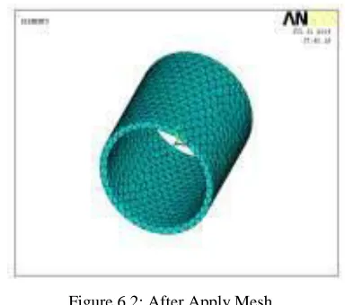
Generate Mesh
Meshing is done by using size controls command of lines, the line of specimen is divided
to get a good mesh. After that mesh area is selected as shown in Fig
[Mesh] < [Pick All] < [Close] Warning.
Figure 6.2: After Apply Mesh
Apply Loads
Loads – Define Loads – Apply – Thermal – Temperature
Temperature –558K
Loads – define Loads – Apply – Thermal – Convection – on areas
Bulk Temperature – 313K
Film Coefficient – 0.005W/mm2K
Figure 6.3: after Apply Loads
Solution
Solution – Solve – Current LS – ok
Post Processor
Available online:
https://edupediapublications.org/journals/index.php/IJR/
P a g e | 538According to the contour plot, at inner surface the maximum temperature distribution is 558and at outer surface the minimum is 313.002
General Post Processor–Plot Results – Contour Plot - Nodal Solution – Thermal Gradient Vector sum
General Post Processor –Plot Results – Contour Plot - Nodal Solution – Thermal flux vector sum
According to the contour plot, at inner surface the maximum rate of heat transfer (heat flux) area is 1.251and at outer surface the minimum is 1.092
Like this for different composition different analysis was carried out.
RESULTS
ALUMINUM ALLOY 6061
Nodal
Thermal Thermal
Tempe
Gradient Flux rature
Tap Water
Without 558 6.948 1.251 Coolant-5000
Distilled Water
Without 558 12.567 2.262 Coolant -10000
Distilled water
with coolant- 558 0.53933 0.097079 350
ALUMINUM ALLOY 7475
Nodal
Thermal Thermal Tempera
ture Gradient Flux
Tap water
without 558 8.78 1.212 coolant-5000
Distilled water
without 558 15.49 2.138 coolant-
10000 Distilled
water with 558 0.701722 0.096838 coolant-350
CONCLUSIONS
Available online:
https://edupediapublications.org/journals/index.php/IJR/
P a g e | 539transfer rate since thermal flux is more.So we can conclude that by analytically and theoretically Aluminum Alloy 6061 is better for cylinder. But cooling fluid Distilled water without coolant is better analytically and Distilled water with coolant is better theoretically.
REFERENCES
Leong, K.Y., Saidur, R., Kazi, S. N., &Mamun, A. H. (2010). Performance Investigation Of An Automotive Car Radiator Operated With Nanofluid-Based Coolants (Nanofluid As A Coolant In A Radiator). Applied Thermal Engineering, Vol 30, Issue 17/18, P2685-2692.
Heat and Mass transfer by R.K. Rajput
MohdRajuli, M. B. (2006). TeknologiAutomotif :PengenalanSistem. PetalingJaya : IBS BukuSdn Bhd.
Nice, K. (n.d.). How Car Cooling Systems Work. Retrieved 11 July 2012 from
http://auto.howstuffworks.com/cooling-system3.htm
Ofria, C. (2006). A Short Course on Cooling Systems. Retrieved 11 July 2012 from http://www.familycar.com/classroom/Cool ingSystem.htm
&Kalam, M. A. (2011). Integration of 1D and 3D Simulations of Engine Cooling System: After Keyed Off. IEEE, P46 -50. DOI 10.1109/DCABES.2011.53
Peyghambarzadeh, S. M., Hashemabadi, S. H., Hoseini, S. M., &SeifiJamnani, M. (2011). Experimental Study Of Heat Transfer Enhancement Using Water/Ethylene Glycol Based Nanofluids As A New Coolant For
Car Radiators. International
Communications In Heat & Mass Transfer, Vol. 38, Issue 9, P1283-1290.
Ross, S. (2006). An Antifreeze Antidote?
Aftermarket Business, Vol 116, No.7, Advanstar Publication.
Salah, M. H., Mitchell, T. H., Wagner, J. R., & Dawson, D. M. (2010). A Smart Multiple-Loop Automotive Cooling System— Model, Control, and Experimental Study.
IEEE/Asme Transactions On
Mechatronics, Vol. 15, No. 1, 117 – 123.