EM Fields inside a Rotating Circular Hollow Dielectric Cylinder:
Numerical Simulation in 2Ds
Mingtsu Ho*, Li-An Tsai, and Cheng-Jr Tsai
Abstract—The electromagnetic (EM) fields inside a rotating circular hollow dielectric cylinder were numerically calculated in two dimensions, and the numerical results were presented in this paper. The simulation was carried out by using the method of characteristics (MOC) for the solutions of the time-domain Maxwell equations with the application of the passing center swing back grids (PCSBG) technique in the modified O-type grid system. To illustrate the effects of the rotating hollow dielectric cylinder on the EM fields inside the cylinder, the cylinder may be set to rotate at impractically, extremely high angular frequencies. The use of PCSBG is to overcome the difficulty of the deformed grid cells resulting from the rotating object while the modified O-type grid system satisfies the requirement of minimum number of grid within the shortest wavelength of interest in the larger radius regions where the regular O-type grid fails. A Gaussian EM pulse is utilized as excitation source and set to illuminate the hollow cylinder which is made of either non-magnetic or impedance matching materials. For clear examinations the numerical results of EM fields at and around the cylinder center are exhibited. Several electric field distributions are also shown.
1. INTRODUCTION
The electromagnetic scattering problems from hollow dielectric cylinders have received researchers’ attention for the theoretical interest in both physics and engineering since the mid 1960s. Harrison studied the propagation of Gaussian EM pulses through infinite sheets into both hollow cylinders and spherical shells and gave analytical expressions in 1964 [1]. In the study, Harrison used plates, cylinders, and spheres that are made of aluminum and have no slots. Wieting et al. used a conducting cylinder with a single axial aperture as a standard test object and studied the behavior of EM fields inside through both experimental measurements and numerical computations [2]. In 1975, Datta and Som numerically studied the scattered electromagnetic fields inside a hollow lossless dielectric cylinder by illuminating it with TM waves [3]. The nonlinear nature of most physical problems calls for numerical techniques as tools for practical mathematical calculations. The presence of either multiple objects or irregular shapes of objects always increases the complexity of problems even with the fact that a variety of simplified assumptions and approximation approaches are helpful. So far, the object of interest is stationary. Once it is not at rest, the degree of complexity of problems becomes higher so does the difficulty in solving these problems both theoretically and numerically. Researchers who have made efforts for analytical solutions or mathematical expressions for such problems rarely have decent results in return. Since early 1950s, many researchers have been studying the scattered EM fields from various objects undergoing different types of motion [4–10]. The role of numerical techniques becomes more and more significant as most nonlinear and complicated problems can be mathematically modeled and numerically solved. This partially thanks to the tremendous advance of computing power in both hardware and algorithms supporting researchers to tackle difficult problems with complex structure.
Received 23 October 2015, Accepted 24 November 2015, Scheduled 4 December 2015
* Corresponding author: Mingtsu Ho ([email protected]).
Most of all, the computational results provide researchers with detailed trends for better understanding the nature of problems
The method of characteristics (MOC) was developed for the solutions of the time-domain Maxwell’s equations and reported to generate compatible results with that by finite-difference time-domain (FDTD) where an infinite long PEC strip is under the illumination of a Gaussian EM pulse [11]. MOC was later on applied to the reflecting problems from a perfect surface which is traveling and/or vibrating and produced results in good agreement with theoretical values [12, 13]. In [13], the perfect surface travels at extremely high velocity, 90% of the speed of light. Computational results generated by MOC were found to give reasonable trends in the following cases: the effects of medium conductivity on the EM fields propagating onto conducting dielectric half space [14] and the transmission of EM pulse through lossless non-uniform dielectric slab [15]. To overcome the grid distortion caused by the rotating cylinder, PCSBG was proposed based on the nature of MOC that all field components are defined at the cell center [16]. MOC in coalition with PCSBG was demonstrated to yield reasonable computational results in the scattered EM fields from rotating circular cylinder under the illumination of Gaussian EM pulse [17, 18].
2. GOVERNING EQUATIONS AND BOUNDARY CONDITIONS
In the numerical model, a circular hollow dielectric cylinder rotates with an extremely high angular velocity, located at the center of the modified O-type grid and under the illumination of a Gaussian plane EM pulse in free space. The governing equations are the time-domain Maxwell equations
∂ B
∂t +∇ ×
E = 0 (1)
∂ D
∂t − ∇ ×H = 0 (2)
whereE and D are the electric field strength and electric flux density, andH and B are the magnetic field intensity and magnetic flux density. Both axis of the hollow dielectric cylinder and the polarization of the electric field of EM pulse are along the z-axis. MOC requires that Maxwell’s equations have to be cast in the form of Euler equation and then transformed from the Cartesian system (t,x,y) to the curvilinear system (τ,ξ,η), which yields
∂Q ∂τ +
∂F ∂ξ +
∂G
∂η = 0 (3)
where q= [ Bx By Dz ]T,f = [ 0 −Ez −Hy ]T,g = [ Ez 0 Hx ]T,Q=Jq,F =Jf,G=Jg, and the symbolJ is the Jacobian of the inverse transformation and defined as
J = det∂(x, y)
∂(ξ, η)
. (4)
The definition of the central difference is given by
δk(φ) = (φ)k+1
2 −(φ)k−12 (5)
where symbolφrepresents vectorF orGin Eq. (3) corresponding respectively to theξ- orη-direction of the curvilinear coordinate system; the cell indexing k designates the grid center; the one-half indexing indicates the interface between cells. Note that MOC evaluates the flux difference across every cell interface. Applying Eq. (5) to Eq. (3), one obtains
Qn+1−Qn
Δτ +
δiF
Δξ +
δjG
Δη = 0. (6)
the spatial derivatives of F and G, respectively. Through the applications of the flux vector splitting technique and the lower-upper approximate factorization scheme, MOC solves the system of equations. There are two types of boundary conditions: On both the air-dielectric and dielectric-air interfaces, the boundary conditions assure that the tangential components of both electric and magnetic field intensities and the normal components of both electric and magnetic flux densities must be continuous. At the outermost domain boundary, the boundary conditions guarantee that the outgoing EM fields keep propagating outward.
3. THE PCSBG TECHNIQUE
The schematic diagram of the problem is illustrated in Figure 1. Generally, a regular O-grid system is suitable for the present problem. However, as depicted in Figure 2(a), in larger radius regions, grid cells become long trapezoids (an insufficient representation of circle) such that they fail to meet the requirement of grid density for EM problems, and a minimum number of grids within the shortest wavelength of interest must be satisfied. The modified O-type grid is proposed for the solution, and its simplified version is given in Figure 2(b) where each grid splits into two from segment to segment. Pointed out in the diagram are the material constants of dielectric cylinder (εr,μr) and the two passing center swing back grid (PCSBG) layers. Note that both PCSBGs are two layers of grids in air adjacent to the cylinder and will suffer from deformation when the cylinder begins to rotate.
Figure 3 demonstrates the previously mentioned condition where without the PCSBG treatment, the two layers of grids immediately next to cylinder are twisted as the hollow cylinder rotates in the
0o
90o
Figure 1. Definition of problem.
Air Air Air
PCSBGs (εr, μr)
(a) (b)
Figure 3. Deformed grids caused by the rotating cylinder.
(a) (b)
Figure 4. PCSBGs: (a) grid lines are about to pass the center point; (b) rotation restarts after the swing back.
black arrow direction. The mechanism of PCSBGs is displayed in Figures 4(a) and 4(b) in which the letter K stands for a cell in cylinder, and two arrows highlighting the skew grid lines connecting to the side of the K cell are used to assist in explaining PCSBGs. At a certain moment of time, all grid lines inside the rotating cylinder are half way passing the grid as in Figure 4(a). Then in Figure 4(b) it is the very instant when PCSBGs are to be maneuvered to swing back by one grid to the right of the K cell. As illustrated above, MOC solves the time-domain Maxwell equations with the rotating hollow cylinder in team working with PCSBG and the modified O-grid. During the process, MOC constantly and precisely updates every change in grid measurement and orientation of those dynamic grids.
4. THE PROBLEM
diagram is the free space outside the cylinder taking up another 440 mm; consequently, the measurement of the computational domain is 500 mm in radius.
For the purpose of clear observations of how the rotating hollow cylinder affects the propagation of the EM fields, during the simulation the cylinder rotates at extremely, impractically high angular frequencies. The angular frequency ω is measured on the basis of the whole Gaussian temporal span 1.92 ns meaning that it takes cylinder 1.92 ns to make one complete cycle (ω = 1) which yields equivalently any point on the outer surface of cylinder experiences an instantaneous velocity of 65.4% of the speed of light.
The grid density is uniformly 250 per meter in radial direction and ranges from 210 to 680 per meter circumferentially. The computational domain is composed of three segments: inside air, cylinder, and outside air. Each section contains three zones within which every ring of grid has the same number of cells. They are respectively inside air: 16, 32, 64, cylinder: 64, 128, 256, and outside air: 256, 512, and 1024. The total numbers of layers and grids are 144 and about 88000, respectively.
5. NUMERICAL RESULTS
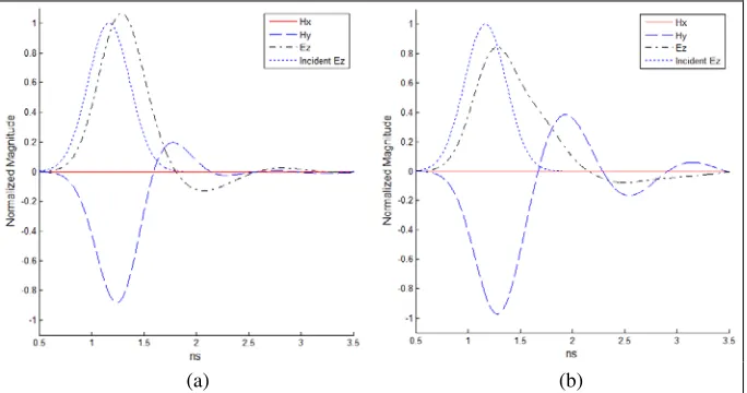
Since the EM fields initially propagate along x direction toward the cylinder, the magnetic field components along the x-axis (Hx) are expected to be zero in magnitude at the center of stationary hollow cylinders as in Figure 5 where the following are given, Hx (solid), Hy (dashed), and Ez (dash-dot) along with the incident Ez (dotted) serving as a reference recorded at the cylinder center. It is obviously noted thatHx is a flat-liner as expected and that the observed EM fields inside the dielectric cylinder oscillate more than that in the impedance matching due to the multiple transmission/reflection inside the dielectric cylinder. On the other hand, one expects to observe, because cylinder is rotating, that Hx becomes non-zero, the evidence of the effects of the rotating cylinder on the propagation of EM fields. In Figure 6 as expected Hx component is no longer zero in magnitude due to the fact that the cylinder is rotating.
(a) (b)
Figure 5. EM fields at the center of cylinder (ω= 0): (a)εr =μr= 2. (b) εr = 4,μr= 1.
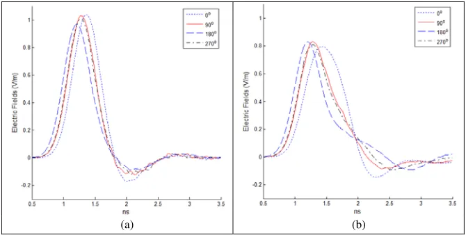
Figures 7 and 8 are theEz components recorded around center for different cylinders (εr =μr= 2 and εr= 4, μr = 1) rotating at different angular frequencies (ω = 0 andω = 0.3). When cylinders are at rest, EM fields are symmetric about thex-axis, and the twoEz sampled along they-axis coincide as in Figures 7(a) and 7(b). It is clearly observed in Figure 8 that all fourEz slightly fluctuate and that they (sampled at 90◦ and 270◦) are no longer overlapped.
(a) (b)
Figure 6. EM fields at the center of cylinder (ω= 0.1): (a) εr=μr = 2, (b)εr= 4, μr= 1.
(a) (b)
Figure 7. Ez around the cylinder center with ω = 0: (a)εr=μr = 2, (b)εr= 4, μr= 1.
(a) (b)
(a) (b)
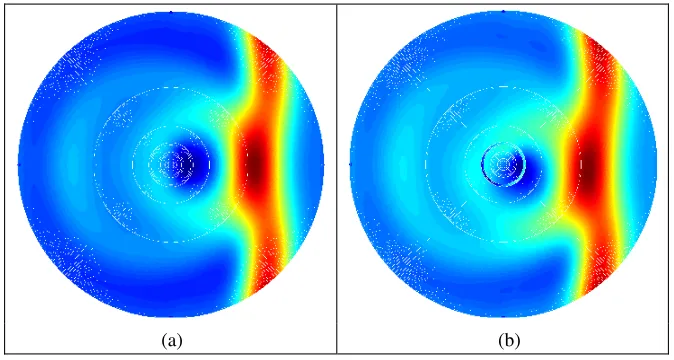
Figure 9. Electric field (Ez) distributions (εr =μr= 2): (a) ω = 0, (b)ω = 0.3.
(a) (b)
Figure 10. Electric field (Ez) distributions (εr= 4, μr = 1): (a) ω= 0, (b) ω= 0.3.
6. CONCLUSION
The computational results, produced by the method of characteristics team-working with the passing center swing back grids technique and numerically solving the time-domain Maxwell equations in modified O-type grid system for the scattering EM problems from rotating circular hollow dielectric cylinders, show reasonable trends revealing the evidence of the effects of the rotating cylinders on the propagation of the EM fields. With such an arrangement, the drawback of regular O-grid system and the difficulty of grid deformation caused by the rotating object are overcome. In this paper, all the EM field components sampled at the cylinder center, four electric field intensities around the cylinder center, and several electric field distributions over the numerical domain show reasonable trends
REFERENCES
2. Wieting, T. J., T. D. Andreadis, J. M. Kidd, W. Quade, A. I. Namenson, L. F. Libello, C. D. Schleisiger, and C. M. Butler, “Electromagnetic field investigations inside a hollow cylinder,”The International Journal for Computation and Mathematics in Electrical and Electronic Engineering, Vol. 14, No. 4, 223–227, 1995.
3. Datta, A. K. and S. C. Som, “Numerical study of scattered electromagnetic field inside a hollow dielectric cylinder. 2: Scattering of two phasematched beams,” Applied Optics, Vol. 14, No. 7, 1524-7, 1975.
4. Rice, S. O., “Reflection of electromagnetic waves from slightly rough surface,”Commn. Pure Appl. Math., Vol. 4, 351–378, 1951.
5. Beckman, P. and A. Spizzichino, The Scattering of Electromagnetic Waves from Rough Surfaces, Pergamon, New York, 1963.
6. Baeva, T., S. Gordienko, and A. Pukhov, “Theory of high-order harmonic generation in relativistic laser interaction with overdense plasma,”Physical Review E, Vol. 74, 046404, 2006.
7. Kleinman, R. E. and R. B. Mack, “Scattering by linearly vibrating objects,” IEEE Transactions on Antennas and Propagation, Vol. 27, No. 3, 344–352, May 1979.
8. Cooper, J., “Scattering of electromagnetic fields by a moving boundary: The one-dimensional case,”
IEEE Transactions on Antennas and Propagation, Vol. 28, No. 6, 791–795, November 1980. 9. Harfoush, F., A. Taflove, and G. Kriegsmann, “A numerical technique for analyzing electromagnetic
wave scattering from moving surfaces in one and two dimensions,” IEEE Trans. Antennas Propagation, Vol. 37, No. 1, 55–63, January 1989.
10. Cooper, J., “Longtime behavior and energy growth for electromagnetic waves reflected by a moving boundary,”IEEE Transactions on Antennas and Propagation, Vol. 41, No. 10, 1365–1370, October 1993.
11. Donohoe, J. P., J. H. Beggs, and M. Ho, “Comparison of finite-difference time-domain results for scattered EM fields: Yee algorithm vs. a characteristic based algorithm,”27th IEEE Southeastern
Symposium on System Theory, March 1995.
12. Ho, M., “Scattering of EM waves from traveling and/or vibrating perfect surface: Numerical simulation,” IEEE Transactions on Antennas and Propagation, Vol. 54, No. 1, 152–156, January 2006.
13. Ho, M., “EM scattering from PEC plane moving at extremely high speed: Simulation in one dimension,”Journal of Applied Science and Engineering (JASE), Vol. 17, No. 4, 429–436, December 2014.
14. Ho, M. and F.-S. Lai, “Effects of medium conductivity on electromagnetic pulse propagation onto dielectric half space: One-dimensional simulation using characteristic-based method,” Journal of Electromagnetic Waves and Applications, Vol. 21, No. 13, 1773–1785, 2007.
15. Ho, M., F.-S. Lai, S.-W. Tan, and P.-W. Chen, “Numerical simulation of propagation of EM pulse through lossless non-uniform dielectric slab using characteristic-based method,” Progress In Electromagnetics Research, Vol. 81, 197–212, January 2008.
16. Ho, M., “Numerically solving scattered electromagnetic fields from rotating objects using passing center swing back grid technique: A proposal,”Journal of Electromagnetic Waves and Applications, Vol. 23, No. 23, 389–394, January 2009.
17. Ho, M., “Simulation of scattered fields from rotating cylinder in 2D: Under illumination of TE and TM gaussian pulses,”PIERS Proceedings, 1646–1651, Moscow, Russia, August 18–21, 2009. 18. Ho, M., “Simulation of scattered EM fields from rotating cylinder using passing center swing back