Microstrip Patch Antenna: A Design to Study the Parametric
Trade-off
Shivani Chauhan1, Mamta Mittal*,2, Aakash Saini3
1,3Department of Electronics and Communication Engineering
Maharaja Surajmal Institute of Technology, GGSIPU, New Delhi, India
2Department of Computer Science and Engineering
G.B. Pant Govt. College of Engineering, GGSIPU, New Delhi, India *Email: [email protected]
Abstract- In the proposed work an experimental design of microstrip patch antenna has been developed to study the
various parameters controlling the
performance of the antenna. A microstrip patch antenna for optimum return loss, gain, directivity, efficiency and radiated power has been developed. Various design for rectangular microstrip patch antenna, 1x1, 1x2, 2x2, 1x4, 2x4 and 4x4 rectangular microstrip patch arrays with inset feed microstriptechniques
have been implemented. After the
implementations, major performance
governing parameters are plotted against frequency to analyze the characteristics of the developed rectangular microstrip patch antenna. Due to stentorian return losses and complex feeding techniques for higher order arrays, the array design has been limited to 4x4. The frequency of designed antenna has been selected as 2.4GHz. All the designs and have been simulated in Advanced System Design (ADS). Metric graphs of reflection losses, gain, directivity, efficiency and radiated power have been plotted against the frequency using the same. Though plotting of the radiation pattern lobes is possible, it has not been implemented due to its less accurate degree of measurement. Finally, all the plotted metrics have been studied, and a trade-off among the parameters has been analyzed for the optimum performance of the designed
rectangular microstrip patch antenna. This trade-off analysis can be used to implement application-specific rectangular microstrip patch antennas for optimum performance in their respective field.
Keywords- Parametric trade-off; Feed techniques; Return loss;Patch
1 Introduction
Deschamps first proposed the concept of Microstrip Antennas (or Radiation from Microstrip Planes) in 1953. The first patent for the same was issued in 1955 in France. Microstrip is probably the most successful and revolutionary antenna technology ever. Since then, extensive research and development are going on in the field of Microstrip antennas and arrays, aiming at exploiting its different merits. Microstrip Patch Antennas are advantageous as it is light weight, less volume, less surface area, cheap, feasible fabrication and but with low gain, more ohmic losses in feed structures leading to low efficiency, less bandwidth, Poor end fire radiator and so on. MSA isbeing increasingly used due to printing feasibility onto a circuit board.
1. Light Weight, smaller size and lesser volume and thin configuration and can be made conformal.
2. Easy Fabrication and can be molded in any shape according to the host surface.
3. The fabrication process is compatible with Monolithic Microwave Integrated Circuit (MMIC) and Opto-Electronics Integrated Circuits (OEIC), hence no new fabrication process required, making microstrip (MSA) antenna low in cost.
4. Supports both linear and circular polarization with simple feed.
5. Multi-Frequency Antennas is easy to design.
6. Mechanically robust when mounted on a rigid surface.
7. Easy to form large arrays with half wavelength or lesser spacing.
Research is going on worldwide to overcome these limitations. Techniques have been introduced for increasing bandwidth up to 60% array configurations have been introduced to handle higher power, etc.
Microstrip antennas have been a domain of interest for engineers and scientists in the field of wireless communication for more than four decades now. They are commonly engaged in the day to day and military applications such as radio-frequency applications, broadcasting and so on. In fact, nowadays, every cell phone is equipped with the microstrip patch antenna due to their smaller size. Microstrip Patch Antenna, in its simplest configuration, consists of a radiating patch kept above a conducting ground plane. In between is a dielectric material (known as substrate) with dielectric constant not larger than 10. In this work, we will deal with the designing of a microstrip antenna and study its different parameters Bandwidth, efficiency, gain and plot the graphs between all these parameters and then compare it with
arrays of the antenna and find out the results for the lower gain and highest efficiency. The paper further has been organized as follows. Section 2 defines the basic terms used in this article. Section 3 includes the related work done in this research fieldand the literature followed while doing this work. Section 4 describes the implemented design and process flow followed in details. Simulation results and metric calculated for the developed prototype are given under section 5. Section 6 concludes and highlights some areas of improvisation to widen the scope of the design in the future.
2 Basic Definitions
1.Patch antenna: A low profile, mountable over at surfaces, consisting of arectangular patch of metal, radio antenna for high-frequency applications is called Patch antenna.
2.Fringe field: The peripheral magnetic field outside of the electromagnetic core. Field space varies depending upon the dimensions of the design adopted.
3.Scattering parameter: It is a matrix of parameters defined for two-port linear electrical networks. S11 is the most quoted
parameter in the field of antennas. It measures the degree of reflection of power from the
antenna. Hence also known as
reflectioncoefficient.
4.Antenna Array: It is a particular geometric cluster of antennas to form a single antenna with amplified characteristics as a whole. 5.Radiation Efficiency: It is the degree of the
ability of an antenna to convert electrical power into radiation power.
6.Antenna Bandwidth: It is defined as the range of radio frequency within which a given return loss can be maintained.
to the radiation launched into that antenna, Pin, usually expressed as a negative number in dB. RL = 10log10(Pout/Pin)
.
8.Photolithography: It is the most adapted method of the fabrication of the circuit boards and integrated circuits.
9.Circular polarization: A type of polarization in an electromagnetic field, where electric field vector remains constant in length, but its direction keeps on rotating with respect to the time at a steady state, orthogonal to the propagation of the wave.
10.Loss tangent: The ratio of the lossy reaction to the electric field E in at the media interface is called loss tangent.
11.Impedance matching: A technique to maximize the transfer of the power from the source to the load by matching the source and load impedance by minimizing the reflection losses. 12.Radiation resistance: Antenna is more or less
resistance which translates the electrical power into electromagnetic power on the air in the form of radiation. The part of the antenna which offers this translation resistance is called radiation resistance.
3 Literature Survey
The microstrip patch antennas are highly applicable in the industry for their performance and vigorous design. They are implemented in various fields like medical sciences, satellites, military systems just like in the rockets, air-crafts missiles and much more. Now their use
is at theboom in the commercial fields too, given the low cost of the substrate material and the fabrication. Microstrip patch antenna has some applications.
Field became the world when Rao et al.[1] showed the electromagnetic scattering by the surfaces of arbitrary shapes. After that, Carver et al.[2] published a paper in IEEE transactions on microstrip antenna technology. Since the introduction of patch antennas, various studies have been performed on the patch antennas to improve performance characteristics. One excellent example is work done by Newman et al.[3] to study the scattering from a microstrip patch. Pozar et al.[4] introduced the first application of the field by designing millimeter wave microstrip reflectarrays. The application of patch antenna due to their properties accelerated in the various fields. Yang et al.[5] wideband E-shaped patch antennas for wireless communications.
3.1 Radiation Mechanism
Radiation mechanism of microstrip patch antennas depends predominantly upon following two factors
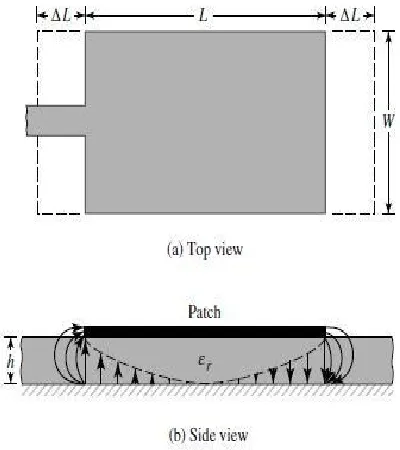
-Fringing effect and effective dielectric constant: To understand the radiation
mechanism, consider a Microstripline, and the typical electric field for the same is shown in figure 1
From the electric fields shown above, one can observe that the fringing is in both air and substrate. This is a non-homogeneous line of two dielectrics, typically the substrate and the air. From the figure, it is clear that most of the electric field lines exist in the substrate and some minor parts of it are in the air. Since practically W/h >> 1 and one the electric field lines concentrate mostly into the substrate. Due to this, fringing makes the microstrip look wider as compared to its physical dimensions and is represented by Weff.Since some of the
waves travel in substrate, and some of the waves travel in air, an effective dielectric constant is introduced to define fringing and
Fig. 2 Physical and Effective dimensions of rectangular microstrip patch antenna
propagation of the wave in the antenna. The effective dielectric constant is defined
as the area where electric fields travel has approximately equivalent
characteristics are making calculations easier.
- Effective Length: The patch of the antenna behaves electrically greater than its physical dimensions, as per the fringing effect. This largerand electrical dimension is known as the effective length of the antenna.
3.2 Feeding Techniques
Each antenna needs to be fed to the input signal or in case of receiving; the signal needs to be withdrawn from the antenna. To do so, feed point is set at the antenna where the connector is attached. There are multiple techniques available to decide the feeding point. The most commonly used feeding techniques are discussed in this section. The four most commonly used feed techniques are microstrip line feed, coaxial feed, aperture coupling and proximity coupling. All the feed techniques are used as per the requirements and power specifications. Sometimes size, gain, and bandwidth of the required antenna are also considered for the selection of feeding techniques. Inset feed technique has been implemented in the developed design for array antenna due to the complexity of other feeding techniques for higher order arrays.
3.3 Current Advancements
and Yang et al.[8] proposed a reconfigurable patch antenna using switchable slots for circular polarization diversity. A reconfigurablemicrostrip antenna for switchable polarization, proposed by Sung et al.[9] is also a good example demonstrating the potential future scope in this field. Various antennas have been implemented from the microstrip-fed rectangular antenna to 4x4 rectangular array antennas until optimum performance metrics are obtained in the simulations and results on ADS as discussed in subsequent sections.
4 Implemented Design and Process Flow
The proposed work intends to design and stimulate the rectangular microstrip patch antennas with different array arrangements gradually analyzing the performance parameters concerning frequency of the application. The design frequency has been assumed at 2.4 GHz. Various design models for single rectangular patch antenna, normal microstrip patch antenna, 1x1, 1x2, 1x4, 2x2 and 4x4 microstrip antenna with inset feed array had been implemented, and their parameters have been calculated. The microstrip inset feeding technique has been adopted for the array design due to the complexity of feeding for higher order array.
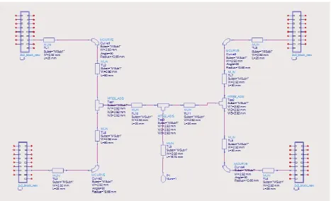
The designed schematic for a 4x4 microstrip patch antenna with inset feed array is depicted in figure 3
After continuously observing the performance parameters by simulating each design, optimum design parameters have been found for the 4x4 microstrip antenna with inset feed array. For higher order array structures, the
gainwith respect to the frequency, starts to deter.
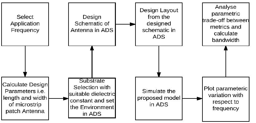
The design has been developed on the ADS [10] tool of Keysight Technologies. The following process flow as shown in figure 4 has been followed while designing of the MSA.
Fig. 4 Process flow followed for the MSA design.
First of all, an application frequency has been selected as 2.4 GHz in this case, that is the normal frequency for Wi-Fi applications. Now crucial design parameters, i.e., length and width, deciding the performance of the microstrip patch antenna have been calculated using the electromagnetic principles and formulas. Now as per application requirement and suggested by the calculations a substrate material and a dielectric material is selected for the optimum performance metrics. After selecting the substrate and dielectric material, an environment has been set up in the ADS as per the application requirement for a design ensuring optimum performance in real conditions. After environmentset-up, the schematic for the proposed model has been implemented on the ADS as shown in figure 3.
The layout design has been generated from the designed schematic by ADS. All simulations have been carried out on the layout design and ve parameters Return Loss, gain, directivity, efficiency and Radiated power are plotted against varying frequency in GHz range. A pattern has been observed in the parameters, as the gain and directivity is increased, Bandwidth is decreased. So a trade-off is set among various performance parameters giving the designers nothing but a choice to prefer a more dominant parameter in the application specific design.
5 Simulations and Results
float in the air just above the ground plane. Hence, other substrates are considered for the same. Different type of substrates is available in the market for antenna designing. These substrates are classified into types such as ceramic substrates, semiconductor substrate, ferromagneticsubstrates, synthetic substrates, composite material substrates, etc. One can
check out the list of substrates available in substrate editor.
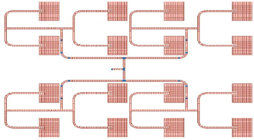
In the proposed work copper has been selected by the authors. After setting the application specific environment in the ADS, the following layout design for a 4x4 microstrip inset feed patch antenna is implemented as depicted in figure 5 below
Fig. 5 Layout of the 4x4 MSA design.
Fig. 6 Magnitude of S11vs. Frequency
As it is observed in the graph, S11 losses are minimum at the frequency of the application, i.e., 2.4GHz.
Figure 7 depicts the frequency spectrum graph of all the four major Parameters likegain, directivity, efficiency and radiated power of the designed antenna
Fig. 6 Gain, Directivity, Efficiency and Radiated power against frequency of the designed MSA
Now, here in this design, the gain has started reducing due to the extensive line and material losses along with the reduction in bandwidth and hence, the inset feed microstrip patch antenna array designis not used for higher order arrays.
6 Conclusion
The proposed work follows an ‘analyze and progress’ approach by designing the rectangular microstrip patch antennas from simple rectangular patch antenna to the fourmicrostrip inset feed line patch antenna
array to find the optimum performance metrics suggested by the calculations. At last, the optimum metrics are shown by 4x4 inset feed array microstrip antenna for the selected frequency of application, substrate material, and patch material.
Efficiency also follows a bell-shaped curve like gain giving maximum efficiency of 55 dB around 2.37 GHz frequency and lowers down at higher frequencies. Power radiated follows same bell-shaped curve like gain and efficiency but steeper than both having a maximumpower of 0.8mW att radiated at 2.45 GHz.
The developed prototype can be developed into a more larger, more efficient and more directional by making higher order arrays with complex and efficient feeding techniques to minimize reflection losses. The scope of improvisation can be widened further by implementing advanced self-adjusting, reconfigurable characteristics on the microstrip patch array.
References
1. S. Rao, D. Wilton and A. Glisson, "Electromagnetic scattering by surfaces of arbitrary shape," in IEEE Transactions on Antennas and Propagation, vol. 30, no. 3, pp. 409-418, May 1982.
2. K. Carver and J. Mink, "Microstrip antenna technology," in IEEE Transactions on Antennas and Propagation, vol. 29, no. 1, pp. 2-24, Jan 1981.
3. E. Newman and D. Forrai, "Scattering from a microstrip patch," in IEEE
Transactions on Antennas and Propagation, vol. 35, no. 3, pp. 245-251, Mar 1987.
4. D. M. Pozar, S. D. Targonski and H. D. Syrigos, "Design of millimeter wave microstripreflectarrays," in IEEE
Transactions on Antennas and Propagation, vol. 45, no. 2, pp. 287-296, Feb 1997.
5. F. Yang, Xue-Xia Zhang, XiaoningYe, and Y. Rahmat-Samii, "Wide-band E-shaped patch antennas for wireless communications," in IEEE Transactions on Antennas and Propagation, vol. 49, no. 7, pp. 1094-1100, Jul 2001
6. Jaehoon Kim and Y. Rahmat-Samii, "Implanted antennas inside a human body: simulations, designs, and characterizations," in IEEE Transactions on Microwave Theory and Techniques, vol. 52, no. 8, pp. 1934-1943, Aug. 2004.
7. Hang Wong, Ka-Leung Lau and Kwai-Man Luk, "Design of dual-polarized L-probe patch antenna arrays with high isolation," in IEEE Transactions on Antennas and Propagation, vol. 52, no. 1, pp. 45-52, Jan. 2004
8. Fan Yang and Y. Rahmat-Samii, "A reconfigurable patch antenna using switchable slots for circular polarization diversity," in IEEE Microwave and Wireless Components Letters, vol. 12, no. 3, pp. 96-98, March 2002
9. Y. J. Sung, T. U. Jang, and Y. S. Kim, "A reconfigurablemicrostrip antenna for switchable polarization," in IEEE Microwave and Wireless Components Letters, vol. 14, no. 11, pp. 534-536, Nov. 2004.
10. Advanced Design Tool, 1985, ADS by Keysight Technologies for Windows x32 and x64,
Available:http://www.keysight.com/en/pc-