CSEIT172585 | Received : 12 Sep 2017 | Accepted : 24 Sep 2017 | September-October-2017 [(2)5: 392-401]
International Journal of Scientific Research in Computer Science, Engineering and Information Technology © 2017 IJSRCSEIT | Volume 2 | Issue 5 | ISSN : 2456-3307
392
Autonomous Hybrid Generation Scheme Based on PV Array and
Wind Driven Induction Generators with Fuzzy Logic Controller
Ande Vandana1, G. Seenaiah2 1
M.TECH Student / Dept of Electrical & Electronic Engineering: MJR College of engineering &Technology Piler, Andhra Pradesh, India
2AssistantProfessor. / Dept. of Electrical & Electronics Engineering: MJR College of engineering &Technology Piler, Andhra Pradesh, India
ABSTRACT
An isolated renewable energy systems that is construct completely in light of renewable resource however in the meantime solid is fundamental for taking care of the power requests of remote spots where utility grid is not accessible and for which hybrid wind-solar system assumes a urgent part. In this paper, a streamlined control conspire has been introduced for a remain solitary crossover PV array energized wind driven induction generator considering a three phase variable load with or without unbalance. The proposed plot abuses the toughness and cost induction generator as a reasonable option for a costly permanent magnet synchronous generator (PMSG) which is constantly utilized as a part of remain solitary little wind turbines.
Keywords: Off Gird, PV, Wind, Wind Driven Induction Generator
I.
INTRODUCTION
Over 400 million individuals in India, including 47.5% of those living in India‟s provincial zones, still has no entrance to power. As a result of the remoteness of quite a bit of India‟s un-jolted populace, sustainable power source can offer a financially reasonable methods for giving associations with these gatherings. There is a solid requirement for off grid power generation, to cater those divisions, where either grid augmentation is either not achievable or not savvy. Separated sustainable power source system that is construct completely in light of natural resources and in the meantime solid is vital for taking care of the power requests of remote spots where utility grid is not accessible. For which hybrid wind-solar assume a vital part. Since sun oriented and wind have inalienable complimentary profile, it turns into an appealing decision for a hybrid sustainable power source conspire. Numerous hybrid schemes have been as of now revealed in writing and additionally exists by and by .Normally in cross breed wind-sun oriented schemes, PMSG (permanent magnet Synchronous generators), is constantly utilized as the wind driven generator particularly for an independent applications. In such hybrid schemes in light of PV and wind driven PMSG,
supply the required load even without battery. However in this work, a settled resistive load has been considered for the controller configuration and additionally unbalance in load has not been considered. Further to this, hybrid scheme in view of PV and IG revealed in the writing, require an utility grid for its operation. The vast majority of them utilize a doubly encouraged induction generator, which is at the end of the day costly. It is endeavored to build up a vigorous and dependable control conspire for self-ruling hybrid system in view of PV source and wind driven induction generator that can give consistent controlled three phase output voltage for a wide range of load with or without unbalance. In the current work, an improved controller for battery less mode operation has been produced for a PV fed Boost Converter encouraged Inverter energized wind driven IG conspire (PVEWIG) to direct the inverter DC connect without battery. In this scheme, a three phase variable resistive and additionally inductive load with or without unbalance has been considered. The proposed controller guarantees voltage regulation of DC connect and enhances the power quality parameters at purpose of normal coupling (PCC) under shifting illumination, temperature of PV array and wind speed variety in the wind generator. The proposed plot has been actualized in equipment utilizing a 2.4 kW PV cluster and a 2.25 kW Wind turbine emulator driven SCIG. This paper is sorted out as takes after. Area II depicts the power circuit topology of the PVEWIG conspire. The nitty gritty clarification of the control plot is displayed in area III. The displaying and simulation comes about are arrayed in area IV and equipment approval comes about are introduced in segment V.
POWER CIRCUIT ARRANGEMENT OF THE PV ARRAY FED INVERTER EXCITED WIND converter. The voltage over the dc-dc boost converter is associated with a battery, which is modified by a three phase inverter and the IG is coordinated to the inverter output and is lock to inverter voltage and frequency. The IG would require reactive power which it would ordinarily draw from an utility system in a grid associated conspire. In the current scheme, the
receptive power required by the induction machine is provided by the PV array fed inverter.
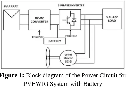
Figure 1: Block diagram of the Power Circuit for PVEWIG System with Battery
The output of the inverter goes about as a virtual grid giving a consistent voltage and recurrence. The three-phase load is associated with inverter output and is provided by PV-IG and battery or PV-IG, the load sharing being reliant on illumination and wind speed. The inverter output, IG output and load frames the purpose of normal coupling (PCC). The piece schematic of the whole PVEWIG conspire is appeared in Fig. 1. One of the exceptional elements of this half and half scheme is that, this system utilizes an induction generator without a need of either utility lattice or excitation capacitors, consequently maintaining a strategic distance from every one of the inconveniences related with it. Without battery, the real power adjust is to such an extent that the entirety of PV exhibit power and real power output of IG parallels the inverter control output which is conveyed to the load. The power adjusting is clarified in more detail in the consequent areas.
II.
CONTROL SCHEME OF THE PV ARRAY FED
INVERTER EXCITED WIND DRIVEN IG
the dc-dc boost converter utilized as a part of this scheme is appeared in Figure 2.
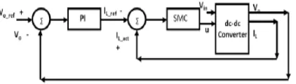
Figure 2. Block diagram of Cascaded PI-SMC controller for output voltage regulation of dc-dc boost
converter
output voltage control of dc-dc boost converter. The V-I attributes of PV cluster differs with light also, temperature and this moves the working purpose of the PV cluster. Further, the variety of wind speed changes the pole torque to the induction generator. These fluctuating parameters cause the contribution and in addition load of the dc-dc converter to change. In this occasion, the controller works in voltage regulation mode. The dc-interface voltage is directed utilizing a cascade PI-SMC control in which the external circle comprises of a PI controller and the internal circle comprises of a sliding mode current controller (SMC) as appeared in Fig. 2. The external PI controller creates a current reference from its information voltage blunder between reference (Vo_ref) and real output voltage (Vo) of dc-dc converter. The blunder between reference (IL_ref) and real Inductor current (IL_act) is given as contribution to SMC which creates the entryway pulse for the boost converter IGBT. The essential standard of SMC includes scheme of a sliding surface in its control law which would coordinate the regulation of the state factors towards a coveted source. Ordinarily in a solitary switch dc–dc converter, the control law that
state) of the converter‟s control switch and the state variable is the inductor current. In light of the general sliding mode control hypothesis, the state variable mistake is characterized as the distinction amongst real and reference esteem (of the inductor current), which shapes the sliding work given by l real l ref S i.
A. Inverter Control of PVEWIG conspire At the point when an IG is interfaced with the lattice or in the proposed conspire with a "PV fed DC-DC converter encouraged inverter", at first there is a colossal contrast between the initiated emf of the IG and the inverter voltage which causes a sudden inrush. The extent of this inrush relies on upon the underlying velocity of the
rotor and the remaining flux of the stator of the IG. On the off chance that the rotor begins from zero speed then the size of inrush is exceptionally extreme, this is typically 5 to 6 times that of the appraised current (which is the situation of an induction motor). In this hybridscheme, the IG is electrically incorporated with the inverter output when the speed of the IG is somewhat over the synchronous speed which relates to the cut in speed of the wind turbine. In this manner in such condition the extent what's more, span of the inrush is very little extreme and could be withstood by the information dc source of the inverter. In any case, the output voltage of the inverterNonetheless, the output voltage of the inverter is bit by bit expanded, by gradually expanding the tweak record of the sine PWM controller to absolutely dispense with any plausibility of inrush current.
III.
MODELING AND SIMULATION OF THE
PVEWIG SYSTEM
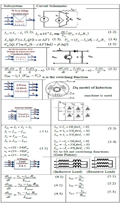
Figure 3. Block Diagram Recurrenting the Mathematical Model of PVEWIG System
Table I Mathematical Models used for recurrenting the PVEWIG system
The instantaneous current distribution at the point of common coupling (PCC) is given by (9).
The simulation piece graph of the whole hybrid plot alongside the controller executed in MATLAB/Simulink is appeared in Fig. 4. The beginning reaction of the PVEWIG system is appeared in figure 5. It could be watched the real energy of load is shared amongst inverter and IG, while the receptive energy of the load and IG is provided by the inverter. Amid beginning, the regulation file of the sine PWM inverter is step by step expanded from its underlying zero esteem, which encourages mix of IG with the inverter without any inrush current as appeared in figure 6. The unfaltering state waveforms of voltage at PCC and current of PVEWIG system counting load, IG and inverter are appeared in figure 7. The conveyance of real power among PV exhibit and IG under unsettling influences in light, wind turbine speed and load is appeared in figure 8a. For this situation the temperature is kept up consistent at 35 deg Celsius. It can be watched the system rms voltage stays steady with the exception of a brief term unsettling influence as appeared in figure 8a. Additionally the real power adjust is guaranteed among the two sources PV exhibit and IG, giving a directed yield voltage to the load. The reaction of the system for a wind speed variety at a steady load and light is appeared in figure 8b. It can be watched, the controller guarantees the power adjust what's more, keeping up consistent DC connect voltage. Further, for this situation the power conveyed by the IG increments with the wind speed while the PV control diminishes as needs be, not as much as its accessible power for the given illumination. Be that as it may, the target of the controller here is to direct the DC connect voltage in the battery less method of operation.
Figure 4. Simulation Block Diagram in MatlabRecurrenting the Mathematical Model of
HARDWARE IMPLEMENTATION AND VALIDATION
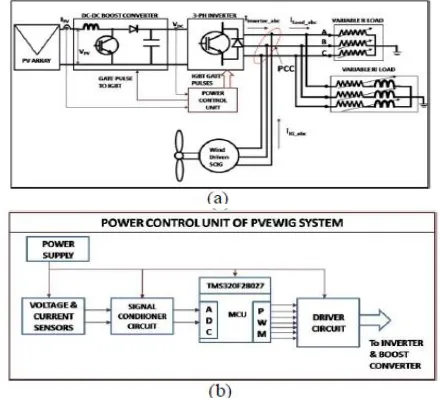
The proposed PVEWIG conspire is actualized utilizing a 2.4 kW PV cluster and a 2.25 kW Wind turbine emulator driven induction generator. The control conspire which involves a cascade PI-SMC control for the lift converter and open circle sine-PWM control for the inverter is actualized utilizing a Texas Instruments microcontroller TMS320F28027. hall Impact Voltage and current sensors are utilized to detect the inverter DC connect voltage and PV exhibit current individually. The equipment piece outline of the power circuit and the control circuit are appeared in figure 9a and 9b individually. Furthermore climate Sensors including pyranometer, temperature sensors, voltage and current sensors are utilized alongside an information data logger to screen the execution of the system for a long span. The circuit parameters including evaluations of load, PV and IG utilized for equipment execution are given in Table II, which is same as the one considered for reenactment.
Figure 9. (a) Hardware Block diagram of PVEWIG system (b) Block diagram of the Power Control Unit of
PVEWIG System
The beginning grouping of battery less PVEWIG system is clarified as takes after with reference to figure 9. Before beginning, it is required that the IG is running at a speed, more prominent than or equivalent to its synchronous speed. At first the pulse to the dc-dc boost converter alone is turned ON by the power control unit (PCU). Currently the, dc interface voltage begins getting charged till it achieves its reference esteem. The inrush current of the DC connect capacitor is constrained to the short out current of the PV cluster.
Once the DC interface voltage comes to close to its and disengaging the IG from the system in view of its speed should be possible by designing the PCU with extra speed sensors and a controllable.
load change is shown in figure 16, which demonstrates the programmed modification in load share amongst PV and IG relating to change in WTE speed and load extent. Figure 17 demonstrates the regular load sharing reaction alongside the light information caught for a brief span of 10 minutes. It can be watched the system RMS voltage stays steady regardless of the adjustments in illumination, load and WTE speed.
FUZZY CONTROLLER
Fuzzy logic is a complex numerical strategy that permits taking care of troublesome reenacted issues with many data sources and yield factors. Fuzzy logic can give brings about the type of suggestion for a particular interim of yield state, so it is basic that this scientific strategy is entirely recognized from the more commonplace logics, for example, Boolean algebra math. This paper contains an essential diagram of the standards of fuzzy logic.
Fuzzy Logic SystemToday control system are generally portrayed by scientific models that take after the laws of material science, stochastic models or models which have risen up out of numerical logic. A general trouble of such developed model is the manner by which to move from an offered issue to an appropriate scientific model. Without a doubt, today's propelled PC innovation makes it conceivable; however overseeing such system is still excessively intricate.
These unpredictable system can be streamlined by utilizing a resistance edge for a sensible measure of imprecision, dubiousness and instability amid the displaying stage. As a result, not totally idealize system comes to presence; in any case in the greater part of the cases it is fit for taking care of the issue in suitable way. Notwithstanding missing info data has officially ended up being palatable in information based system.
Fuzzy logic permits to lower many-sided quality by permitting the utilization of flawed data in sensible way. It can be actualized in equipment, programming, or a blend of both. As it were, fuzzy logic way to deal with issues' control emulates how a man would decide, just significantly quicker.
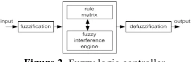
The fuzzy logic examination and control strategies appeared in Figure 1 can be portrayed as:
1. Receiving one or huge number of estimations or
other appraisal of conditions existing in some system that will be dissected or controlled.
2. Processing every got contribution as per human based, logic "assuming at that point" rules, which can be communicated in straightforward dialect words, and consolidated with conventional non- logic preparing.
3. Averaging and weighting the outcomes from all the individual tenets into one single yield choice or flag which chooses or guides a controlled system what to do. The outcome yield flag is an exact defuzzified esteem.
The following is Fuzzy Logic Control/Analysis Method diagram.
Figure 1. The fuzzy logic Control-Analysis method
To work fuzzy logic should be spoken to by numbers or portrayals. For instance, speed can be spoken to by esteem 5 m/s or by depiction "moderate". Term "moderate" can have diverse significance if utilized by various people and should be deciphered regarding the watched condition. A few esteems are anything but difficult to order, while others can be hard to decide as a result of human comprehension of various circumstances. One can state "moderate", while other can state "not quick" while depicting a similar speed. These distinctions can be recognized with help of alleged fuzzy sets.
Typically fuzzy logic control system is made from four noteworthy components displayed on Figure 2: fuzzification interface, fuzzy induction motor, fuzzy govern network and defuzzification interface. Each part alongside essential fuzzy logic operations will be portrayed in more detail underneath.
Advantages of Fuzzy Controller over PI Controller
Execution of conventional control "PI", its reaction is not all that great for non-straight system. The change is momentous when controls with Fuzzy logic are utilized, acquiring a superior dynamic reaction from the system. Or, on the other hand
The PI controller requires exact straight numerical models, which are hard to acquire and may not giveagreeable execution under parameter varieties, stack unsettling influences, and so on. As of late, Fuzzy .
Logic Controllers (FLCs) have been presented in different applications and have been utilized as a part of the power gadgets field. The upsides of fuzzy logic controllers over customary PI controllers are that they needn't bother with an exact numerical model, Can work with loose information sources and Can deal with non-linearities and are more strong than ordinary PI controllers
Proposed:
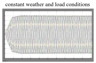
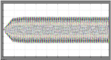
Fig 5. DC link, PV and Load RMS voltages under constant weather and load conditions
Fig 5. Inverter, Load and IG RMS currents under constant weather and load conditions
Fig 5. Load, IG and Inverter Real powers under constant weather and load conditions
Fig 5. Inverter, IG and Load reactive powers under constant weather and load conditions
Fig 6. Starting Load current under constant weather and load conditions
Fig 6. Starting Inverter current under constant weather and load conditions
Fig 6. PCC RMS Line Voltage under constant weather and load conditions
Fig 7. Steady State Voltage Inverter Voltages under constant weather and load conditions
Fig 8a. DC link, PV and Load RMS voltages under change in Irradiation and wind turbine
Speed with a constant load
Fig 8a. Load, PV and Inverter RMS currents under change in Irradiation and wind turbine Speed with a
constant load
Fig 8a. Load, IG and Inverter Real powers under change in Irradiation and wind turbine Speed with a
constant load
Fig 8a. IG speed under change in Irradiation and wind turbine Speed with a constant load
Fig 8b. Dc Link, PV and Load RMS Voltages with change in wind speed and constant load and constant
irradiation (Q=0.6 kW/Sq.mtr)
Fig 8 b. IG and Inverter Real powers with change in wind speed and constant load and constant irradiation
(Q=0.6 kW/Sq.mtr)
Fig 8 b. Wind Speed with change in wind speed and constant load and constant irradiation (Q=0.6
kW/Sq.mtr)
Proposed method THD in %
Extension method THD in %
Fig 5.6.7, 2.01% I l Fig5.6.7 , 1.84% load I L Fig5.6.7, 4.62% In Fig 5.6.7 , 2.82% i n Fig5.6.7 , 1.34% Ig Fig 5.6.7, 1.47% Ig Fig 8a , 1.93% Ig Fig 8a , 1.89% Ig Fig 8a , 1.99% il Fig 8a, 1.89% IL
Fig 8 a, 4.64% In Fig 8a, 2.55% in Fig 8 a, 1.94% Ig Fig 8a , 1.89% Ig Fig 8 b, 2.08% Il Fig 8b, 2.42% Il
IV.
CONCLUSION
A cascade PI-SMC control has been effectively executed for a dc-dc boost converter interfaced between PV cluster and a three phase voltage source inverter of a PVEWIG system for managing the inverter DC connect voltage. The demonstrating and reenactment aftereffects of the battery less operation of PVEWIG plot have been introduced. The battery less mode operation of PVEWIG system has been effectively executed and tried in equipment utilizing a 2.4 kW PV board and 2.25 kW IG driven by WTE. A thorough equipment comes about have been displayed which approves the proposed control scheme and its simulation comes about. Additionally the PVEWIG system was put into operation in ordinary working conditions for an entire day from morning to night and all the climate and electrical parameters were checked and recorded. The total field test consequences of the PVEWIG without battery is displayed, which shows the roughness and the dependability of the system. The equipment comes about substantiates that the proposed control plot is equipped for giving a controlled yield voltage to the load under a wide range of unsettling influences incorporating variety in illumination, temperature, wind speed, load and also unbalance in load, for a battery less method of PVEWIG system. The outcomes additionally imply that the PVEWIG system with the proposed control conspire is an appealing answer for disengaged off-grid applications where utility grid is not accessible.
V.
REFERENCES[1]. O. Honorati, G. L. Bianco, F. Mezzetti, and L. Solero, "Power electronic interface for combined wind/PV isolated generating system," in Proc. European UnionWind Energy Conf., Goteborg, Sweden, 1996, pp. 321-324.
[2]. B. S. Borowy and Z. M. Salameh. (1997, Mar.).Dynamic response of a stand-alone wind energy conversion system with battery energy storage to a wind gust. IEEE Trans. Energy Conversion.On line]. 12(1), pp. 73-78. Available: DOI: 10.1109/60.577283.
[4]. K. Kurosumi et al., "A hybrid system composed of a wind power and a photovoltaic system at NTT kume-jima radio relay station," in Proc.20th Int. Telecommun. Energy Conf., 1998, pp. 785-789.
[5]. N.A Orlando,M. Liserre, R.A.A. Mastromauro.A. (2013,July). Survey of Control Issues in PMSG-Based Small Wind-Turbine Systems. IEEE Transactions on Industrial Informatics.On line]. 9(3), pp. 211 - 1221. Available: DOI: 10.1109/TII.2013.2272888.
[6]. H.Shariatpanah, R. Fadaeinedjad, M. Rashidinejad. (2013,Sept.). A New Model for PMSG-Based Wind Turbine with Yaw Control. IEEE Transactions on Energy Conversion. On line].8(4), pp 929-937. Available: DOI: 10.1109/TEC.2013.2281814
Author’s Profile:
SUNIL KUMAR REDDY received
Head of the Master Degree in the department of Electrical & Electronic Engineering: MJR College of engineering &Technology Piler A.P. India.
G.SEENAIAH received
ASSISTANT PROFESSOR.
Master Degree in the department of Electrical & Electronic Engineering: MJR College of engineering &Technology Piler A.P. India
ANDE.VANDANA received