CSEIT183576 | Received : 15 May 2018 | Accepted : 28 May 2018 | May-June-2018 [ (3)5 : 464-468 ]
© 2018 IJSRCSEIT | Volume 3 | Issue 5 | ISSN : 2456-3307
Accident Detection System Using Sensors
Nagaraj Telkar*1, Pavankumar Naik*1, Pooja Ganige2, Sangeeta Hosalli2, Suma C C2, Swapna Raddi2
1Assistant Professor Department of Computer Science and Engineering, SKSVMACET, Laxmeshwar, Karnataka, India
2Student Department of Computer Science and Engineering, SKSVMACET, Laxmeshwar, Karnataka, India
ABSTRACT
The rapid growth of technology and infrastructure has made our lives easier. The advent of technology has also increased the traffic hazards and the road accident takes place frequently, which causes huge loss of life and property because of the poor emergency facilities. Our project will provide an optimum solution to this drawback by using GSM, GPS and Accelerometer. In addition to, it also takes the precaution to prevent the accident by using alcohol sensor and Temperature sensor used to detect fire. The system will send the accident location acquired from GPS along with the time. This will help to reach the rescue service in time and save the valuable human life.
Keywords: GSM-GPS System, Accelerometer, Alcohol Sensor, Temperature Sensor, Piezoelectric Sensor.
I.
INTRODUCTION
Nowadays accidents occur in all the places but major accidents occur in school zone and college zone because of high speeding of vehicles. The main objective of the system is to provide security for the vehicle user and also detects the accident if occurred and informs the respective authority through wireless technologies. If any accident occurs in highway or any other place, the accident information system will activated and message will transmitted to respective authority.
Statistical report says that the accident occur due to the following reasons; drunk driver not using the seat belt properly. This automatic accident detection system will overcome the above-mentioned problems in an effective way. According to this system, whenever a person sits in driver seat of the vehicle, the system checks for the following Parameters with the driver. The Alcohol sensor, which checks a person, has consumed alcohol or not. In case of any
accident, the vibration in vibration sensor increases beyond the limit and information sent to GSM module. The GSM can send message to respective authority thus, this system ensures the life security.
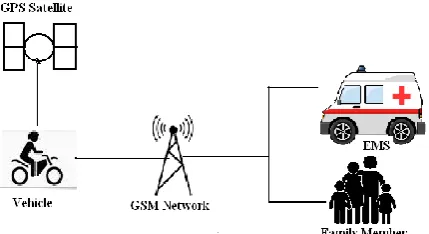
Figure 1. System Overview
within a few seconds covering geographical coordinates, the time and angle in which a vehicle accident had occurred. This alert message sent to the rescue team in a short time, which will help in saving the valuable lives. Above figure 1 shows when the accident occurs, the alert message sent automatically to the EMS (Emergency Medical Services) and to the family members. The message sent through the GSM module and the location of the accident detected with the help of the GPS module. The accident detected precisely with the help of accelerometer and ultrasonic sensor. The angle of the rollover of the car can known by accelerometer.
II.
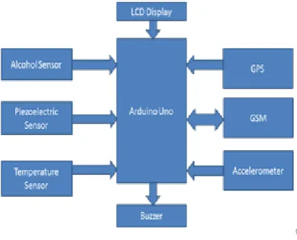
METHODS AND MATERIALThe Figure 2 shows the working of the system. It creates a smart accident detection system, detects the occurrence of an accident and sends a message to the traffic control authorities or emergency help centres in case of an accident so that immediate help can provided. It also enables real-time tracking of vehicle’s location via SMS. The system has a switch to enable driver to stop alert system in case of false alarms. This system acts as a black box to vehicles. The vehicle’s location can be viewed using Google maps, which are much easier than location in terms of latitude and longitude.
The system has five modules. The first module is Arduino Uno, the combination of GSM and GPS module in which the GPS receiver retrieves the location information from the satellite in the form of latitude and longitude real-time readings and the GSM sends the location and other information in the form of SMS. The second module is accelerometer which gives the axial information regarding the vehicle position with respect to X, Y and Z axis.
Figure 2. Working of System
The third module is piezoelectric vibration sensor which helps us to indicate in how much pressure the crash on the vehicle have occurred. The fourth module is alcohol sensor which helps us to indicate wither the driver is drunken or not. The fifth module is temperature sensor which helps us to indicate wither the car have caught the fire or not. So this is the overall review of each important modules used in this project and combindly they are used to achieve the goal of project.
A. BLOCK DIAGRAM
The block diagram of Accident Alarm System using GSM, GPS and Accelerometer is shown in the figure 3. It consists of GSM-GPS system, Accelerometer, Alcohol Sensor, Temperature Sensor and Piezoelectric Sensor. The GSM board has a valid SIM card with sufficient recharge amount to send SMS.
1. Arduino
Arduino is an open-source prototyping platform based on easy-to-use hardware and software. Arduino boards are able to read inputs-light on a sensor, a finger on a button and turn it into an output activating a motor, turning on an LED. The Arduino takes control and starts collecting the coordinates received from the GPS, which will be send to central emergency monitoring station by using the GSM module. The Arduino Software runs on Windows, Macintosh OSX and Linux operating system. Most microcontroller systems are limited to windows.
2. Alcohol Sensor
Alcohol sensor typically used as a part of the breathalyzers or breath tester for the detection of ethanol in the human breath. MQ-3 gas sensor has high sensitivity to alcohol and has good resistance to disturb of gasoline, smoke and vapour. Sensitive circuit temperature sensor, whose output voltage is linearly proportional to the Celsius (Centigrade) temperature. The LM35 does not require any external calibration or trimming to provide typical accuracies of ±1/4 °C at room temperature and ± ¾ °C over a full -55 to +150 °C temperature range. Low cost is assured by trimming and calibration at the wafer level. The LM35’s low output impedance, linear output and precise inherent calibration make interfacing to read out or control circuitry especially easy. It can be used with single power supplies are with plus and minus supplies. As it draws 60 μA from its supply, it has very low self heating, less than 0.1 °C in still air.
4. Piezoelectric sensor
A piezoelectric sensor is a device that uses the piezoelectric effect, to measure changes in pressure, acceleration, strain or force by converting them to an electrical charge. Piezoelectric sensors have proven to be versatile tools for the measurement of various processes.
5. Accelerometer
Accelerometers can be used to measure vehicle acceleration. They allow for evaluation of overall vehicle performance and response. This information can then be used to make adjustments to various vehicle subsystems as needed.
6. GPS
which contains the radio transceivers and handles the protocols for communication with mobiles. It also consists of the Base Station Controller, which controls the Base Transceiver station and acts as interface between the mobile station and mobile switching centre.
Network Subsystem: It provides the basic network connection to the mobile stations. The basic part of the Network Subsystem is the Mobile Service Switching Centre, which provides access to different networks like ISDN, PSTN etc. It also consists of the Home Location Register and the Visitor Location Register, which provides the call routing, and roaming capabilities of GSM. It also contains the Equipment Identity Register, which maintains an account of all the mobile equipments wherein its own IMEI number identifies each mobile. IMEI stands for International Mobile Equipment Identity.
8. 16*2 LCD
A 16*2 LCD means it can display 16 characters per line and there are 2 such lines. In this LCD each character is displayed in 5*7 pixel matrix. This LCD has two registers namely, command and data. The command register stores the command instructions given to the LCD. The data register stores the data and displayed on the LCD.
9. Buzzer
A buzzer or beeper is a signalling device; it gives an audible warning when an accident occurs. If it is a false alarm or if the driver feels that he does not need immediate help, there is a switch in the system that he can use to stop the working of the system.
B. FLOWCHART OF SYSTEM
The flowchart gives us the basic idea about how our system works. First of the initialization of the system is carried out in which it checks if the system is working properly or not. If the system is not working properly then it will check the 4 different conditions and tries to identity which problem is occurring.
Then it tracks position of vehicle through GPS and send SMS through GSM module.
Figure 4. Flowchart of the System
III.
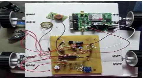
RESULTS AND DISCUSSIONFigure 5 shows the Prototypic Model of the Vehicle. Whenever any accident occurs mean piezoelectric detects the vibration and sends the information to the microcontroller , by using GPS, we will get particular location where the accident occurs, then GSM sends message to authorized members & EMS. It indicates if fire has been caught in the vehicle and also indicates if the vehicle have became upside down. It indicates it in similar way by sending SMS. It also indicates if the driver is drunk.
Figure 5. Prototypic Model of the Vehicle
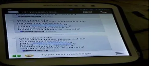
Figure 6. Message Sent on Mobile
IV.
CONCLUSION
To minimize the deaths and severe conditions due to accidents the GPS and GSM technologies are used where immediate action would be taken by the ambulance and police service which might reduces the severity. On the whole this system proves to be very cost effective and efficient. The experimentations and results prove that the system is easily implementable in real time. In future, the system can be interfaced with the airbag system of vehicle to prevent occupants from striking to the interior parts of the vehicle such as steering or window. A camera can be interfaced to the controller module that takes the photograph of the accident spot that makes a help for the tracking of the vehicle.
V.
REFERENCES
[1]. Kiran Sawant, Imran Bhole, Prashant Kokane, Piraji Doiphode, Prof. Yogesh Thorat, "Accident Alert and Vehicle Tracking System", International Journal of Innovative Research in Computer and Communication Engineering, Vol. 4, Issue 5, May 2016.
[2]. www.ieeeexplorer.com
[3]. Mrs Manasi Patil, Aanchal Rawat, Prateek Singh, Srishtie Dixit, "Accident Detection and Ambulance Control using Intelligent Traffic Control System", International Journal of Engineering Trends and Technology (IJETT) ,Volume 34-Number 8,April 2016.
[4]. Rajesh, K.M.H., N.N. Ramesh and S.M. Prakhya, Wireless Vehicular Accident
Detection and Reporting System. International Conference on Mechanical and Electrical Technology, pp: 636-640.