Predictive voltage control of Renewable Energy
Sources Fed DVR
Durga Boddu
M-tech Student Scholar
Department of Electrical & Electronics Engineering, Teegala Krishna Reddy Engineering College, Medbowli,Meerpet;
Saroor nagar,Hyderabad(Dt),Telangana, India. Email:[email protected]
A. Nagasridhar
Assistant Professor
Department of Electrical & Electronics Engineering, Teegala Krishna ReddyEngineeringCollege ,Medbowli ,Meerpet Saroornagar;Hyderabad(Dt); Telangana, India.
Email:[email protected]
Abstract- The dynamic voltage restorer (DVR) is a custom power device used for voltage compensation of sensitive loads against voltage disturbances in power distribution lines. The DVR can regulate the load voltage from the problems such as sag, swell, and harmonics in the supply voltages. Hence, it can protect the critical consumer loads from tripping and consequent losses. In this project a predictive voltage control scheme for the effective control of a transformer less dynamic voltage restorer (TDVR) is presented. This control scheme utilizes the discrete model of a voltage source inverter and an interfacing filter for the generation of the switching strategy of inverter switches. Predictive voltage control algorithm-based TDVR tracks the reference voltage effectively and maintains load voltages sinusoidal during various voltage disturbances as well as load conditions. Moreover, this scheme does not require any linear controller or modulation technique. The simulation results are presented .The proposed concept is implemented to Renewable Energy sources fed DVR using matlab/simulink software.
Index Terms—Predictive voltage control, transformer less dynamic voltage restorer (DVR) (TDVR), voltage distur- bance.
I. INTRODUCTION
Power electronic converters, ever more widely used in industrial, commercial, and domestic applications, suffer from the problem of drawing non-sinusoidal current and reactive power from the source. This behavior causes voltage distortion that affects other loads connected at the same point of common coupling (PCC).Electric Power quality is a term which has captured increasing attention in power engineering in the recent years, the measure of power quality depends upon the needs of the equipment that is being supplied. What is good power quality for an electric motor may not be good enough for a personal computer. Usually the term power quality refers to maintaining a sinusoidal waveform of bus voltages at rated voltage and frequency. The waveform of electric power at generation stage is purely sinusoidal and free from any distortion. Many of the Power conversion and consumption equipment are also designed to function under pure sinusoidal voltage waveforms. However, there are many devices that distort the waveform. These distortions may propagate all over the electrical network. In recent years, there has been an increased use of non-linear loads which has resulted in an increased fraction of
non-sinusoidal currents and voltages in Electric Network. Classification of power quality areas may be made according to the source of the problem such as converters, magnetic circuit non linearity, arc furnace or by the wave shape of the signal such as harmonics, flicker or by the frequency spectrum (radio frequency interference). The wave shape phenomena associated with power quality may be characterized into synchronous and non-synchronous phenomena. Synchronous phenomena refer to those in synchronism with A.C waveform at power frequency. Recently Active Power Line Conditioners (APLC) or Active Power Filters (APF) overcome these problems and are designed for compensating the harmonics and suppressing the reactive power simultaneously. Since basic principles of active filter compensation were proposed by Gyugyi and Strycula in 1976. In 1984, Hirofumi Akagi introduced a new concept of instantaneous reactive power (p-q theory) compensators. The generalized instantaneous reactive power theory which is valid for sinusoidal or non-sinusoidal and balanced or unbalanced three-phase power systems with or without zero sequence currents was later proposed. The active filter can be connected in series or in parallel with the supply network. The series active power filter is suitable for voltage harmonic compensation. Most of the industrial applications need current harmonic compensation, so the shunt active filter is popular than series active filter. Currently, remarkable progress in the capacity and switching speed of power semiconductor devices such as insulated-gate bipolar transistors (IGBTs) has spurred interest in APF.
the DG systems can now be actively controlled to enhance the system operation with improved PQ at PCC. However, the extensive use of power electronics based equipment andnon-linear loads at PCC generates harmonic currents, which may deteriorate the quality of power. Grid-connected three-phase photovoltaic (PV) systems are nowadays recognized for their contribution to clean power generation. A primary goal of these systems is to increase the energy injected to the grid by keeping track of the maximum power point (MPP) of the panel, by reducing the switching frequency, and by providing high reliability. In addition, the cost of the power converter is also becoming a decisive factor, as the price of the PV panels is being decreased. This has given rise to a big diversity of innovative converter configurations for interfacing the PV modules with the grid. Generally, current controlled voltage source inverters aroused to interface the intermittent RES in distributed system. Recently, a few control strategies for grid connected inverters incorporating PQ solution have been proposed. In an inverter operates as active inductor at a certain frequency to absorb the harmonic current. Butthe exact calculation of network inductance in real-time is difficult and may deteriorate the control performance. A similar approach in which a shunt active filter acts as active conductance to damp out the harmonics in distribution network is proposed in a control strategy for renewable interfacing inverter based on – theory is proposed. In this strategy both load and inverter current sensing is required to compensate the load current harmonics. The non-linear load current harmonics may result in voltage harmonics and can create a serious PQ problem in the power system network. Active power filters (APF) are extensively used to compensate the load current harmonics and load unbalance at distribution level.
2. Solutions to Voltage Quality Problems
There are two approaches to tackle power-quality problems. (a) Actions taken from the customer side or (b) Actions taken from the utility side. The first approach is called “load conditioning”, which ensures that the equipment is less sensitive to power disturbances, allowing the operation even under significant voltage distortion. The second approach consists of line - conditioning systems that suppress or counteracts the power system disturbances. Currently, line -conditioning systems are based on pulse width modulation (PWM) converters connected to low-voltage and medium-voltage distribution system in shunt mode or in series. However, with the restructuring of the power sector and with shifting trend towards distributed and dispersed generation,
the line-conditioning systems or utility side solutions will play a major role in improving the inherent supply quality [18], [19].Though there are many different methods to mitigate voltage sags and swells, the use of a custom Power device is considered to be the most efficient method. The term custom power refers to the use of power electronics controllers in a distribution system, especially, to deal with various power-quality problems [2].There are many types of Custom Power devices. Some of these devices include: Active Power Filters (APF), Battery Energy Storage Systems (BESS), Distribution STATic
synchronous Compensators (DSTATCOM),
Distribution Series Capacitors (DSC), Dynamic Voltage Restorer (DVR), Surge Arresters (SA),
Super-conducting Magnetic Energy Systems
(SMES), Static Electronic Tap Changers (SETC), Solid-State Transfer Switches (SSTS), Solid State
Fault Current Limiter (SSFCL), Static
VarCompensator (SVC), Thyristor Switched
Capacitors (TSC), and Uninterruptible Power Supplies (UPS) [7,15,20]. In this paper, an overview
of the DVR, its functions, configurations,
components, operating modes, voltage injection methods and closed -loop control of the DVR output voltage are reviewed along with the device capabilities and limitations.
3. Dynamic Voltage Restorer (DVR) System
Among the power quality problems (sags, swells, harmonics…) voltage sags are probably the most severe disturbances [7]. In order to overcome these problems the concept of custom power device has become introduced recently. One of those devices is the Dynamic Voltage Restorer (DVR), which is one of the most efficient and modern custom power device used in power distribution networks [7, 31]. A DVR is a series-connected solid-state device that injects voltage into the system in order to regulate the load side voltage. It is normally installed in a distribution system between the supply and a critical load feeder a t the so-called point of common coupling (PCC).Its primary function is to rapidly boost up the load -side voltage in the event of a voltage sag in order to avoid any power disruption to that load. There are various circuit topologies and control schemes that can be used to implement a DVR [9, 12, 22].Together with voltage sags and
swells compensation, DVR can also have
otherfeatures like: line voltage harmonics
electrical power system.
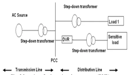
Fig. 3 Location of a dynamic voltage restorer (DVR).
The DVR is a power-electronic-converter-based device capable of protecting sensitive loads from most supply-side disturbances. As shown in Figure 4 the general configuration of the DVR consists of [7, 21, 23, 24, 25]:
3.1. Injection / Booster transformer
The Injection / Booster transformer has two purposes [8, 15, 32]: It connects the DVR to the distribution network via the HV-winding and transforms and couples the injected compensating voltages generated by the voltage source converter (VSC) in series with the incoming supply voltage. In addition, the Injection / Booster transformer serves the purpose of isolating the load from the system (VSC and control mechanism). In [8] a transformer-less DVR based on the multilevel inverter is presented. As a result of employing this inverter, the proposed DVR has lower number of switches in comparison with other multilevel DVR topologies. In [22] transformer-less and Neutral Point Connected DVRs use inductors instead of transformers to inject voltage in the system and are presented as the cheapest solutions. In [33] the proposed transformer-less DVR can satisfactorily mitigate the voltage-sag problems. The design is promising as it points at a less costly restorer of a more compact structure. It also possesses a superior voltage regulation property and has lower losses.
3.2. Harmonic filter
The main task of the harmonic filter is to keep the harmonic voltage content generated by the voltage source converters (VSC) below the permissible level. (i.e. eliminate high-frequency switching harmonics) [23].
3.3. Energy-Storage Unit
It is responsible for the energy storage in DC form. Flywheels, batteries, superconducting magnetic energy storage (SMES) and super capacitors can be used as energy storage devices. It will supply the real-power requirements of the system when DVR is used for compensation [24], [26].
3.4. Voltage Source Converter (VSC)
A voltage-source converter is a power electronic system consisting of switching devices like: Metal Oxide Semiconductor Field Effect Transistor
(MOSFET), Gate Turn-Off-Thyristors (GTO),
Insulated Gate Bipolar Transistors (IGBT), and Integrated Gate Commutated Thyristors (IGCT), which can generate a sinusoidal voltage at any required frequency, magnitude, and phase angle [23].The output voltage does not need to be of a single frequency. Voltage source converters are widely used in Variable -speed drives (VSD), but can also be used to mitigate voltage dips. The VSC is used to either completely replace the supply voltage or to inject the „missing voltage‟. The „missing voltage‟ is the difference between the nominal voltage and the actual one. Normally the VSC is not only used for voltage dip mitigation, but also for other power quality issues, e.g. flicker and harmonics [27, 28].
II. MODELING OF TDVR COMPENSATED SYSTEM
A. Description of System
The power circuit diagram of the single-phase TDVR compensated system used in this work is shown in Fig. 1 [7],
[8]. The source voltage is represented by vs. The resistance and inductance of the source are R s and Ls, respectively. The source, load, filter, and series capacitor currents are represented by is, il, if , and ise, respectively. The source is supplying to an unbalanced nonlinear load. The TDVR consists of a halfbridge VSI, an output filter (Lf and Cse), and neutral-pointclamped dc capacitors. The voltage across the filter capacitor (vse) connected in series with the line is controlled to maintain the desired voltage at the load point. The equivalent circuit of the TDVR at any time of operation is shown in Fig. 2. The term u is the switching variable. The upper and lower switches, Su and Sl, respectively, are operated in a complementary way, i.e., if the upper switch is ON (u = 1) then the lower switch will be OFF (u = −1) at any time instant and vice versa. A voltage of Vdc is maintained across each of the
A voltage of vse is generated across the series capacitor by the proper operation of the VSI to maintain the load voltage sinusoidal with constant magnitude.
B. Discrete-Time Model for Predictive Voltage Control
The equivalent circuit of TDVR shown in Fig. 2 is a second order circuit. In this circuit, the current through the filter
inductor and the voltage across the series capacitor are taken as the state variables. The dynamics of this system are given by the following differential equations:
(1)
(2) Considering if and vse as state variables and vinv and is as input variables, the state-space continuous-time equation is given as
(3) where x = [ifvse]t and z = [vinv is]t. Also, in (3)
The discrete-time state-space form of (3) at the (k + 1)th sampling instant with a sampling time of Td is given as follows:
(4) where G and H are computed as
(5)
(6) Finally, the dynamics of the considered system in the discrete-time state-space domain are given as
(7)
(8) C. Selection of Cost Function and Minimization The predictive voltage control scheme aims to operate VSI such that the load voltage is maintained constant and sinusoidal at all operating conditions. Therefore, the error between the reference injected voltage by the series capacitor and actual injected voltage should be minimized. In the literature, different cost functions based on the control criterion such as active and reactive power control, minimization of switching frequency, dc-link voltage balancing, etc., have been used [14]. In this paper, a cost function of the square of the voltage error between the predicted and the actual series capacitor is considered. It is given as follows:
(9) Replacing the predicted voltage of the series capacitor from (8) into (9)
(11)
III Renewable Energy Sources of Wind Energy Basics
Basic information on wind energy and wind power technology, resources, and issues of concern. Wind Energy and Wind Power: Wind is a form of solar energy. Winds are caused by the uneven heating of the atmosphere by the sun, the irregularities of the earth's surface, and rotation of the earth. Wind flow patterns are modified by the earth's terrain, bodies of water, and vegetative cover. This wind flow, or motion energy, when "harvested" by
modern wind turbines, can be used to
generate electricity.
How Wind Power Is Generated: The terms "wind energy" or "wind power" describe the process by which the wind is used to generate mechanical power or electricity. Wind turbines convert the kinetic energy in the wind into mechanical power. This mechanical power can be used for specific tasks (such as grinding grain or pumping water) or a generator can convert this mechanical power into electricity to power homes, businesses, schools, and the like.
Wind Turbines: Wind turbines, like aircraft propeller blades, turn in the moving air and power an electric generator that supplies an electric current. Simply stated, a wind turbine is the opposite of a fan. Instead of using electricity to make wind, like a fan, wind turbines use wind to make electricity. The wind turns the blades, which spin a shaft, which connects to a generator and makes electricity.
Wind Turbine Types: Modern wind turbines fall into two basic groups; the horizontal-axis variety, like the traditional farm windmills used for pumping water, and the vertical-axis design, like the eggbeater-style Dairies model, named after its French inventor. Most large modern wind turbines are horizontal-axis turbines.
Turbine Components Horizontal turbine components include:
blade or rotor, which converts the energy in the wind to rotational shaft energy;
a drive train, usually including a gearbox and a generator;
a tower that supports the rotor and drive train; and
Other equipment, including controls,
electrical cables, ground support equipment, and interconnection equipment.
Fig 3 Wind turbine diagram
Turbine Configurations: Wind turbines are often grouped together into a single wind power plant, also known as a wind farm, and generate bulk electrical power. Electricity from these turbines is fed into a utility grid and distributed to customers, just as with conventional power plants.
Wind Turbine Size and Power Ratings: Wind turbines are available in a variety of sizes, and therefore power ratings. The largest machine has blades that span more than the length of a football field, stands 20 building stories high, and produces enough electricity to power 1,400 homes. A small home-sized wind machine has rotors between 8 and 25 feet in diameter and stands upwards of 30 feet and can supply the power needs of an all-electric home or small business. Utility-scale turbines range in size from 50 to 750 kilowatts. Single small turbines,
below 50 kilowatts, are used for homes,
telecommunications dishes, or water pumping.
Wind Energy Resources in the United States:
Wind energy is very abundant in many parts of the United States. Wind resources are characterized by wind-power density classes, ranging from class 1 (the lowest) to class 7 (the highest). Good wind resources (e.g., class 3 and above, which have an average annual wind speed of at least 13 miles per hour) are found in many locations. Wind speed is a critical feature of wind resources, because the energy in wind is proportional to the cube of the wind speed. In other words, a stronger wind means a lot more power.
Advantages and Disadvantages of Wind-Generated Electricity
A Renewable Non-Polluting Resource: Wind energy is a free, renewable resource, so no matter how much is used today, there will still be the same supply in the future. Wind energy is also a source
of clean, non-polluting, electricity. Unlike
pollutants or greenhouse gases. According to the U.S. Department of Energy, in 1990, California's wind power plants offset the emission of more than 2.5 billion pounds of carbon dioxide, and 15 million pounds of other pollutants that would have otherwise been produced. It would take a forest of 90 million to 175 million trees to provide the same air quality. Cost Issues: Even though the cost of wind power has decreased dramatically in the past 10 years, the technology requires a higher initial investment than fossil-fueled generators. Roughly 80% of the cost is the machinery, with the balance being site preparation and installation. If wind generating systems are compared with fossil-fueled systems on a "life-cycle" cost basis (counting fuel and operating expenses for the life of the generator), however, wind costs are much more competitive with other generating technologies because there is no fuel to purchase and minimal operating expenses.
Environmental Concerns: Although wind power plants have relatively little impact on the environment compared to fossil fuel power plants, there is some concern over the noise produced by the rotor blades, aesthetic (visual) impacts, and birds and bats having been killed (avian/bat mortality) by flying into the rotors. Most of these problems have
been resolved or greatly reduced through
technological development or by properly sitting wind plants.
Supply and Transport Issues: The major challenge to using wind as a source of power is that it is intermittent and does not always blow when electricity is needed. Wind cannot be stored (although wind-generated electricity can be stored, if batteries are used), and not all winds can be harnessed to meet the timing of electricity demands. Further, good wind sites are often located in remote locations far from areas of electric power demand (such as cities). Finally, wind resource development may compete with other uses for the land, and those alternative uses may be more highly valued than electricity generation. However, wind turbines can be located on land that is also used for grazing or even farming.
IV MATLAB/SIMULATION RESULTS
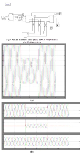
Fig 4 Matlab circuit of three-phase TDVR compensated distribution system
(a)
(b)
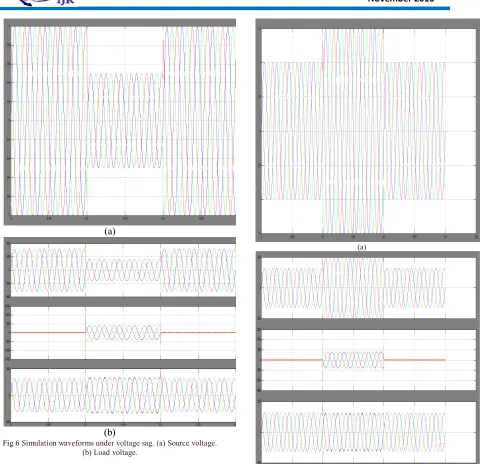
(a)
(b)
Fig 6 Simulation waveforms under voltage sag. (a) Source voltage. (b) Load voltage.
(a)
(b)
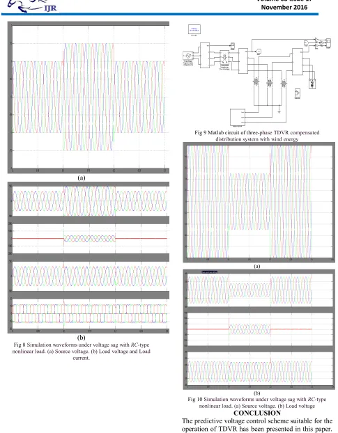
(a)
(b)
Fig 8 Simulation waveforms under voltage sag with RC-type nonlinear load. (a) Source voltage. (b) Load voltage and Load
current.
Fig 9 Matlab circuit of three-phase TDVR compensated distribution system with wind energy
(a)
(b)
Fig 10 Simulation waveforms under voltage sag with RC-type nonlinear load. (a) Source voltage. (b) Load voltage
CONCLUSION
model of the system in modern DSP processor. The simulation and experimental results confirm the usefulness of this scheme. The proposed system for this TDVR is renewable energy source with wind energy
REFERENCES
[1] M. Bollen, Understanding Power Quality
Problems. Piscataway, NJ,USA: IEEE Press, 2000.
[2] K. Karanki, G. Geddada, M. K. Mishra, and B. Kumar, “A modified threephase four-wire UPQC topology with reduced dc-link voltage rating,”IEEE
Trans. Ind. Electron., vol. 60, no. 9, pp. 3555–3566,
Sep. 2013.
[3] M. Moradlou and H. Karshenas, “Design strategy for optimum rating
selection of interline DVR,” IEEE Trans. Power Del., vol. 26, no. 1,pp. 242–249, Jan. 2011.
[4] S. Sasitharan and M. K. Mishra, “Constant switching frequency bandcontroller for dynamic voltage restorer,” IET Power Electron., vol. 3,no. 5, pp. 657–667, Sep. 2010.
[5] F. BadrkhaniAjaei, S. Afsharnia, A. Kahrobaeian, and S. Farhangi, “Afast and effective control scheme for the dynamic voltage restorer,” IEEETrans. Power Del., vol. 26, no. 4, pp. 2398–2406, Oct. 2011. [6] P. Kanjiya, B. Singh, A. Chandra, and K. Al-Haddad, “‘SRF theory revisited’ to control self-supported Dynamic Voltage Restorer (DVR)
forunbalanced and nonlinear loads,” IEEE Trans. Ind.
Appl., vol. 49, no. 5,pp. 2330–2340, Sep./Oct. 2013.
[7] W. Santos et al., “The transformerless single phase universal active power filter for harmonic and
reactive power compensation,” IEEE Trans.
PowerElectron., vol. 29, no. 7, pp. 3563–3572, Jul.
2014.[8] B. H. Li, S. Choi, and D. Vilathgamuwa, “Transformerless dynamic voltage restorer,” Proc.
Inst. Elect. Elec.—Gen. Transmiss.Distrib., vol.
149,no. 3, pp. 263–273, May 2002.
[9] A. Ghosh and G. F. Ledwich, Power Quality
Enhancement Using CustomPower Devices. Boston,
MA, USA: Kluwer, 2002.
[10] C. Rojas et al., “Predictive torque and flux control without weighting factors,” IEEE Trans. Ind.
Electron., vol. 60, no. 2, pp. 681–690,Feb. 2013.[11]
Z. Song, C. Xia, and T. Liu, “Predictive current control of three-phasegrid-connected converters with constant switching frequency for windenergy systems,” IEEE Trans. Ind. Electron., vol. 60, no. 6, pp. 2451– 2464, Jun. 2013.
[12] R. Portillo, S. Vazquez, J. Leon, M. Prats, and L. Franquelo, “Model based adaptive direct power control for three-level NPC converters,” IEEETrans.
Ind. Informat., vol. 9, no. 2, pp. 1148–1157, May
2013.
[13] J. Moreno, J. Huerta, R. Gil, and S. Gonzalez, “A robust predictive current control for three-phase grid-connected inverters,” IEEE Trans. Ind.Electron., vol. 56, no. 6, pp. 1993–2004, Jun. 2009.
[14] P. Cortes, M. Kazmierkowski, R. Kennel, D. Quevedo, and J. Rodriguez
“Predictive control in power electronics and drives,”
IEEE Trans. Ind. Electron., vol. 55, no. 12, pp.
4312–4324, Dec. 2008.
[15] P. Cortes, J. Rodriguez, D. Quevedo, and C. Silva, “Predictive current control strategy with imposed load current spectrum,” IEEE Trans.
PowerElectron., vol. 23, no. 2, pp. 612–618, Mar.
2008.[16] E. Wu and P. Lehn, “Digital current control of a voltage source converterwith active
damping of LCL resonance,” IEEE Trans. Power
Electron., vol. 21, no. 5, pp. 1364–1373, Sep. 2006.
[17] L. Hang, S. Liu, G. Yan, B. Qu, and Z.-yu Lu, “An improved deadbeat
scheme with fuzzy controller for the grid-side
three-phase PWM boostrectifier,” IEEE Trans. Power
Electron., vol. 26, no. 4, pp. 1184–1191,Apr. 2011.
[18] O. Kukrer and H. Komurcugil, “Deadbeat control method for single phase UPS inverters with compensation of computation delay,” Proc. Inst.
Elect.Eng.—Elect. Power Appl., vol. 146, no. 1, pp.
123–128, Jan. 1999.
[19] J. Holtz et al., “Design of fast and robust current regulators for high-power drives based on complex state variables,” IEEE Trans. Ind. Appl., vol. 40,no. 5, pp. 1388–1397, Sep./Oct. 2004.
[20] O. Kukrer, “Discrete-time current control of
voltage-fed three-phase PWM inverters,” IEEE
Trans. Power Electron., vol. 11, no. 2, pp. 260–269,
Mar. 1996.
[21] J. Rodriguez et al., “Predictive current control of a voltage source inverter,” IEEE Trans. Ind.
Electron., vol. 54, no. 1, pp. 495–503, Feb. 2007.
[22] C. Zhan et al., “Software phase-locked loop applied to Dynamic VoltageRestorer (DVR),” in
Proc. IEEE Power Eng. Soc. Winter Meet., 2001,vol.
3, pp. 1033–1038.Chandan Kumar(S’13) received the B.Sc. degree in electrical engineering from