Using Self-Synchronization Error Dynamics Formulation Based Controller for Maximum
Photovoltaic Power Tracking in Micro-Grid Systems
1
SEGU NIKHILA, 2 B.PARAMESWARA REDDY M.Tech
1
M.Tech Dept of EEE (PED), St.Mark Group of Educational Institutions, Affiliated to JNTUA, AP, India 2
Assistant Professor, Dept of EEE (PED), St.Mark Group of Educational Institutions, Affiliated to JNTUA, AP, India
Abstract--
In this we propose maximum photovoltaic power tracking (MPPT) for the photovoltaic (PV) array by using Fractional-order incremental conductance method (FOICM). The PV array has low conversion efficiency & the output vigour of PV array relies on the operation, comparable to distinct sunlight radiation, atmosphere temperature, and weather conditions. Highest charging power may also be extended to a battery making use of a MPPT algorithm. The energy conversion of the absorbed sunlight mild and temperature is straight transferred to the semiconductor, however electricity conduction has anomalous diffusion phenomena in inhomogeneous fabric. FOICM can provide a dynamic mathematical model to describe non-linear characteristics. The fractional-order incremental exchange as dynamic variable is used to adjust the PV array voltage toward the maximum vigour point. For a small-scale PV conversion process, the proposed method is validated by simulation with one-of-a-kind operation environments.1. Introduction:
The everincreasing demand for low -cost energy and growing concern about environmental issues has generated enormous interest in the utilization of nonconventional energy sources such as the solar energy. The freely and abundantly available solar energy can be easily converted into electrical energy using photovoltaic (PV) cells. A PV source has the advantage of low maintenance cost, absence of moving/rotating parts, and pollution-free energy conversion process. However, High initial capital cost has been another hurdle in the
popularity of PV systems. These drawbacks notwithstanding, the PV systems have emerged as one of the most popular alternatives to conventional energy, A major challenge in the use of PV is posed by its nonlinear Current– voltage (I–V) characteristics, which result in a unique maximum power point (MPP) on its power–voltage (P–V) curve. The best known MPPT classic algorithms are Perturb-and-observe (P&O) and incremental conductance (Inc. Cond.).
2. Mathematical Model
The building block of PV arrays is the solar cell, which is basically a p-n semiconductor junction, shown in Figure 1. The V-I characteristic of a solar array is given by Eq. (1) [4]. sh s s o sc R IR V NKT IR v q I I
I exp ( 1( )
(1)
where V and I represent the output voltage and current of the PV, respectively; Rs and Rsh are
the series and shunt resistance of the cell; q is the electronic charge; ISC is the light-generated
current; Iois the reverse saturation current; n is a
dimensionless factor; k is the Boltzmann constant, and Tk is the temperature in
Figure 1 p-n semiconductor junction
Equation (1) was used in computer simulations to obtain the output characteristics of a solar cell, as shown in Figure 2. This curve clearly shows that the output characteristics of a solar cell are non-linear and are cru-cially influenced by solar radiation, temperature and load condition. Each curve has a MPP, at which the solar array operates most efficiently.
Figure 2. V-I characteristic of a solar cell.
MPPT methods:
The Perturb and Observe method:
The Perturb and Observe algorithm is a simple technique for maximum power point tracking. It is based on controlling the duty cycle (d) of a dc-dc converter to adjust the PV array terminal voltage at the maximum power point [14]. The power output of the array is monitored every cycle and is compared to its value before each perturbation is made. If a change (either positive or negative) in the duty cycle of the dc-dc converter causes output power to increase, the duty cycle is changed in the same direction. if it causes the output power to decrease, then it is reversed to the opposite direction. The performance of the algorithm is affected by the choice of the perturbation magnitude (Δd) of the converter switching duty cycle. Large perturbations cause large output power fluctuations around the MPP while small perturbations slow down the algorithm. Modifications to this technique are published in
[15], [16] and [17] to improve performance while maintaining the basic principle of operation. Illustrates the operation sequence of the algorithm.
Incremental Conductance Method
The method is based on the principle that the slope of the PV array power curve is zero at the maximum power point.
0
dV
dP
left of MPPV
0 dV dP
right of MPPV
0 dV dP at MPPV Since, dV dI V I dV dI V I dV IV d dV dP ( )
Equation (1) can be rewritten as,
V I dV
dI
right of MPPV
V I dV
dI
left of MPPV
V I dV
dI
at MPPV
decides the Maximum force point procedure has come to the most extreme force point and quit annoying the working point. .
One weakness of this calculation is the expanded many-sided quality when contrasted with P&O. Fig 1.demonstrating the flowchart of Incremental conductance, in which incremental conductance is contrasted and quick conductance and subsequently most extreme force point is followed. Addition size decides the how quick most extreme force point is followed. Optimizing can be accomplished with greater augmentations yet the framework won't not work precisely at the most extreme force point and sway about. This system has complex hardware; exactness of the strategy relies on upon the emphasis size, which is typically altered for the traditional incremental conductance technique.
Flow chart for FOICM method:
Fig. 3:Flow chart of FOICM MPPT Algorithm
Table 1: Comparison between different MPPT methods
The main advantage of the FOIC method is that it offers a good yield under rapidly changing atmospheric conditions. In addition, it has lower oscillation around the MPP as compared to the P&O method. The MPPT efficiencies of the IC and P&O methods are, essentially, the same. However, implementing the methods in hardware it requires complex control circuit which may result in high cost.
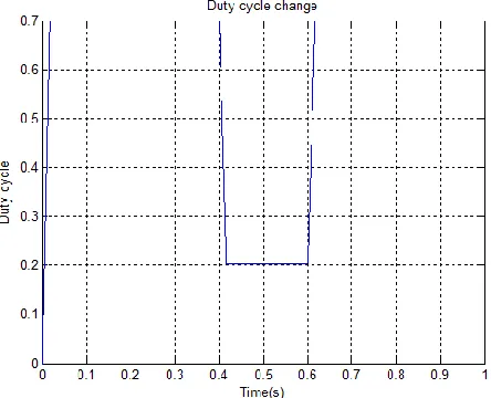
Fig. 4 Duty cycle response curve with the proposed method.
calculate quickly and at t=0.6 s, another value of insolation is applied from 400 w/m2 to 1000 w/m2), that is to say two abrupt changes are made in a short period and duty cycle adjusted to go well with MPP. So we can see that the proposed algorithm follow MPP high precision and it is capable to give the response in short time.
Simulink modle:
Fig 5: Simulink circuit for FOICM
Simulink resul ts:
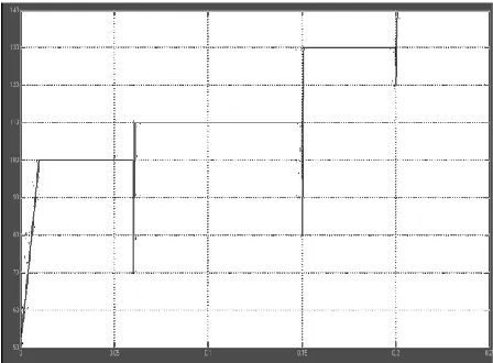
Graph.1: As the time gradually increases the temperature also increases from 38 deg to 42 deg in steeped distribution and the MPPT tracks the maximum power at each disturbance.
Graph.2: As the temperature increases the radiation gradually increases from 0.1kW/m2 to 1kW/m2 steeped distribution and the MPPT tracks the maximum power at each disturbance.
Graph.4: This graph represents the Duty cycles versus the Tracking cycles for achieving the maximum power tracking. The pulses indicate that turn ON and turn OFF time of the MPPT boost converter.
Graph.5: For a fractional order error the behavior of the FOICM MPPT, (the iterations are also less compared to the P&O method) to perform self synchronization.
Graph.6: In same FOICM method for same
temperature and radiation we observe the maximum
tracking of the power from solar panels without any
fluctuations
CONCLUSION & FUTURE SCOPE
The Fractional-order Incremental conductance method (FOICM)used in this paper is applicable to any general MPPT methods.
When a cell temperature sensing element and a voltage detector are added to the posterior pole. This method improves the oscillation of a PV power system during steady-state response. According to the simulation results, the system still tracks the steady-state power at MPP, though as the cell temperature changes the voltage oscillation amplitude is reduced. The experimental results prove the feasibility and effectiveness of the Fractional-order Incremental conductance method proposed in this paper. From the steady-state responses of MPPT, it can be seen vibration amplitude can be suppressed with control action. Therefore, the steady-state vibration energy can be saved. Therefore, the oscillation amplitude of voltage when the PV power system is in steady state is reduced, the Dynamic error is reduced effectively and the service life of electronic modules can be prolonged. The efficiency of the PV conversion system is improved for standalone systems or for grid-connected distribution systems, such as battery charging, home power supply, and low voltage local loads.
In order to avoid the PV system having power oscillation near the MPP during steady state response we can combine our MPPT control of Fractional order incremental conductance method with New dynamic error detector The voltage from the PV panels is captured and calculated by MPPT controller. The result is extracted to the New synchronization dynamic error detector to adjust the PWM signal to control the PWM duty ratio of DC/DC converter.
REFERENCES
[1] Ibrahim, H. E.-S. A. and Houssiny, F. F., “Microcom-puter Controlled Buck Regulator for Maximum Power Point Tracker for DC Pumping System Operates from Photovoltaic System,” Proceedings of the IEEE Inter-national Fuzzy Systems Conference, August 22 25, Vol. 1, pp. 406 411 (1999).
Tracker for Photovoltaic Applications,” Proceedings of the IEEE Power Electronics Specialists Conference, PESC, Vol. 2, pp. 1710 1716 (1996).
[3] Enslin, J. H. R. and Snyman, D. B., “Simplified Feed-Forward Control of the Maximum Power Pont in PV Installations,” Proceedings of the IEEE International Conference on Power Electronics Motion Control, Vol. 1, pp. 548 553 (1992).
[4] Bose, B. K., Szczeny, P. M. and Steigerwald, R. L., “Microcomputer Control of a Residential Photovoltaic Power Conditioning System,” IEEE Transactions on Industrial Electronics, Sept./Oct., Vol. IA-21, pp. 1182 1191 (1985).
[5] C.-H. Lin, C.-H. Huang, Y.-C. Du, and J.-L. Chen, “Maximum photovoltaic power tracking for the PV array using the fractional-order incremental conductance method,” Appl. Energy, vol. 88, no. 12, pp. 4840–4847, Dec. 2011.