Test Station for Measuring Electromechanical
Relay Parameters Using Microcontroller
Arunima Manuel
1, Vineetha S
2, Mary Roy
3PG Student [Applied Electronics], Dept. of ECE, MG University College of Engineering, Thodupuzha, Kerala, India1
Scientist/Engineer “SE” ,QDAC/QRAG/SR/VSSC ,Trivandrum, Kerala, India2
Division Head, QDAC/QRAG/SR/VSSC Trivandrum, Kerala, India3
ABSTRACT: This paper describes a test station for measuring of electromechanical relay parameters using PIC18F6520 microcontroller. The main component of the proposed system is microcontroller, interfaced to a PC through I/O card. The front end of the proposed system is realized in Visual Basic. The parameters, namely coil resistance, contact resistance, pull-in and dropout voltage, operate time and release time, bounce time are measured by using this test station. This system is capable of measuring parameters of both latching and non latching electromechanical relays with up to 8 poles. All defined parameters are measured within 30 Sec. It is based on Graphical User Interface and is user friendly. A single jig is suitable for all types of relays. The pull-in voltage and dropout voltage are measured with resolution of the order of µV. The operate time and release time are measured with resolution of the order of ns .The proposed paper introduces the hardware structure and the software process of the testing system.
KEYWORDS: PIC18F6520, Visual basic, coil resistance, contact resistance, operate and release time, bounce time, pull-in and dropout voltage.
I.INTRODUCTION
Electromechanical relays are widely used in electronic systems. The parameters such as voltage and time of the relay are used to ensure a product’s quality. Electromechanical relays are switches needed for controlling high current, high voltage loads by a small controlling power. Galvanic isolation is provided between the input and load. Above mentioned relays offer contact resistance of the order of milliohm and no OFF state leakage current. The important parameters of an electromechanical relay are coil resistance, contact resistance, pull-in and dropout voltage, operate and release time and bounce time. This paper describes a test station for relay for the above said parameters.
Coil resistance is the electrical resistance of the relay coil at reference temperature. It varies with temperature and is expressed in Ω. The resistance between the contacts is named as Contact resistance, expressed in mΩ in the closed state. Operate time is the time that elapses between, the instant power is applied to a relay coil and the moment the contacts are closed. Release time is the elapsed time between the instant power is removed from a relay coil and the moment the contacts have opened. Bounce means intermittent opening and closing of contacts caused by abrupt application or removal of power to or from the relay coil.
Five 8 bit I/O ports , Serial port and Interrupt modules of PIC microcontroller are used for communicating with a PC, polling closure status of DUT’s contacts, controlling coil voltage etc.
II. LITERATURE REVIEW
ISSN (Print) : 2320 – 3765 ISSN (Online): 2278 – 8875
I
nternational
J
ournal of
A
dvanced
R
esearch in
E
lectrical,
E
lectronics and
I
nstrumentation
E
ngineering
(An ISO 3297: 2007 Certified Organization) Vol. 4, Issue 8, August 2015
III. BLOCK DIAGRAM OF TEST STATION
Fig.1 Block diagram of the test station.
PIC is the main controller. PC is interfaced to the microcontroller through 48 channel I/O card. The coil voltage of the relay is controlled by PC through a dual DAC. The resolution of the DAC is 12 bits. The output of the DAC drives a power amplifier which in turn drives the coil of the DUT. The Pull-in voltage and dropout voltage are measured by controlling the coil voltage through the DAC and polling the open and close status of contacts through the I/O port of PIC.
RAM is used to store the status of the contacts, it is a depth of 512 K. The system capable of acquiring the contact status at a sampling rate of 50 ns. This enables to measure of bounce of the chatter in the order of ns. The write/ read of RAM is controlled by PIC. Serial ports of PIC, interrupt modules and I/O ports of PIC microcontroller are made use of. The results are printed out by printer.
1. Pull-in and Dropout Voltage:
Method: Increase the electromechanical relay coil voltage linearly till all NO contacts get closed. That particular coil voltage where all the NO contacts get closed is the pull-in voltage. Fig.2 shows the procedure diagram of Pull-in voltage.
The electromechanical relay coil voltage is decreased linearly till all NO contacts get opened. The precise voltage where all the NO contacts get opened is the dropout voltage.
Fig.2 Pull-in voltage procedure diagram.
ISSN (Print) : 2320 – 3765 ISSN (Online): 2278 – 8875
I
nternational
J
ournal of
A
dvanced
R
esearch in
E
lectrical,
E
lectronics and
I
nstrumentation
E
ngineering
(An ISO 3297: 2007 Certified Organization) Vol. 4, Issue 8, August 2015
2. Coil resistance:
Coil resistance is measured by using 6½-Digit Multimeter which is interfaced through GPIB cable to the DUT. Through switches in the block diagram (Fig.1) the coil ends of DUT are connected to DMM.
3. Contact resistance:
A known current is forced to the closed contacts of the DUT. Through DAC, maximum coil voltage is forced from PC. DMM is used to measure the voltage across the contact. Contact resistance=voltage measured /forced current.
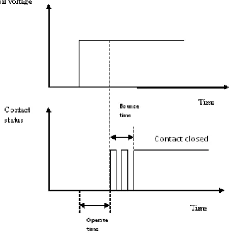
4. Operate Time:
Operate time is the time that elapses between, the instant power is applied to a relay coil and the moment the contacts are closed. Fig. 4 shows the Operate time and operate bounce time.
Fig. 4 Operate time
Fig.5 Operate time procedure diagram.
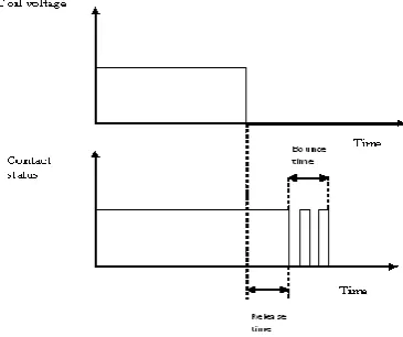
5. Release time:
ISSN (Print) : 2320 – 3765 ISSN (Online): 2278 – 8875
I
nternational
J
ournal of
A
dvanced
R
esearch in
E
lectrical,
E
lectronics and
I
nstrumentation
E
ngineering
(An ISO 3297: 2007 Certified Organization) Vol. 4, Issue 8, August 2015
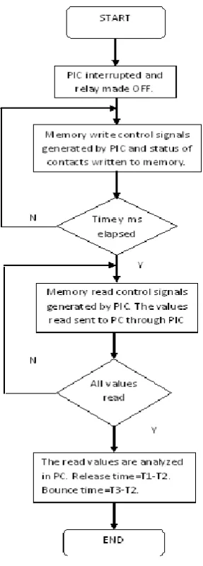
Method: PIC is interrupted. The relay made OFF from PC via DAC, at time T1. The status of contacts is polled and written onto a RAM. Control signals of the memory are generated by PIC in the interrupt service routine and the process is continued for y ms. The instant at which the contact starts to open (bounce starts) is T2. The instant at which the contact is fully opened is at T3. Then release time=T1-T2. And the release bounce time is T3-T2 is shown in fig.7.
IV. RESULT AND DISCUSSION
Fig.5 Human-computer interaction interface.
V. CONCLUSION
The testing system uses a single-chip microcomputer as the core, realizes the parameter testing of electromechanical relay, and makes the testing of relay parameter more accurate. In the testing of the relay parameters, the time approaches to 30 sec. The graphical user interface, visual basic in testing system reflects the intelligence and user-friendliness of the testing. The device has an efficient man machine interface along with a low cost, high accuracy and high level performance.
REFERENCES
[1] Mohammad Ali Mazidi, Rollin.D.Mckinlay, Danny Causey, “PIC Microcontroller and Embedded Systems using assembly and C for PIC18F”. [2] Scott Warner, “Teach yourself Visual Basic 6.0”.
[3]Taihang Du, Ling Qi, Yongsheng Chen etc. ”Detecting Technology of Electromagnetic Relay Parameters Based on SCM,” second International Conference on intelligent Networks and Intelligent Systems,2009.
[4] Deitel and Deitel Staff, Nieto, T. R., Deitel, Harvey M. “Visual Basic 6 How to Program”. [5] Sprague, Phillips, Sprague, Michael “Microsoft Visual Basic 6.0 Introduction to Programming”. [6] Datasheets - GPIB (NI-488) manual, DMM-2000 Manual, PIC18F6520.
BIOGRAPHY