Three-phase Transformerless Grid
connected
PV Inverter
RONANKI ADARSH KUMAR M-tech Student Scholar
Department of Electrical & Electronics Engineering, Baba Institute of Technology and Sciences, P.M.Palem;
Visakhapatnam(Dt); Andhra Pradesh, India.
M.V.S.PREM SAGAR Assistant Professor
Department of Electrical & Electronics Engineering, Baba Institute of Technology and Sciences, P.M.Palem;
Visakhapatnam(Dt); Andhra Pradesh, India.
Abstract: PV systems are now more affordable due to government
incentives, advancement of power electronics and semiconductor technology and cost reduction in PV modules. In the past, various transformers less PV inverter topologies have been introduced, with leakage current minimized by the means of galvanic isolation and common-mode voltage (CMV) clamping. Leakage current minimization is one of the most important considerations in transformer less photovoltaic (PV) inverters. The galvanic isolation can be achieved via dc-decoupling or ac-decoupling, for isolation on the dc- or ac-side of the inverter, respectively. It has been shown that the latter provides lower losses due to the reduced switch count in conduction path. Common-mode voltage (CMV) appears in Three-phase due to working principles of the pulse width modulation (PWM) inverters. This voltage is the main source of many unwanted problems systems. In this Project, several recently proposed transformer less PV inverters with different galvanic isolation methods and CMV clamping technique are analyzed and compared. A simple modified H-bridge zero-voltage state rectifier is also proposed, to combine the benefits of the low-loss ac-decoupling method and the complete leakage current elimination of the CMV clamping method. The performances of different topologies, in terms of CMV, leakage current, total harmonic distortion, losses and efficiencies are compared. A safety issue is the main concern for the transformer less PV systems due to high leakage current. Without galvanic isolation, a direct path can be formed for the leakage currentto flow from the PV to the grid The proposed concept can be implemented to PV inverter with Three-phase by using MATLAB/SIMULATION software.
Keywords:Common Mode Voltage,Leakage Currentphotovoltaic (PV) system.
I. INTRODUCTION
Today, the energy demand is increasing due to the rapid increase of the human population and fast-growing
filter inductors are required, increasing the cost and size of the PV systems. Hence, many research works have been proposed recently to eliminate the leakage current via galvanic isolation and CMV clamping techniques. Galvanic isolation topologies such as H5, H6 family and HERIC introduce dc-decoupling and ac-decoupling to disconnect the PV and the grid. It is found that ac-decoupling provides lower losses due to reduced switch count in the conduction path. Nevertheless, the galvanic isolation alone cannot completely eliminate the leakage current due to the influence of switches’ junction capacitances and parasitic parameters. Therefore, CMV clamping has been used in oH5, and H-bridge zero-voltage
(a)
(b)
(c)
(d)
(f)
Fig. 1.Recently proposed transformerless topologies. (a) Diode-clamped topology. (b) H5 topology. (c) HERIC topology. (d)
oH5 topology. (e) H6 topology. (f) HBZVR topology.
state rectifier (HBZVR), as shown in Fig. 1(d)–(f), to completely eliminate the leakage current. However, the clamping branch of HBZVR does not perform optimally. It is shown in the later section that the leakage current is as high as those of galvanic isolation topologies. In this paper, several recently proposed transformerless PV inverters with different galvanic isolation methods and CMV clamping techniques, as shown in Fig. 1, are analyzed and compared. A simple modified HBZVR-D is also proposed, to combine the benefits of the low-loss ac-decoupling method and the complete leakage current elimination of the CMV clamping method. Performance of HBZVR-D is compared to other existing topologies in terms of CMV, leakage current, total harmonic distortion (THD), losses analysis, and efficiency. Discussions are done based on MATLAB/Simulink simulations and further validated through experimental tests. It is proven that HBZVRD topology gives the best overall performance and is suitable for transformerless PV applications. This paper is organized as follows: Leakage current reduction methods via galvanic isolation and CMV clamping is discussed and analyzed in Section II. Proposed topology with its conversion structure and operation principles is presented in Section III.
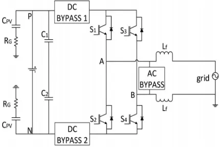
When the transformer is removed from the inverter, a resonant circuit is formed as shown in Fig. 2(a). This resonant circuit includes stray capacitance (CP V ), the filter inductors (L1 and L2), and leakage current (IL). Here, the power converter is represented by a block with four terminals to allow a general representation of various converter topologies. On the dc side, P and N are connected to the positive and negative rail of the dc-link, respectively; while on the ac side, terminals A and B are connected to the single-phase grid via filter inductors. From the view point of the grid, the power converter block shown
(a)
the conversion structure, this power converter block can be simplified into the equivalent circuit which consists of VAN and VBN as shown in Fig. 2(b) . The leakage current is thus a function of VAN, VBN, grid voltage, filter inductance, and stray capacitance. The CMV VC
M and differential-mode voltage VDM can be defined as
(1)
(2)
Rearranging (1) and (2), the output voltages can be expressed in terms of VC M and VDM as
(3)
(4)
Using (3)–(4) and considering only the common-mode components of the circuit, a simplified common-mode model can be obtained as in , following the steps in and The equivalent CMV (VEC M ) is defined as
(5)
Since identical filter inductors (L1 = L2) are used in this paper, the VEC M is equal to VC M
(6)
From the model, it can be concluded that the leakage current is very much dependent of the CMV. Thus, converter structure and the modulation technique must be designed to generate constant CMV in order to
eliminate the leakage current. It is worth highlighting that the model in Fig. 2(c) has been commonly used for describing the common-mode behaviour of the conventional full-bridge (H4) topology. However, due to the generality of the model, it is obvious that the model is valid for other topologies discussed here, apart from H4. As a matter of fact, the same model has been used to analyze the common-mode behaviour of various transformersless converter topologies. However, since different topology has different VAN and VBN , the expressions for VC M and VDM will differ from one another, which yield different common-mode behaviour.
Fig. 3.Universal transformerless topologies.
Hence, to evaluate the common mode behaviour of a particular topology,VANandVBN under different switching condition need to be evaluated, as will be shown later.
the ac side of the inverter (i.e., ac-decoupling method) such as seen in HERIC. This ac-bypass branch functions as a freewheeling path which is completely isolated from the conduction path, as shown in Fig. 3. As a result, the output current flows through only two switches during the conduction period. Therefore, topologies employing ac-decoupling techniques are found to be higher in efficiency as compared to dc-decoupling topologies. One setback of galvanic isolation is that there is no way of controlling the CMV by PWM during the freewheeling period. Fig. 4 shows operation modes of galvanic isolation which
(a)
(b)
Fig. 4.Operation modes of dc-decoupling topology. (a) Conduction mode and (b) freewheeling mode
employs dc-decoupling method. As shown in Fig. 4(a), during the conduction period, S1 and S4 conduct to
(7)
Nevertheless, during the freewheeling period, the dc-bypass switches disconnect the dc-link from the grid. Therefore, point A and point B are isolated from the link, and VA and VB are floating with respect to the dc-link as shown in Fig. 4(b). The CMV during this period of time is not determined by the switching state, but instead, is oscillating with amplitude depending on the parasitic parameters and the switches’ junction capacitances of the corresponding topology. As a result, leakage current can still flow during freewheeling period. The same is the case for converters using ac decoupling methodB. CMV ClampingAs mentioned earlier, CMV is one of the main causes for leakage current. H5 and HERIC focus only on providing galvanic isolation while neglecting the effect of the CMV. Unlike conventional topologies, the CMV in these topologies cannot be manipulated via PWM, due to the use of galvanic isolation as explained previously. In order to generate constant CMV, clamping branch is introduced in oH5 [see Fig. 1(d)] and H6 [see Fig. 1(e)].
and CMV clamping, leakage current is completely eliminated. Nevertheless, both H6 and oH5 uses dc-decoupling method, which suffers from lower efficiency. HBZVR also employs CMV clamping technique but it is found that the clamping branch does not function optimally. It is shown in both the simulation and experimental results that the CMV and the leakage current in HBZVR are as high as those in the topologies which use only galvanic isolation.
III. OPERATION PRINCIPLES OF PROPOSED TOPOLOGY
A. Structure of Proposed HBZVR-D
Based on the analysis above, a simple modified HBZVR-D is proposed to combine the benefits of the low-loss ac-decoupling method and the complete leakage current elimination of the CMV clamping method. HBZVR-D is modified by adding a fast-recovery diode, D6, to the existing HBZVR as shown in Fig. 5(a). The voltage divider is made up of C1 and C2.
S1−S4 are the switches for full-bridge inverter. The antiparallel diodes, D1−D4, as well as S5 provide a freewheeling path for the current to flow during the freewheeling period. Diodes D5 and D6 form the
clamping branches of the freewheeling path.
B. Operation Modes and AnalysisIn this section, the operation modes and the CMV of the proposed topology is discussed. Fig. 5(b) illustrates the switching
(a)
(b)
(c)
(d)
Fig. 6.Operation modes of proposed HBZVR-D topology.(a) Mode 1—conduction mode and (b) Mode 2—freewheeling mode during positive half cycle. (c) Mode 3—conduction mode and (d) Mode 4—
freewheeling mode during negative half cycle.
patterns of the proposed HBZVR-D. Switches S1−S4 commutate at switching frequency to generate unipolar output voltage. S5 commutates complementarily to
flows through S1 and S4. VAB = +VDC . The CMV becomes
(8)
In mode 2, S1−S4 are OFF. S5 is ON to create a freewheeling path. Current decreases and freewheels through diodes D3,D2, and the grid. The voltage VAN decreases and VBN increases until their values reach the common point, VDC /2, such that VAB = 0. The CMV is
(9)
In mode 3, S2 and S3 are ON, while S1,S4 and S5 are OFF. Current increases and flows through S2 and S3. VAB = −VDC . The CMV becomes
(10)
In mode 4, S1−S4 are OFF. S5 is ON to create freewheeling path. Current decreases and freewheels through diodes D1,D4, and the grid. The voltage VAN decreases and VBN increases until their values reach the common point, VDC /2, and VAB = 0. The CMV is as derived in (10). Obviously, modulation techniques are designed to generate constant CMV in all four operation modes. All the research works are designed based on the principles above. Practically, VAN and VBN do not reach common point during the freewheeling period (mode 2 and mode 4). It is shown in simulation and experimental results later that the CMV is not constant without clamping branch. During the freewheeling
relatively higher efficiency than those of dc-decoupling topologies.
C. Operation Principles of Improved Clamping Branch
During the freewheeling period, S5 is turned ON, connecting point A and B. Freewheeling path voltage VF P can be defined as VF P =VAN ≈VBN , since the voltage drops across diodes and S5 are small compared to VDC . There are two possible modes of operation (mode 2 and mode 4 as shown in Fig. 6) depending on whether D5 or D6 is forward biased. When VF P is greater than VDC /2, D5 is forward biased and D6 is reversed biased. Current flows from the freewheeling path to the midpoint of the dc-link via the clamping diode D5, as shown in Fig. 6(b), which completely clamps the VF P to VDC /2. On the other hands, when the VF P is less than VDC /2, D6 is forward biased and
D5 is reversed biased. As shown in Fig. 6(d), current flows from the midpoint of the dc-link to the freewheeling path via the added clamping diode D6, to increase the VF P to VDC /2. It should be noted that during the dead time between the conduction period and freewheeling period, the freewheeling path is not well-clamped and the CMV can be oscillating with the grid voltage. Nevertheless, with proper selection of dead time, this effect can be minimized. In HBZVR, the clamping branch consists of D5 only. Thus, the clamping of the freewheeling path is limited only for the period when VF P is more than VDC /2. When VF
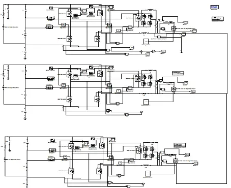
Fig.7. Simulation block diagram of three-phase controller
Fig 8.simulation wave form of three-phase grid voltage,
Fig9.Simulation wave form of three-phase grid current
Fig 10.simulation wave form of three-phase current and voltage
V. CONCLUSION
This paper presents the comparison and analysis of the single phase and three phase transformer less pv inverter. With the understanding on the merits and demerits of the different approaches, a modified HBZVR topology is obtained by addition of a fast-recovery diode. The proposed topology (known as HBZVR-D) combines the advantages of the low- loss ac-decoupling method and the complete leakage current elimination of the CMV clamping method. The performance of the transformerless topologies, including the proposed HBZVR-D, is compared in terms of CMV, leakage current, losses, THD, and
efficiency. Further we implement the same system in
three phase and we will have three phase grid voltage, currents and simulation results of the grid current and voltages. The proposed system will be implemented in the matlab/ simulink environment.
VII.REFERENCES
[1]Tan KhengSuan Freddy, Nasrudin A. Rahim, Senior
Member, IEEE, Wooi-Ping Hew, Member, IEEE,”
Comparison and Analysis of Single-Phase Transformerless Grid-Connected PV Inverters” IEEE TRANSACTIONS on power electronics, vol. 29, no. 10, october 2014
[2] F. T. K. Suan, N. A. Rahim, and H. W. Ping, “Modelling, analysis and control of various types of transformer less grid connected PV inverters,” in Proc. IEEE Clean Energy
Technol., Jun. 2011, pp. 51–56.
[3] N. A. Rahim, K. Chaniago, and J. Selvaraj, “Single-phase seven-level grid connected inverter for photovoltaic system,”
IEEE Trans. Ind. Electron., vol. 58, no. 6, pp. 2435–2443,
Jun. 2011.
[4] G. Petrone, G. Spagnuolo, R. Teodorescu, M. Veerachary, and M. Vitelli, “Reliability issues in photovoltaic power processing systems,” IEEETrans. Ind. Electron., vol. 55, no. 7, pp. 2569–2580, Jul. 2008.
[5] M. Calais, J. Myrzik, T. Spooner, and V. G. Agelidis, “Inverters for single phase grid connected photovoltaic system – an overview,” in Proc. IEEEPower Electron. Spec. Conf., 2002, pp. 1995–2000.
[6] J. M. Shen, H. L. Jou, and J. C. Wu, “Novel transformer lessgrid connected power converter with negative grounding for photovoltaic generation system,” IEEE Trans. Power
Electron., vol. 27, no. 4, pp. 1181– 1829, Apr. 2012.
grid-connected photovoltaic systems,”IEEE Trans. Ind. Electron., vol. 57, no. 9, pp. 3118–3128, Sep. 2010.
[8] O. Lopez, F. D. Freijedo, A. G. Yepes, P. Fernandez-Comesaa, J. Malvar, R. Teodorescu, and J. Doval-Gandoy, “Eliminating ground current in a transformer less photovoltaic application,” IEEE Trans. Energy Convers., vol. 25, no. 1, pp. 140–147, Mar. 2010.
[9] T. Kerekes, R. Teodorescu, M. Liserre, C. Klumpner, and M. Sumner, “Evaluation of three-phase transformer less photovoltaic inverter topologies,” IEEE Trans. Power
Electron., vol. 24, no. 9, pp. 2202–2211, Sep. 2009.
[10] B. N. Alajmi, K. H. Ahmed, G. P. Adam, and B. W. Williams, “Singlephase single-stage transformer less grid-connected PV system,” IEEETrans. Power Electron., vol. 28, no. 6, pp. 2664–2676, Jun. 2013.