Analysis and Design of Low Pass Filter by
Using DGS for WLAN Application
Aanshi Jain1, Anjana Goen2
M.Tech Scholar, Dept. of ECE, Rustam Ji Institute of Technology, Tekanpur, Gwalior, India1
Associate Professor, Dept. of ECE, Rustam Ji Institute of Technology, Tekanpur, Gwaliore, India2
ABSTRACT: The performance of Butterworth low pass filter (LPF) with defected ground structure (DGS) is studied and simulated. Calculation and comparison of the response of low pass filter (LPF) with and without using defected ground structure (DGS) was done. The proposed DGS cell provides low-pass characteristic whose cutoff frequency could be changed by tuning its dimensions. Results are simulated using computer simulation technology software (CST). In this paper, 5th order stepped impedance low pass microstrip line filter have been designed at 5.6 GHz frequency and implemented on FR4 substrate of relative permittivity is 4.3. The undesired sidebands and fluctuations of response are reduced by using defected ground structure (DGS).
KEYWORDS: Low Pass Filter (LPF), Defected Ground Structure (DGS), Microstrip Stepped Impedance Filter, Butterworth Low Pass Filter.
I. INTRODUCTION
Defected ground structure for microstrip line was most common topic for research at recent year. They are giving a lot of different structure for implementing DGS [1]. Microwave filter designs have been at the forefront of research in both industry as well as in academia due to increasing specification levels and demand for advanced communication systems.
In addition to PBG (photonic bandgap) and EBG (electromagnetic bandgap) structure, DGS was created by etching different shapes in ground plane. Which increase the inductance and capacitance values of microstrip line, so undesired output response fluctuations will be eliminated and the output is sharp stopband in case of LPF [2] and increased bandwidth in case of BSF [3]. DGS has property of neglecting electromagnetic wave in certain frequency and direction, and most important function of these structures is the filtering of frequency bands, and harmonics of the filter in microwave circuit.
The realizable filters that are in common use are Butterworth filter, Chebyshev filter and Bessel filter. Utilization of Butterworth low pass filter exist contradiction problems between test precision, stability and response time. Low order Butterworth low pass filter has rapid response, small overshoot but bad in test precision, while high order Butterworth low pass filter, is good in test precision but has slow response with large overshoot and poor stability [4-5]. The type of construction of this filter is a reflective filter which is consists of capacitive and inductive elements producing ideally the zero reflection loss in the pass band region and very high attenuation in the stop band region [6]. The practical filters have small non-zero attenuation in the pass band, a small signal output in the attenuation or stop band due to the presence of resistive losses in reactive elements of propagating medium [7].
II.FILTERDESIGNPROCEDURE
Figure 1 shows a general structure of the stepped-impedance low pass microstrip filters which use a cascade structure of alternating high and low impedance transmission lines. These are much shorter than the associated guided- wavelength, so as to act as semi lumped elements [8]. The high-impedance lines act as series inductors and the low-impedance lines act as shunt capacitors. Therefore, this filter structure is directly realize the L-C ladder type of lowpass filters of figure 2.
Figure 1 General structure of the stepped-impedance low pass microstrip filter.
Figure 2 L-C ladder type of low pass filter.
LPF was design at the cut off frequency of fc=5.6GHz and formula which is used for the design of LPF is
Synthesis of W/h
ℎ =
8
−2 With
= 60
+ 1
2 .
+ + 1
+ 1 0.23 + 0.11
For W/h>1
=
+
1 + 12
.+
0.04 1
−
Whereas guided wavelength is given by equation given below
ƛ = 300
f(GHz) ε
εre = Effective dielectric constant
Values of inductor and capacitor are given by
C = 1
2 π Z f
g′ ,L = 1 2 π f Z g For i = 1, 2, 3, ... , 6.
Calculation of length of inductor and capacitor is done using formula
= ƛ (f )
2π sin 2 π f
L Z
= ƛ (f )
2 π sin (2π Z C )
III.IMPLEMENTATIONOF5TH
ORDER STEPPEDIMPEDANCE BUTTERWORTHFUNCTIONLOW PASSFILTER
The design of low pass filters involves two main steps. The first one is to select an appropriate low pass prototype. The choice of the type of response, including Pass band ripple and the number of reactive elements will depend on the required specifications.
Element values considered stepped impedance Butterworth function low pass prototype filter source resistance g0=g6=1.0, cutoff frequency Ωc=1(rad/s), pass band ripple LAr=3.01dB, g1=0.618, g2=1.618, g3= 2, g4= 1.618, g5=0.618.
Where gi represent inductance of the inductor (for i=1,3,5) and gi represent capacitance of the capacitor (for i=2, 4).
After that transformed to the L-C elements for the desired cutoff frequency and the required source impedance, which is normally 50 ohms for microstrip filters. The next main step in the design of microstrip low pass filters [1] is to find an appropriate micro strip realization that approximates the lumped element filter [9-10].
Table1. Microstrip design parameters for 5th order stepped impedance Butterworth low pass filter.
S. No. Values of impedances (ohm)
Values of inductor(nH) and capacitor(pF)
Length and width of inductor and capacitor (mm)
1 Z0L=93, Z0c=24 L1=3.94, C2=0.703, L3=6.51,
C4=0.703, L5=3.94
l1 =10.79, l2=11.96, l3=23.4, l4=11.96,
l5=10.79, wL=0.652, wC=8.82
2 Z0=50 lo=5, w0=3.058
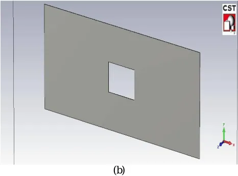
Figure 3 (a) Front view of proposed designed microstrip stepped impedance butterworth function LPF.
One rectangular shaped slot of equal size is introduced in the both capacitor part (C2 & C4) of the proposed design of
microstrip Butterworth low pass filter. Dimension of rectangular shaped slots is 0.7mm X 6mm and it is placed form the 0.4mm far away from the inductor part (L1 & L5) of the design.
IV.SIMULATIONRESULTS
The simulated results of the stepped impedance Butterworth Low Pass Filter for WLAN application is shown in the figure 4. The graph obtains after the simulation in CST Software [11].
Figure 4The simulated results of the stepped impedance Butterworth Low Pass Filter for WLAN application
From the response shown in figure 4, it is clear that the cut-off frequency is found to be 5GHz for stepped-impedance low pass filter. Hence stepped impedance low pass filter is capable of passing the frequency less than 5GHz & reject the frequency after 5GHz.
Figure6The angular plot of the result of the stepped impedance Butterworth Low Pass Filter for WLAN application
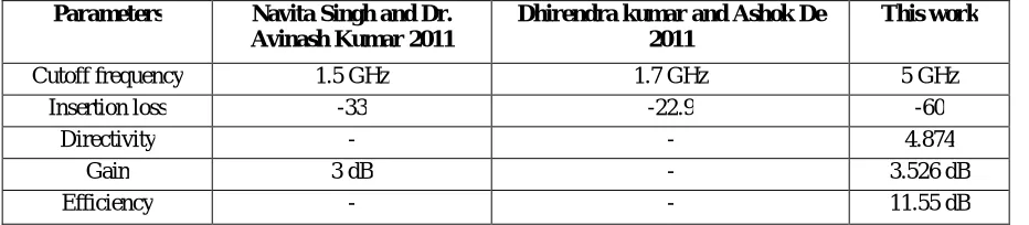
Table 2. Comparison of Butterworth filter parameters
V. CONCLUSION
The proposed design was implemented and analyzed at the centre frequency 5GHz. A sharp rate of cutoff with reduce label of sideband fluctuation of the response achieved by introducing the slots in the ground plane structure which is behave as defected and two equal slots of rectangular shaped in the structure of low pass filter I have made slots in the ground structure produces so that the low power will consumption takes places and use the dielectric FR4 0.038mm and make the circuit as an ideal and passes the most of the signal at the desires frequency and the graphical structure is maximally flat and the try to make the minimum insertion loss -60dB which is very less loss and the efficiency is
Parameters Navita Singh and Dr. Avinash Kumar 2011
Dhirendra kumar and Ashok De 2011
This work
Cutoff frequency 1.5 GHz 1.7 GHz 5 GHz Insertion loss -33 -22.9 -60
Directivity - - 4.874
Gain 3 dB - 3.526 dB
[3] A. Casanueva, A. León, O. González, and A. Mediavilla, “A compact microstrip step-impedance low-passfilter (SILPF) using complementary split ringresonators” IEEE MTT-S International Microwave Workshop on Wireless Sensing, Local Positioning, and RFID (2009 - Croatia).
[4] Anju and Mamta Katiyar, “Design of Butterworth and Chebyshev 1 Low pass Filter for Equalized Group Delay,” International Journal of
Advanced Research in Computer Science and Software Engineering, ,May 2012.
[5] D. Kumar, A. De, “Effective Size Reduction Technique for Microstrip Filters”, Journal of Electromagnetic Analysis and Applications, 2013.
[6] Garvansh, Abhay Singh Kushwaha, Navita Singh, Arun Kumar,“Implementation of Stepped Impedance Low PassMicrostrip Line Filter for
Wireless Communication”International Journal of Advanced Research in Computer and Communication Engineering July 2014.
[7] Pozar, David M. “Microwave Engineering” 2nd Edition, USA: John Wiley &Sons/ D. M. Pozar, “Microwave engineering newyork,” John Wile
YandSons,Third Edition.
[8] Jia-Sheng Hong, M. J. Lancaste “Microstrip filters for RF / Microwave Application” A Wiley-IntersciencePublivation book.
[9] Weng, L. H., Y. C. Gue, X. W. Shi, and X. Q. Chen, “An overview on defected ground structure,” Progress In Electromagnetics Research B,
2008
[10] Atallah Balalem, Ali,Jan Machac “Quasi-Elliptic Microstrip Low-Pass Filters Using an Inter digital DGS”IEEE Microwave and Wireless
Components letters 2007.
[11] CST (computer Simulation Technology) microwave software studio 2010
[12] Abraham Ortega,at.al.” Design of Low-Pass Microstrip Filters Based on Defected Ground Structure” ©2011 IEEE
[13] G. M. Raffiquzzaman and at.al.”A new approach to design Microstrip lowpass filter using novel defected ground structure” Dec 2014. [14] Navita Singh, at.al., “ Low Pass Filter For L-Band Application Using Stepped-Impedance Microstrip Lines” JERS APRIL-JUNE,2011. [15] Dhirendra Kumar and Ashok De,” Compact Low Pass Filter Design for L-Band Application”, JournalL-Band Application”
Journal of Electromagnetic Analysis and Applications 2011.
[16] Chul-Soo Kim, Juno Kim, at.al., ” A Design of the Low-Pass Filter Using the Novel Microstrip Defected Ground Structure”, IEEE transactions on microwave theory and techniques, 2001
[17] Lung-Hwa Hsieh and Kai Chang,” Compact Elliptic-Function Low-Pass Filters UsingMicrostrip Steppe Impedance Hairpin Resonators”, IEEE
transactions on microwave theory and techniques 2003

![figure 4. The graph obtains after the simulation in CST Software [11].](https://thumb-us.123doks.com/thumbv2/123dok_us/7772066.1280133/5.595.64.538.290.447/figure-graph-obtains-simulation-cst-software.webp)