Comparison Study of Different Methods of on
Load Tap Changer
Rolga Roy
1, Aswani Suseelan
2,
Anugraha P
3Assistant Professor, Dept of EEE, Sree Buddha College of Engineering for Women, Elavmthitta, Kerala, India 1
UG Student, Dept of EEE, Sree Buddha College of Engineering for Women, Elavmthitta, Kerala, India 2
UG Student, Dept of EEE, Sree Buddha College of Engineering for Women, Elavmthitta, Kerala, India3
ABSTRACT: Voltage control is an essential part of the electric energy transmission and distribution system to maintain proper voltage limit at the consumer’s terminal. Different methods On Load Tap Changers areRemote Control System, Solid-State On Load Tap-Changer using Microcontroller and Supervisory Control and Data Acquisition (SCADA). Remote Control System for Transformers with On-Load Tap Changer has been designed to be implemented in Remote Telecontrol Units (RTU) located in Transformation Centers (CT) with on-load tap changing capability. The control strategy of solid-state on load tap-changer is Microcontroller-based, ensuring flexibility in programming the control algorithms. SCADA encompasses the collecting of the information, transferring it back to the central site carrying out any necessary analysis and control and then displaying that information on a number of operator screens or displays.
KEYWORDS: On-Load Tap Changer, Voltage Regulator, Microcontroller Applications, Power System Control, Voltage Control, Power Transformers, Tap Changer, Remote Control, SCADA,RTU, CT and RCS..
I.INTRODUCTION
To meet the increased demands on the power system two or more transformers are connected in parallel. Voltage fluctuations pose a serious problem during parallel operation of transformers. Besides the generating units that provide the basic voltage control, there are many additional voltage-controlling agents e.g., shunt capacitors, shunt reactors, static VAR compensators, regulating transformers. Also, taking care of security and economic reasons, network operation demands suitable management of available resources. So, electrical utilities are forced to carry out an effective control of power flow (active and reactive) derived by the different circuits that compose the power system. It is essential to control and regulate the system voltage in those network bus bars that, due to their importance or location, allow guaranteeing: Maintenance of voltage and frequency within the established limits, Power supply continuity, Control of power flows according to operation needs. There are different existing devices to achieve this goal. But transformers, with on-load tap changing capability, are quite commonly applied to regulated bus voltage for a long time[1]. The most popular one, among all those agents for controlling voltage levels at the distribution and transmission system, is the on-load tap changer transformer. It serves two functions-energy transformation in different voltage levels and the voltage control. The on-load tap changing (OLTC) regulators have been widely used since the introduction of electrical energy[7]. They ensure a good regulation of the output voltage in presence of large variations of the input voltage with typical response time from several milli-seconds to several seconds. Earlier mechanical type of on load tap changers were into practice. But they had considerable limitations and drawbacks like arcing, high maintenance, service costs and slow reaction times[2].
The continuous growth of power semiconductor devices, such as the insulated gate bipolar transistor (IGBT), triac, thyristor, has allowed the development of quick operating OLTC regulators which is also helpful in fixing other problems in theac mains, like flicker and sags[1]. The major idea in the Solid-state-assisted tap changer is that solid-state switches with more controllability, operates during the tap-changing process instead of mechanical switches which helps in reducing the arcing phenomena during the tap-changing process. The control strategy is Microcontroller-based, ensuring flexibility in programming the control algorithms.
II. LITERATURE SURVEY
One of the main concerns of electrical utilities is the power quality. Customers demand uninterrupted supply with minimum disruption. In this sense, voltage stability and security assessment implies network loading and voltage control evaluation. Also, taking care of security and economic reasons, network operation demands suitable management of available resources. So, electrical utilities are forced to carry out an effective control of power flow (active and reactive) derived by the different circuits that compose the power system. In this way, it is essential to control and regulate the system voltage in those network bus bars that, due to their importance or location, allow to guarantee:
- Maintenance of voltage and frequency within the established limits.
- Power supply continuity.
- Control of power flows according to operation needs.
There are different existing devices to achieve this goal. But transformers, with on-load tap changing capability, are quite commonly applied to regulated bus voltage for a long time. So, over last years, several researchers have analyzed the dynamic operation of on-load tap changers (LTC). These investigations try to obtain a model that simulates their behavior with enough precision. Also, they have tried to develop control algorithms, methods and techniques to make possible the use of transformers with LTC in an automated, efficient and safe way.
III. REMOTE CONTROL SYSTEM
The Transformation Centers where this Remote Control System (RCS) can be implemented are totally automated and all operations are remotely controlled, except those corresponding to local automatisms. For this reason, they do not require the permanent presence of personnel and their actions are reduced to preventive and corrective maintenance operations. The remotes are telecontrolled from the corresponding Remote Operation Control Position through a RS-232 series communication, whose physical connection (series interface + communication modem) is duplicated for security reasons. In this way, using a mechanism that supervises the connection and its automatic commutation, communication is guaranteed after a failure, in some of its components, happens. Also, it is possible to maintain the security standards that are required, nowadays, for this type of installations[1].
A. HV/MV Transformers
In this case, the object of LTCC function is to reduce the voltage level, to decrease the load in the network when emergency situations happen. Within HV/MV transformers, autonomous transformers and non autonomous ones can be distinguished.
Autonomous transformers. In this case, there is an external regulator that directly receives the position set point from the ROCP. This regulator takes the commutator to the wished tap position. Therefore, the remote does not need any LTCC function for this type of transformers.
Non autonomous transformers. In this case, there is an external regulator to take the transformer to prefixed
tap position. The aim of LTCC function is to decrease the voltage until a reduced level. This level is fixed by the tap position set point that arrives from the ROCP when the automatism is activated.
B. HV/HV Transformers
As some HV/HV transformers have the possibility of working connected in parallel, the operation of these units is specified from the ROCP by means of a modifiable parameter. So, two transformers connected to the same bus bar can work individually or in parallel according to the operation requirements. In the case of independent transformers (not prepared to work in parallel), the previous parameter will be always in on the “individual” setting and it will not be modifiable. Within this type of transformers, it can distinguish between:
Independent transformers. “Individual/Parallel” parameter, that fixes the operation of the transformer, is not
modifiable and will be always on “Individual” position. The automatism supervises the fulfillment of all operation commands. In case of detecting some failure by unsuccessful command, the process is interrupted, LTCC function is deactivated and corresponding failure signal is generated.
Transformers connectable in parallel. In this case, “Individual/Parallel” parameter will be modifiable by the
operator from the ROCP.
There is only one signal for both transformers susceptible to work in parallel. So, each pair of LTCC functions will work in parallel or individual way according to the value of this common parameter. Finally, it can be highlighted that this automatism has been implemented in already existing remote units. Therefore, these remote units develop many other functions, mainly those regarding to telecontrol. Thus, the RCS for transformers with LTC has been integrated in RTUs as a semi-independent module, which interchanges signals and information with the process by means of input/output cards and with the ROCP via series communication card. The developed automatism has been designed as a modular system. So, it can be applied to different Transformation Centres configurations by adjusting its particular characteristic parameters. If necessary, it also allows including more advanced remote supervision and control functions. The Remote Control System for Transformers with On-Load Tap Changer presented in this communication is able to control a maximum of eight transformers.
IV. SOLID-STATE ON LOAD TAP-CHANGER USING MICROCONTROLLER
With the use of high power semiconductor devices such as triac, IGBTs, Thyristor, problems related with the mechanical on-load tap changing power transformer have been eliminated. In order to overcome these limitations and drawbacks, new circuits and configurations for tap-changers have been introduced. These may be classified into two groups.
Electronically assisted (or hybrid) on-load and
Fully electronic (or solid-state) tap-changers
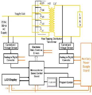
A common OLTC regulator scheme is shown in Fig.1. The prototype semiconductor tap changer consists of a thyristor as the switching device to turn on the selected tap of the power transformer. As displayed in figure 1, the low voltage circuit is separated from the high voltage circuit in order to protect the microcontroller from damage. Furthermore this step-down transformer helps in bringing down the transformer’s output voltage to an appropriate value for microcontroller operation. This reduced voltage is then compared with reference voltage before fed into the triggering circuit. The output of the microcontroller is also connected to an isolator. There is a 115/12 V step-down transformer, peak detector, filter and pulse transformer forming a feedback loop circuit. The function of this feedback loop is to convert the 110 V AC line voltage at secondary of the tap changing transformer to an acceptable DC level voltage for the microcontroller. Peak detector will detect the peak value of the feedback signal and gives a constant equivalent voltage. While the pulse transformer acts as an electrical isolator to the input of microcontroller.89s52 microcontroller is used as the logical central process control to process the input signal and produce a suitable output signal according to the program loaded into the microprocessor. The microcontroller acts as a trigger by injecting pulses to the selected thyristor pair representing the appropriate taps. At any instant, only one pair of thyristor will be in its ON state while others are turned OFF.
Fig. 1. OLTC power and control scheme
V.SUPERVISORY CONTROL AND DATA ACQUISITION
SCADA is the acronym for Supervisory control and Data Acquisition. SCADA refers to the combination of telemetry and data acquisition. . SVADA encompasses the collecting of the information, transferring it back to the central site carrying out any necessary analysis and control and then displaying that information on a number of operator screens or displays. A SCADA System consists of a number of Remote Terminal Units (or RTUs) collecting filed data and sending that data back to a master station van a communication system. The master station displays the acquired data and also allows the operator to perform remote control tasks. SCADA software can be divided into two types. Proprietary or open companies develop proprietary software to communicate to their hardware. These systems are sold as “turn-key” solutions. Often in SCADA systems the RTU (Remote Terminal Unit) is located at a remote location. This distance can vary from tens of meters to thousands of Kilometres. One of the most cost-effective ways \of communicating with the RTU over long distances can be by dialup telephone connection. With this system the devices needed are a PC, two dialup modems and the RTU (assuming that the RTU has a built in COM part.) The modems are put in the auto-answer mode and the RTU can dial into the PC or the PC can dial the RTU.The software to do this is readily available from RTU manufacturer’s line Modems are used to connect RTUs to a network over a pair of wires. These systems are usually fairly short (Up to 1 Kilometre) and use FSK (frequency Shift keying) to communicate.The Sensor to Panel type of SCADA system has the following advantages: It is simple, no CPUs, RAM, ROM or software programming needed, The sensors are connected directly to the meters, switches and lights on the panel, It could be (in most circumstances) easy and cheap to add a simple device like a switch or indicator[3].Then advantages of the PLC / DCS SCADA system are: The computer can record and store a very large amount of data, the data can be displayed in any way the user requires, thousands of sensors over a wide area can be connected to the system, the operator can incorporate real data simulations into the system, many types of data can be collected from the RTUs and the data can be viewed from anywhere, not just on site.
Interference and noise are important factors to consider when designing and installing a data communication system with particular considerations required to avoid electrical interference. Noise can be defined as the random generated undesired signal that corrupts (or interferes with) the original (or desired) signal. This noise can get into the cable or wire in many ways. It is up to the designer to develop a system that will have a minimum of noise from the beginning. Because SCADA systems typically use small voltage they are inherently susceptible to noise. The use of twisted pair shielded Cat5 wire is a requirement on most systems. Using good wire coupled with correct installation techniques ensures the system will be as noise free as possible. Fibre Optic cable is gaining popularity because of its noise immunity. At the moment most installations use glass fibres, but in some industrial areas plastic fibres will be increasingly used[6].
Future data communications will be divided up between Radio, Fibre Optic and some Infrared systems. Wire will be relegated to supplying power. And as power requirements of electronics become minimal, even the need for power will bereduced.Local Area Networks (LAN) are all about sharing information and resources. To enable all the nodes on the SCADA network to share information, they must be connected by some transmission medium. The method of connection is known as the network topology. Nodes need to share this transmission medium in such a way as to allow all nodes access to the medium without disrupting an established sender. A LAN is a communications path between computers, file-servers, terminals, workstations and various other intelligent peripheral equipment, which are generally referred to as Devices or Hosts. A LAN allows access to devices to be shared by several users, with full connectivity between all stations on the network. A LAN is usually owned and administered by a private owner and is located within a localised group of buildings.Ethernet is the most widely use LAN today because it is cheap and easy to use. Connection of the SCADA network to the LAN allows anyone within the company with the right software and permission, to access the system. Since the data is held in a database the user can be limited to reading the information. Security issues are obviously a concern, but can be addressed[6].
VI. CONCLUSION
Load Tap-Changer using Microcontroller the system stability is improved, because of quick response. Because of static devices, maintenance cost is reduced due to elimination of frequent sparking. Output voltage can be regulated in the range of ±5 V of nominal voltage. SCADA control has more advantages than Remote Control System and Solid-State On Load Tap-Changer using Microcontroller. Any number of substations can be controlled by a single SCADA centre. SCADA is preferred more today due to its advantages. It can store a very large amount of data and data can be displayed in any way the user requires. Data can be viewed from anywhere not just on site. Thousands of sensors over a wide area can be connected. The operator can incorporate real data simulations into the system.
REFERENCES
[1] K.J. Sagastabeitia, Z. Aginako, A.J. Mazónand I. Zamora.,“ Remote Control System for Transformers with On-Load Tap Changer”. [2] Nikunj R. Patel, Makrand M. Lokhande, Jitendra G., and Jamnani”Solid-State On Load Tap-Changer for Transformer Using
Microcontroller”ISSN: 2321-9939.
[3] VahidaBahaa Hassan, Nabil Litayem., and Mohyi el-din Azzam., “Recent Trends in SCADA and Power Factor Compensation on Low Voltage Power Systems for Advanced Smart Grid”,International Journal of Recent Development in Engineering and Technology” , Volume 3, Issue 1, July 2014.
[4] H F Wang., “Multi-agent co-ordination for the secondary voltage control in power-system contingencies”. IEE Proc., General Transmission and Distribution, Vol. 148, No.1, pp.61-66,January 2001.
[5] J.H. Choi and L.C. Kim., “The Online Voltage Control of ULTC Transformer for Distribution Voltage Regulation”, International Journal of Electrical Power and Energy Systems, Vol. 23, No. 2, pp.91-98, February 2001.
[6] B. Kasztenny, E. Rosolowski, J. Izykowski, M. M. Saha, and B. Hillstrom.,”Fuzzy Logic Controller for On-Load Transformer Tap Changer”, IEEE Trans. Power Del., vol. 13, no. 1, pp. 164–170, Jan. 1998.