ISSN (Print) : 2320 – 3765 ISSN (Online): 2278 – 8875
I
nternational
J
ournal of
A
dvanced
R
esearch in
E
lectrical,
E
lectronics and
I
nstrumentation
E
ngineering
(An ISO 3297: 2007 Certified Organization)
Vol. 4, Issue 3, March 2015
Design and Implementation of Smart Lock for
Vehicles
P Parthiban
1, V Arunkumar
2, M Anishjebasingh
3, K Hariprasath
4, K Saravanan
5Assistant Professor, Department of Electronics and Communication, New Prince Shri Bhavani College of Engineering
and Technology, Chennai, India1
Student, Department of Electronics and Communication, New Prince Shri Bhavani College of Engineering and
Technology, Chennai, India2, 3, 4, 5
ABSTRACT: This proposed system is to attempt a design for the vehicle theft avoidance using the GPS and GSM.
This system alert the owner of thevehicle by the SMS through the GSM .The system is also to control the vehicles engine by the SMS from the owner. The use of the GPS and GSM modules along with the Microcontroller that is installed in the vehicle is to control and to track the vehicle. This system also eliminates the false buzzer alarm. The purpose of this system during theft is, a) It alert the owner ; b) enables the buzzer alarm by the owner still he reach the vehicle parked area ; c) The two wheelers are possible to lift by the thief so the GPS-GSM MODEM is help to track the two wheeler by the latitudes and longitude values. Once this proposed system is installed in the vehicle it is not possible to undergo for any theft.
KEYWORDS: Microcontroller, GPS module, GSM module and proximity sensor.
I. INTRODUCTION
In this modern world, day by day the numbers of vehicle users are increased and also beside the number of vehicle theft are also increased. This makes the vehicle owner to worry a lot about their vehicle. So, in this paper the communication is established between the vehicle owner and their vehicle[1] . Thus the vehicle owner can know the status of vehicle through their mobile phone whenever he/she want. So he/she can easily find and control whenever their vehicle is ill-legally accessed by any other person who trying to theft the vehicle of others. Modernautomotive engineering, Here we incorporating elements of mechanical, electrical, electronic, software and safety engineering as applied to the design, manufacture and operation of motorcycles, automobiles, buses and trucks[2][3][4]. Nowadays we have to implement a modern technology throughout the automobiles every day. Among those advanced feature is preventing the vehicle theft by the unknown person. In this paper we prescribe a simple cost effective technique of preventing vehicle theft using GSM and GPS[5][6].The proximity sensor is ON by the owner of the vehicle through mobile phone(SMS) when the vehicle get parked by the owner. The GSM modem in this paper is to control and to know the status of the vehicle by the owner. The GPS modem is only for the vehicles which can lift able to know the location of the vehicle if it is theft by some other unauthorized person[7][8]. The tilt alarm is provided to make a buzzer sound, only during the theft is carried out by the owner of the vehicle. TheMicrocontroller is in this project is to interface these GSM modem, GPS modem, proximity sensor together by using the Embedded C language. The Embedded C language is to deployment the interfaced components in the correct manner. This program is flash to the Microcontroller by using MPLABIDE v8.56 software.
II. HARDWARE
ISSN (Print) : 2320 – 3765 ISSN (Online): 2278 – 8875
I
nternational
J
ournal of
A
dvanced
R
esearch in
E
lectrical,
E
lectronics and
I
nstrumentation
E
ngineering
(An ISO 3297: 2007 Certified Organization)
Vol. 4, Issue 3, March 2015
Fig.1: Block diagram of theft avoidance and tracking system.
How longer it has been there. The basic function in vehicle unit is to acquire, if sensor is interpreted by the some other person which is interpreted only during the theft because the sensor is placed in the lock. Microcontroller unit form the heart of this system unit which acquires and process the position data from the GPS module and also to control the status of the vehicle. If the two wheeler is lift by the thief then the GPS receiver in the system receives and resolves then
avigation message broad casted by GPS position from
thesatellites,computesthelongitudeandlatitudeofvehiclecoordinates,transformsit into the GSM message form by GSM communication controller, and sends the message to monitoring center via the GSM network at final it reaches the user.
Proximity sensor
The proximity sensor is placed near the lock of the vehicle which is connected to A/D port in the microcontroller. The proximity sensor has transmitter and receiver which producea short range EM waves. When this short range EM waves is interpreted by any object the receiver in this sensor does some changes in the output and the output is connected to the microcontroller. This sensor able to sense the near by objects. Proximity sensor as shown in fig. 2.
Fig. 2 : proximity sensor
ISSN (Print) : 2320 – 3765 ISSN (Online): 2278 – 8875
I
nternational
J
ournal of
A
dvanced
R
esearch in
E
lectrical,
E
lectronics and
I
nstrumentation
E
ngineering
(An ISO 3297: 2007 Certified Organization)
Vol. 4, Issue 3, March 2015
The data communication in this system lies in Wireless communication control terminals that uses GSM Modules to transfer long-distance data extensively and reliably. This GSM module is serial communication with the PIC18F45J11 microcontroller. This GSM module Transmitter (TX) and Receiver(RX) is connected to the UART port in the microcontroller. This GSM module is able to connect with another GSM module because it is the cellular network.
Fig.3 :GSM MODEM
Here the system uses the 2G network for the data communication so it is operating in the 900MHZ and 1800MHZ bands.It also able to work with the 3G network is operating in the 2100MHZ band. Any type of network SIM can be used in the GSM module. The microcontroller deploy the GSM module to create the SMSwhen the proximity sensor is get interpreted and the SMS sent to the owner mobile by the use of the mobile network. This SMS reaches the owner and alert them that someone is un authourisedly accessing the vehicle. This transmission and reception done by network of the SIM which is placed inside GSM modem. GSM modem as showninFig.3.
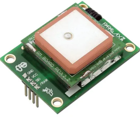
GPS module
The Global Positioning System is given the values of latitude and longitude of the system where it is installed. These values are getting from the satellite from the earth orbit.
Fig.4: GPS module
In this project the high sensitivity GPS module is used. This is sufficient to track the vehicle even the vehicle is hide in any place is tracked and the location is also more accurate. This GPS module is used only when the vehicle is lift by the thief. The GPS module is shown in the fig. 4.
ISSN (Print) : 2320 – 3765 ISSN (Online): 2278 – 8875
I
nternational
J
ournal of
A
dvanced
R
esearch in
E
lectrical,
E
lectronics and
I
nstrumentation
E
ngineering
(An ISO 3297: 2007 Certified Organization)
Vol. 4, Issue 3, March 2015
This system uses the PIC18F46J11 microcontroller which having 44pins. This is a 8-Bit microcontroller it has high stack memory so more number of interrupt (sub-operations) is possible. The power supply required to operate is 3.3V DC. The operating frequency is 4MHZ but by the program which is flash into the microcontroller multiplies the operating frequency into 16MHZ so the execution speed of the operation is increased. The registers in the microcontroller is accessed by the 8-bit address.
This microcontroller has 32 I/O ports. These 32 I/O ports are divided into port A,port B, port C,port D,port E and each having the pins 5, 8,8,8,3. The sensors are connected to the ADC ports. This ADC port has 3 pins in the microcontroller. The data is transferred to the external device through serial to parallel interface (SPI) which having 3pins this port requires the synchronization. The UART port is to interface with the GPS and the GSM modem. The UART port has one TX and one RX pin but in this system there are two UART is used. The easy handling and flexibility make PIC applicable to this system. PIC18 series microcontroller is shown in fig.5.
Fig. 5 : microcontroller
III. SMART LOCK SYSTEM FUNCTION
In normal routine, the owner of the vehicle starts his/her vehicle by inserting the key and makes a drive. But after the drive they park their vehicle in some place. This thing allows a chance for theft of the vehicle by some other. After the vehicle gets parked, the proximity sensor is switched ON and the engine of the vehicle is under the control of owner of the vehicle.
If some other person is trying to access the others vehicle by inserting the duplicate keys or by any other way, the proximity sensor near the key pattern is get interpreted and sent an SMS to the owner of the vehicle to alert, that some is access your vehicle through the GSM modem. After the owner get the alert SMS, he\she enables the tilt alarm (buzzer sound) by sending a simple SMS to scare that person who is accessing the vehicle unauthourisedly.
ISSN (Print) : 2320 – 3765 ISSN (Online): 2278 – 8875
I
nternational
J
ournal of
A
dvanced
R
esearch in
E
lectrical,
E
lectronics and
I
nstrumentation
E
ngineering
(An ISO 3297: 2007 Certified Organization)
Vol. 4, Issue 3, March 2015
Suppose if the vehicle lifted by the thief it can be easily tracked by the latitude and longitude values provided by the GPS modem. The GPS values are given as the input to the microcontroller These values got by the owner of the vehicle through the mobile phone (SMS) by the GSM modem.
Fig.6 : flowchart of the system
IV. ALGORITHM
Step1: Start the program
Step2: Check whether the sensor value is 0.if YES, Go to step 3, else go to step 4.
Step3: Engine starts when the key is inserted
Step4: Engine will be in the control of the owner
Step5: If sensor interrupted then it alerts the owner, about the illegal access of the vehicle
Step6: Owner has the control over the buzzer to frighten the thief. And it compares the GPS value with the previous
value.
step7: IF the GPS value is same then it stops the program
step8: Else it gets continuous GPS value to track the vehicle.
V. CONCLUSION
ISSN (Print) : 2320 – 3765 ISSN (Online): 2278 – 8875
I
nternational
J
ournal of
A
dvanced
R
esearch in
E
lectrical,
E
lectronics and
I
nstrumentation
E
ngineering
(An ISO 3297: 2007 Certified Organization)
Vol. 4, Issue 3, March 2015
REFERENCES
[1]Elia Nadira Sabudin, Siti Zarina Mohd Muji, Mohd. Helmy Abd Wahab, Ayob Johari, Norazman Bin Ghani,“GSM-based Notification Speed Detection for Monitoring Purposes”, IEEE, Department of Computer Engineering, University Tun Hussein Onn Malaysia in 2011.
[2]M. AL-Rousan, A. R. AI-Ali and K. Darwish “GSM-Based Mobile TeleMonitoring and Management System for Inter-Cities Public Transportations”, International Conference on Industrial Technology (ICIT), Computer Engineering Dept., American University of Sharjah, UAE in
2014, pages 859-862.
[3]Stephen Teang Soo Thong, Chua Tien Han and Tharek Abdul Rahman “Intelligent Fleet Management System with Concurrent GPS & GSM RealTime Positioning Technology”, IEEE ,Wireless Communication Centre (WCC), universiti Teknologi Malaysia (UTM), Malaysia in 2011. [4] Hui Hu, Lian Fang “Design of Vehicle Monitoring System Based on GPS/GSM/GIS” Third International Symposium on Intelligent Information Technology Application ,School of Information Engineering, East China Jiao Tong University, Nanchang, Jiangxi, China in 2010. Pages 278-279. [5] Umar Farooq, Tanveer ul Haq, Muhammad Amar, Muhammad Usman Asad, Asim Iqbal “GPS-GSM Integration for Enhancing Public Transportation Management Services” Second International Conference on Computer Engineering and Applications, Department of Electrical
Engineering University of The Punjab Lahore-54590, in 2013.
[6] T.Shyam Ramanath, A.Sudharsan, U.Pelix Udhayaraj, “Drunken Driving and Rash Driving Prevention System”, International Conference on Mechanical and Electrical Technology (ICMET 2013), Sri Sai Ram Engineering College, Chennai, India in 2013, page 603.
[7] Thuong Le-Tien, Vu Phung-The “Routing and Tracking System for Mobile Vehicles in Large Area”, Fifth IEEE International Symposium on
Electronic Design, Test & Applications Dept. of Electrical Electronics Engineering, HCM University of Technology, Vietnam in 2012.