ISSN (Print) : 2320 – 3765 ISSN (Online): 2278 – 8875
I
nternational
J
ournal of
A
dvanced
R
esearch in
E
lectrical,
E
lectronics and
I
nstrumentation
E
ngineering
(A High Impact Factor, Monthly, Peer Reviewed Journal)
Website: www.ijareeie.com Vol. 8, Issue 10, October 2019
The Analysis of Battery Management System
for Electric Vehicle with DC-DC Converter
S.Logitha
1, Dr.K.Umapathi
2, K. Parimala
3PG Scholar, Dept. of EEE, Jansons Institute of Technology, Coimbatore, Tamilnadu, India 1 Associative Professor, Dept. of EEE, Jansons Institute of Technology, Coimbatore, Tamilnadu, India 2
Assistant Professor, Dept. of EEE, Jansons Institute of Technology, Coimbatore, Tamilnadu, India 3
ABSTRACT: In recent trends, the electric vehicle is an important need in our country, by implementing electric vehicles fuel consumption and atmospheric pollution get reduce. Designing such an efficient and effective electric vehicle, a proficient energy storage system is required. The purpose of this project is to design an active cell balancing using a converter for series-connected lithium-ion cells. This project presents a methodology that allows the development of converter based cell balancing to charging series-connected cells in lithium-ion batteries equally, which helps to enhance the lifetime and capacity of the battery. The converter chosen here is a buck converter. Lithium-ion batteries are used for electric vehicles to obtain high efficiency by the store the energy obtains from renewable energy resources. Lithium-ion cells are intolerant to overcharge and over-discharge, where overcharged cell causes explosion and over-discharged cell reduce the life cycle of the battery. The performance of the proposed system is analyzed through simulation, where Matrix laboratory (MATLAB) software is used for simulation and results are obtained.
KEYWORDS: BMS, DC-DC Converter, Cell balancing system, series-connected cell
I.INTRODUCTION
The Government of India set an aggressive objective of 6-7 million electric vehicles (EVs) before the finish of 2020 under the National Electric Mobility Mission (NEMM) Plan2013. This is an exertion towards guaranteeing EV producing initiative and national fuel security. The world is making progress towards perfect and effective types of energy because of different elements like – increment in worldwide energy request, constrained petroleum product assets and an Earth-wide temperature boost. The commercialization has advanced through versatile batteries for PCs, cell phones, working instruments to half and half electric vehicles, module crossovers and completely electric vehicles. Effective appropriation of EVs will require high-execution batteries (high energy and control thickness with long cycle life) and an advanced Battery Management System (BMS). BMS is an electronic framework that protects a battery from over-charging/over-discharging and guarantees the sheltered activity of EVs. In the setting of a quickly developing EV showcase in India, it is essential to build up an exhaustive and develop BMS program. Mindfulness about BMS activity will enable smooth EV reception and safe driving conditions. Further, for the in degeneration of EV producing in India, it is significant for partners and shoppers to think about worldwide BMS providers.
ISSN (Print) : 2320 – 3765 ISSN (Online): 2278 – 8875
I
nternational
J
ournal of
A
dvanced
R
esearch in
E
lectrical,
E
lectronics and
I
nstrumentation
E
ngineering
(A High Impact Factor, Monthly, Peer Reviewed Journal)
Website: www.ijareeie.com Vol. 8, Issue 10, October 2019
II. BATTERY CELL BALANCING TOPOLOGY
There are two types of balancing methods, it can be either passive or active, and they are named as passive balancing method and active balancing method. In Passive balancing, the method can be applied only for Lead-acid and Nickel-based batteries. Lead-acid and Nickel-based batteries can be fetched into overcharge conditions without permanent cell damage. The excess energy is released through increased cell body temperature when the overcharge is not very severe. When the overcharge is too much, the energy will be released by gassing via the gassing valve equipped on the cells. It is the natural method of balancing a series string of such cells. The balancing problems grow exponentially with the number of series cells, therefore, overcharge balancing is only effective on a small number of series cells. However, this method is a cost-effective solution for low voltage Lead-acid and Nickel-based battery systems.
The active cell adjusting techniques expel charge from higher vitality cell(s) and convey it to bring down vitality cell(s). Various topologies are utilized by the active component utilized for putting away the energy, for example, capacitor and additionally inductive segment just as controlling switches or converters. active cell adjusting is a progressively perplexing adjusting procedure that redistributes charge between battery cells during the charge and release cycles, in this way expanding framework show time to expanding the complete useable charge in the battery stack, diminishing accuse time looked at of inactive adjusting, and diminishing heat produced while adjusting.
III. SELECTION OF CONVERTER
The issues in the battery management system were overcome with some cell balancing topology based on the converters. However proposed techniques have a shortcoming like improper monitoring and cell balancing, cost, efficiency, and high voltage stress level respectively. The buck-boost and Cuk converter combined to form a battery cell equalizing circuit, but it has the large capacitor which results in large charging and discharging current. Therefore, this type of circuit needs high current tolerance switches and the capacitor cost is high [3-5]. The bidirectional Cuk converter can be used for cell balancing but it takes a long time for cell equalization and the voltage stress is high is the main drawbacks of this system. Its fundamental detriments are the high info voltage wave and high electrical weights on the switch and the diode. The dissipative balancing circuit using shunt resistors has a simple structure and control [6-7]. But its low efficiency and the need for heat management are the disadvantages of the method [8]. The bi-directional flyback converters can be used for voltage equalization in battery but it consists number of switches it may increase the switching losses and efficiency get reduced [9],the flyback converter with transformer along with a lossless snubber is an attractive choice for cell equalization topology in battery but it can be used for low power applications as they can be built with low cost and excellent efficiency[10]. Compare with another non-isolated dc-dc converter the performance of buck converter is good; its efficiency is higher than other converters [11]. The balancing of cell in battery with buck converter has the low voltage stresses and current stress o, the equalization speed is high, its cost is low and easy to implement when compared to fly-back converter based cell balancing methodology [12-13].
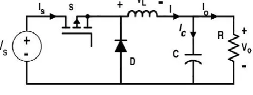
Fig 1: Circuit diagram of the buck converter
ISSN (Print) : 2320 – 3765 ISSN (Online): 2278 – 8875
I
nternational
J
ournal of
A
dvanced
R
esearch in
E
lectrical,
E
lectronics and
I
nstrumentation
E
ngineering
(A High Impact Factor, Monthly, Peer Reviewed Journal)
Website: www.ijareeie.com Vol. 8, Issue 10, October 2019
current. This voltage drop balances the voltage of the source and in this manner decreases the net voltage over the load. After some time, the speed of progress of current diminishes, and the voltage over the inductor additionally then diminishes, expanding the voltage at the load. During this time, the inductor stores energy as an attractive field the switch is opened while the current is as yet fluctuating, and afterward, there will consistently be a voltage drop over the inductor, so the net voltage at the load will lower than the input voltage source. During the off-condition, the inductor is releasing its discharging energy into the rest of the circuit. The circuit diagram of the buck converter is shown in fig1.
IV. CONVENTIONAL SYSTEM
The performance of the battery is affected by numerous factors. Among the several factors, cell balancing is the most significant factor. Without cell balancing where the performance of the battery cell reduced by voltage difference among the individual. Inequality of cell voltage in battery systems is very usual due to various causes ofCell imbalance. In the conventional system, the current controlled based charging and discharging of battery cells have been done. In the existing system individual cell balancing and individual cell voltage monitoring are not done. All the cells in the battery get charged unrelated to the preliminary SOC of the individual cell, and all the cells get charged and discharged randomly. Due to the cells get charged and discharged rapidly the output efficiency of the battery become less. The proper monitoring and control of charging and discharging of the battery cell are not done in the existing system; therefore the lifetime and capacity of the battery get reduced.
Fig 2: Block diagram of a conventional system
The DC source obtained from the solar panel is given to the buck converter. The buck converter is DC-DC converters which step down the input voltage. The input voltage is given the buck converter, buck converter step down the input voltage and charge the battery cells randomly. The block diagram of a conventional system is shown in fig2.
Fig 3: Circuit diagram of the conventional system
BUCK converter
ISSN (Print) : 2320 – 3765 ISSN (Online): 2278 – 8875
I
nternational
J
ournal of
A
dvanced
R
esearch in
E
lectrical,
E
lectronics and
I
nstrumentation
E
ngineering
(A High Impact Factor, Monthly, Peer Reviewed Journal)
Website: www.ijareeie.com Vol. 8, Issue 10, October 2019
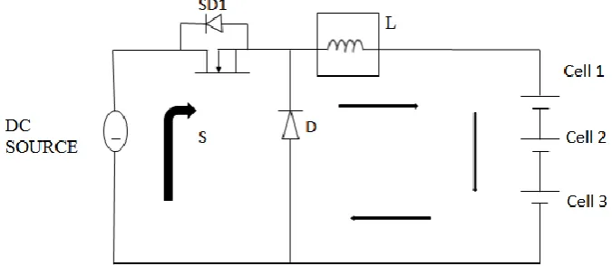
The circuit diagram of a conventional buck converter based battery charger is shown in fig3 using MATLAB Simulink.When SD1 is in ON condition the current will flow from the source to the load through the inductor. During ON condition the inductor stores energy in magnetic form. When switch SD1 is OFF the energy stored in the inductor free discharge through the freewheeling diode.
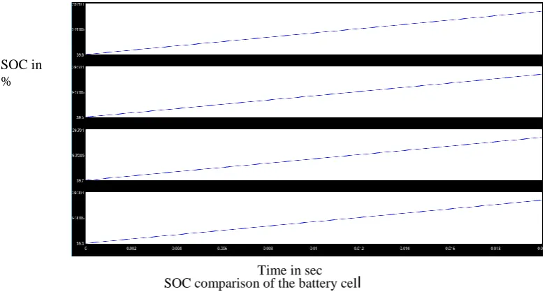
In figure 4 the SOC of the series-connected cells was compared. The SOC of cell 1 is kept higher than other cells since all the cells are in the charging condition. All the cells are in charging condition unrelated SOC % of an individual cell. Therefore no cell balancing has been done in the conventional system.
Fig4: simulation result of the conventional system V. PROPOSED SYSTEM
The evaluation of the charging status of individual cells in the battery is a drawback in BMS and the performance has a large impact on electric vehicles. In an electrical vehicle, safety and reliability are some of the important concerns. In the meantime, a typical EV has a large number of cells connected; it is a bit challenging to measure the individual cell voltage of a battery pack. But, by knowing the individual cell voltage, cell balancing and protection can be performed.
Fig 5: Block diagram convention system
SOC comparison of the battery celTime in sec
l
SOC in%
Charge
controller
DC
source
Buck
converter
Charging and
discharging
switches
ISSN (Print) : 2320 – 3765 ISSN (Online): 2278 – 8875
I
nternational
J
ournal of
A
dvanced
R
esearch in
E
lectrical,
E
lectronics and
I
nstrumentation
E
ngineering
(A High Impact Factor, Monthly, Peer Reviewed Journal)
Website: www.ijareeie.com Vol. 8, Issue 10, October 2019
In the proposed work the buck converter based cell balancing of the battery cell has been done, and SOC of the individual cell has been monitored. The block diagram of the proposed system is shown in fig5. The Bi-directional switches were employed to control the charging and discharging of the cells. The DC supply from the solar panel is given to the buck converter, and the buck converter reduces the input voltage. The buck converters provide supply or activation pulse to the Bi-directional switches. The proposed system consists of two Bi-directional switches, one switch for charging the battery cell, one more switch for discharging purpose. Based on the output of the charge controller the charging and discharging of energy takes place. By the proposed system individual cell monitoring and cell balancing have been done. The bidirectional current transfer is achieved by using Bi-directional switches where charging and discharging of the selected cell can be done by utilizing bi-directional switches.
Fig6: Circuit diagram of the proposed system
The circuit operation of the proposed system is in fig 6. The basic operation of the buck converter is the same when the SD1 is ON, the current flow through the inductor to load, during that period the inductor stores energy in magnetic form. When SD1 is OFF the energy stored in an inductor discharge through the freewheeling diode.in the proposed system Bi-direction switches were used for transfer current, the SOC of the individual cell is analyzed and it compares with the average SOC of the individual SOC. The output is given to a charge controller based on the charge controller either charging switch or discharging switch activated. If the SOC of the cell 1 is high, the comparison of the SOC of the cell 1 compared with the average SOC based on the comparison result the discharging switch will be provided with a high pulse to conduct the discharging switch.
VI. CONCLUSION
In this paper, the different cell balancing topologies where surveyed and active cell balancing based on the buck converter was chosen. In the proposed system battery charging was done with cell balancing topology. The buck converter based battery charging with and without cell balancing was compared using MATLAB Simulink software. By the comparative results, the overall performance of the buck converter based cell balancing is highly efficient.The proposed cell balancing technique enhances the life cycle and efficiency of the battery used for electric vehicles.
REFERENCES
[1]K. Zhi-Guo, Z. Chun-Bo, L. Ren-Gui and C. Shu-Kang, “Comparison and Evaluation of Charge Equalization Technique for Series Connected Batteries, 37th IEEE Power Electronics Specialists Conference, pp. 1-6, 2006.[2] Lee Y, Jeon S, Yun J, Bae S. Comparison of Battery Cell Balancing Methods. Vietnam: Proceedings of International Conference on Information and Convergence Technology for Smart Society (ICICTS „16). 2016; p. 125-26.[3]L. Xi, et al.: "Modularized buck-boost + Cuk converter for high voltage series-connected battery cells," 2012 Twenty-Seventh Annual IEEE Applied Power Electronics Conference and Exposition (APEC) (2012) 2272[4]K. M. Lee, et al.: "Active cell balancing of Li-Ion batteries using the LC series resonant circuit,” IEEE Trans. Ind. Electron(2005)549
[5] T. Ming and T. Stuart, "Selective buck-boost equalizer for series battery packs," Aerospace and Electronic Systems, IEEE Transactions on, vol. 36, pp. 201-211, 2000
ISSN (Print) : 2320 – 3765 ISSN (Online): 2278 – 8875
I
nternational
J
ournal of
A
dvanced
R
esearch in
E
lectrical,
E
lectronics and
I
nstrumentation
E
ngineering
(A High Impact Factor, Monthly, Peer Reviewed Journal)
Website: www.ijareeie.com Vol. 8, Issue 10, October 2019
[7] L Yuang-Shung, D. Chun-Yi, C. Guo-Tian, and Y. Shen-Ching, Battery Equalization Using Bi-directional Ćuk Converters in DCVM Operation, IEEE, 36th Power Electronics Specialists Conference, PESC '05, pp. 765–771, 2005[8] S.W. Moore, and P. J. Schneider, "A Review of Cell Equalization Methods for Lithium-Ion and Lithium Polymer Battery Systems," Society of Automotive Engineers, 2001.
[9] Analysis, Design, and Experimental Validation of a Primary Side Current-Sensing Flyback Converter for Use in a Battery Management System Borislav Dimitrov 1,*, Muthu Krishna 1 , Andrew Cruden 1 , Suleiman Sharkh 1 and Ahmad Elkhateb 2 published article in march 2018[10]Siyang Zhao, Junming Zhang, Yang Shi, “A Low cost, low power flyback converter with a simple transformer”, 2012 IEEE 7th International Power Electronics and Motion Control Conference - ECCE Asia, June 2-5, 2012, Harbin, China.
[11]João Paulo M. Figueiredo and Fernando L. Toffoli, “COMPARISON OF NONISOLATED DC-DC CONVERTERS FROM THE EFFICIENCY POINT OF VIEW”.
[12] Mohamed Daowd, Noshin Omar, Peter Van Den Bossche, Joeri Van Mierlo,” A Review of Passive and Active Battery Balancing based on MATLAB/Simulink”, International Review of Electrical Engineering (I.R.E.E.), Vol. xx, n. x