Simulation and Implementation of Loop Based
Bank Locker Security System Using Cost
Effective Microcontroller and GSM Module
M.Muruganandam
1, A.Maswoodhur Rahman
2 Lecturer, Ibri College of Technology, Ibri, Sultanate of Oman1Lecturer, Ibri College of Technology, Ibri, Sultanate of Oman2
ABSTRACT: Nowadays almost all the part of the world, bank-theft is happening causally. Bank locker security is very important, to protect any kind of properties from thieves. This project is developed with simple loop, which will provide security for the bank locker by giving the alarm signal. Also this system will give the alert SMS to the bank manager. This system can be implemented in anywhere to provide security, where the device is movable. In this project bank locker door is considered for providing the security. This system is simulated using Proteus 8 software and then it is implemented with hardware module. A Triac BT136 and a Transistor BC547 are used to supply the alarm to provide the sound. A micro-controller and a GSM module are used to send SMS alert.
KEYWORDS: Arduino uno microcontroller, GSM, Proteus, Triac, Transistor, Phone and Buzzer.
I.INTRODUCTION
In recent years, there are many thefts occurring in banks. Even we are reading this kind of news in the newspapers and watching in TV channels, in our daily life. As technology continues to grow, the need for safe and secure cabinets continues to increase. A solution to this problem can address this paper.
The main objective of this paper is to protect the bank locker from thief by using an alarm signal and an alert SMS. In most of the banks, no proper security system, hence many thefts happen in the banks. This paper is proposed to give proper security for the banks by providing the alarm and alert SMS in case of any theft, by opening the bank door. In this project simple loop based circuit using transistor, triac, Arduino Uno and SIM 900 GSM module were used. A loop wire is fixed in the door opening place; in such a way that the door opens the loop will cut. The circuit is designed that the loop is opened then the buzzer will give alarm, to alert the bank security staff, also an alert SMS will send to concern person. Hence the theft may be avoided by using the loop based security system and hence the bank properties will be protected.
II. LITERATURE SURVEY
A bank locker security system based on RFID and GSM technology were implemented and which can activate, authenticate, and validate the user and unlock the door in real time for bank locker secure access. The main advantage of using passive RFID and GSM is more secure than other systems [4-10]. RFID systems are often more expensive. RFID technology is harder to understand also can be less reliable. The security system contains a microcontroller, keypad, GSM module and LCD display. By using keypad it is needed to enter the password that is provided to the authenticated persons [11]. But in some cases the password may forget, hence the password based security system is not advisable.
In order to provide security system for social safety, the IOT based authentication is utilized. They designed an advance security system which will ensure the genuine access of the locker overcoming all the misuses. For this we are using unique password technique, password verification and lastly the OTP verification [12]. Ultimately the system utilizes the regular passwords and OTPs. A complete literature survey has been taken in [14] about all the following techniques which is used for security systems. Those are Password based, Biometric based, GSM based, Smart card based, RFID based, Door phone based, Bluetooth based, Social networking sites based, OTP based, Motion detector based, VB based and Combined systems [13]. All the above mentioned methods result certain drawbacks in terms of cost, complication, and uncertainty.
The proposed system is simple loop based security system with less cost. This system will provide alarm signal as well as alert SMS. Here triac is used as a switching device, hence once the bank locker door opened by any unauthorized person, the buzzer will continuously ring even the person again close the door until switch off the main power supply to the circuit. It is the main advantage of the system also the system can be developed with cost effective.
III. BLOCK DIAGRAM OF THE PROPOSED SYSTEM
Fig. 1 Block Diagram of Proposed System
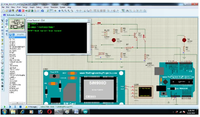
IV.CIRCUIT DIAGRAM AND SIMULATION
The circuit diagram of proposed system is given in figure 2.The major devices used in the circuit are Arduino Uno, GSM SIM900 Module, transistor and triac. The power supply consists of transformer, diode and capacitor, which will supply 12V DC to the circuit. There is a loop wire used to sense the door opening. One end of the loop wire is connected to the base of the NPN transistor and another is grounded.
Fig. 2 Block Diagram of Proposed System
Fig. 3 Simulation circuit before locker door open
Fig. 4 Simulation circuit after locker door open
The 680 resistor is used to limit the LED current. 12K and 10K resistors are the pull up and pull down resistor for the transistor and triac respectively. The 33 and 470 resistors are also for current limiting purpose.
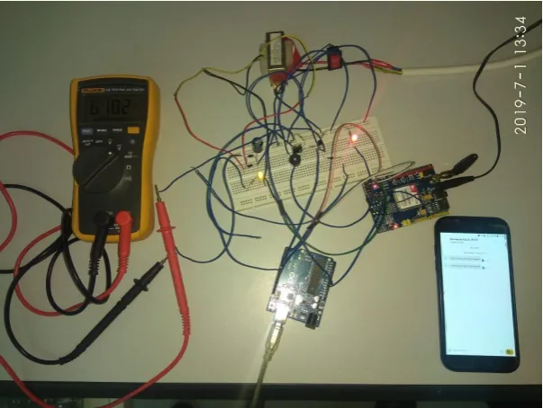
IV.HARDWARE CIRCUIT
Fig. 5 Hardware circuit before loop open
The figure 5 displays the hardware circuit of the proposed system. The circuit is tested using bread board. Connections were made as per the circuit diagram. The loop wire is used as sensor for bank door opening and closing. When we open the loop, the circuit is working properly same as simulation, it will gives buzzer sound, LED indication and the alert SMS. The figure 6 exhibit the working of the hardware circuit when the loop open and the figure 7 the screen shot of the alert SMS.
Fig. 7 Screen short of the alert SMS
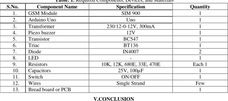
The table 1 provides the details of the list of components utilized for the proposed work and the figure 9 shows the Arduino Code of the proposed project.
Table. 1. Required Components, Devices, and Materials
S.No. Component Name Specification Quantity
1. GSM Module SIM 900 1
2. Arduino Uno Uno 1
3. Transformer 230/12-0-12V, 300mA 1
4. Piezo buzzer 12V 1
5. Transistor BC547 1
6. Triac BT136 1
7. Diode IN4007 2
8. LED - 1
9. Resistors 10K, 12K, 680E, 33E, 470E Each 1
10. Capacitors 25V, 100µF 1
11. Switch ON/OFF 1
12. Wires Single Strand Few
13. Bread board or PCB 1
V.CONCLUSION
We have developed a loop based bank locker security system using Arduino and GSM module to protect the bank properties from thieves. According to our objective, in the event of any theft in the bank, this system will work and alert the security staff by giving continuous alarm and alert SMS. As soon as the bank door is opened by thief, automatically it sounds through the buzzer also the LED light will glow and SMS will sent to the higher officials. At first we designed and tested using Proteus 8software and we checked the operation by opening the loop manually. Then we developed the circuit with bread board and tested the circuit with the proto type model. It was working properly. The main advantage of the proposed work is very simple circuit and low cost to implement. Thus, we conclude that the proposed work will be fully suitable for any where that security is needed for movable objects.
REFERENCES
[1]. https://electronicsforu.com/electronics-projects/loop-based-anti-theft-alarm
[2]. AmbrishKumar,Anish Kumar, KushagraGohil, LaxitPorwal, Manish Cheepa and Ankit vijayvargiya, “Fingerprint Based Bank Locker with Image Capture”, published in International Journal of Advanced in Management, Technology and Engineering Sciences, Volume 8, Issue III, MARCH/2018, ISSN NO : 2249-7455
[4]. Ch.Sumalatha, A.Viyayamanasa, K.Ramasrujana, I.Meghamala, K.LakshmiPrasanna, K.Hema Rani, “Bank Locker Security System Using RFID and GSM Technology”, published in International Journal for Research in Applied Science & Engineering Technology (IJRASET), Volume 4 Issue IV, April 2016, ISSN: 2321-9653.
[5]. R.Ramani, S. Selvaraju, S.Valarmathy and P.Niranjan, “ Bank Locker Security System based on RFID and GSM Technology”, published in International Journal of Computer Applications (0975 – 8887) Volume 57– No.18, November 2012.
[6]. Khaing Mar Htwe, Zaw Min MinHtun and HlaMyoTun, “Design and Implementation of Bank Locker Security System Based on Fingerprint Sensing Circuit and RFID Reader”, published in International Journal of Scientific & Technology Research, Volume 4, Issue 07, July 2015 ISSN 2277-8616, 2015.
[7]. Hiloni S. Detroja, Prutha J. Vasoya, Disha D. Kotadiya and C. B. Bambhroliya. “GSM Based Bank Locker Security System using RFID, Password and Fingerprint Technology”, published in International Journal for Innovative Research in Science & Technology, Volume 2, Issue 11, April 2016, ISSN (online): 2349-6010
[8]. S.V.Tejesvi, P.Sravani, M.L.Mythili, K.Jayanthi, P.Nagesh Kumar and K.Balavani, “Intellectual Bank Locker Security System”, published in International Journal of Engineering Research and Applications, Vol. 6, Issue 2, (Part - 2) February 2016, pp.31-34, ISSN: 2248-9622 [9]. Sachin S. Malode1, Dr. S.B. Patil, “Advanced Security System for Bank Lockers Using Biometric and GSM”, published in International
Research Journal of Engineering and Technology (IRJET) Volume: 04 Issue: 12, December-2017, E-ISSN: 2395-0056 P-ISSN: 2395-0072. [10]. Aruna.D.Mane and SirkaziMohdArif, “Locker Security System Using RFID and GSM Technology”, published in International Journal of
Advances in Engineering & Technology, May 2013. Vol. 6, Issue 2, pp. 973-980, ISSN: 2231-1963.
[11]. P V L N Phani, O Narendra Kumar Reddy, R Manisha Reddy, “Keypad Based Bank Locker Security System Using Gsm Technology”, published in International Journal of Research in Engineering and Science (IJRES), Volume 3, Issue 1, Jan. 2015, PP.48-53, ISSN (Online): 2320-9364, ISSN (Print): 2320-9356.
[12]. U.K. Thakur, BhupeshMankar, DigvijayRaut, AkashBobde and Ishant moon, “Performance Survey on IOT Based SecuritySystem for Social Safety”, published in International Journal of Innovative Research in Computerand Communication Engineering, Vol. 6, Issue 10, October 2018, ISSN(Online): 2320-9801, ISSN (Print) : 2320-9798