Design and Analysis of Grid-Connected Pv Systems With
Generation Of Constant Power
1G.SRINIVASA RAO, 2N.RAMESH
1Assistant professor, Sreyas Institute of Engineering and Technology. 2
Assistant professor, Sreyas Institute of Engineering and Technology.
ABSTRACT : In this paper an improved control strategy is implemented the incremental method of the maximum power which is feed to the PV systems and it is proposed to make sure about the smooth and fast transition between Constant Power Generation (CPG) and maximum power point tracking ,and also by the proposed control strategy we can always achieved the stable operation, Regardless of the solar irradiance levels and high-performance. Therefore fuzzy controller is also implemented in this project, because fuzzy controller work like a human decision-making mechanism, providing the operation of an electronic system with decisions of experts.and this fuzzy control is compared with the other controller. Which can be regulate by the PV output power according to any set-point, and it also force the PV systems to operate at the left side of the maximum power point without any stability problems. Simulation results have been verified in the effectiveness manner by using the proposed CPG control in terms of high accuracy, stable transitions , and fast dynamics.
Index Terms—Active power control, constant power
control, maximum power point tracking, PV systems,
power converters, Fuzzy controller. INTRODUCTION
In the recent year , Maximum Power Point Tracking (MPPT) operation is necessary in the grid-connected PV systems in order to get the maximize power from the energy yield. PV installations is need for the advance power control schemes and along with the regulations to decrease impacts from PV systems such as the overloading the power grid . For the German Federal Law: Renewable Energy Sources Act in which the PV systems with the rated power below 30 kWp which have the limit for the maximum which is feed to the power (e.g. 70 % of the rated power) which can be remotely controlled by the utility like the active power control which is refered as the Constant Power Generation (CPG) control or an absolute power control which is described in the Danish grid code in which CPG concept which have been presented which is reveals by the most cost-effective way to achieve the CPG control is by modifying the MPPT algorithm at the PV inverter level.
{
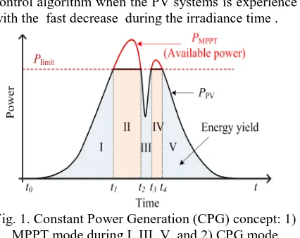
Moreover , when ever the output power reach the Plimit, then the output power of the PV system will be kept constant, i.e., Ppv = Plimit, which leading to the constant active power which is injected as shown in (1) and it also illustrated in Fig. 1 In terms of the algorithms and the CPG which is based upon the Perturb and Observe (P&O-CPG) algorithm which was introduced by the single stage PV systems . moreover during the operating area of the CPG control which is limited at the right side of the Maximum Power Point (MPP) of the PV arrays (CPP-R), due to its single-stage configuration. Unfortunately it will reduce the robustness of the control algorithm when the PV systems is experience with the fast decrease during the irradiance time .
Fig. 1. Constant Power Generation (CPG) concept: 1) MPPT mode during I, III, V, and 2) CPG mode
during II, IV [6].
Fig. 2. Stability issues of the conventional CPG algorithms, when the operating point is normally
located at the right side of the MPP.
Both the P&O-CPG algorithm can be applied to any two-stage single-phase PV system .
CONVENTIONAL CPG ALGORITHM System Configuration
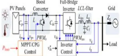
As shown in the Fig. 3 shows the basic hardware configuration of the two-stage single-phase grid-connected PV system and its control structure. The CPG control is developed in the boost converter, which have been explained in the next section.
Fig. 3. Simulation of schematic and overall control structure of a two-stage singlephase grid-connected
PV system
The full-bridge inverter control is realized by the cascaded control ,here the DC-link voltage is kept constant throughout the control of the AC grid current, which is an inner loop . an active power is injected to the grid, which meaning that the PV system operates at a unity power factor. Not only that have been mentioned above and the two-stage configuration can extend the operating range of both the MPPT and CPG algorithms. In the two-stage case, the PV output voltage vpv can be lower (e.g., at the left side of the MPP), and then it can be stepped up by the boost converter to match the required DC-link voltage (e.g., 450 V) [10].
Operational Principle
The operational principle of the conventional P&O-CPG algorithm is illustrated in Fig. 4. It can be divided into two modes: a) MPPT mode (Ppv Plimit), where the P&O algorithm should track the maximum power; b) CPG mode (Ppv > Plimit ), where the PV output power is limited at Plimit. During the MPPT operation, the behavior of the algorithm is similar to the conventional P&O MPPT algorithm - the operating point will track and oscillate around the MPP [13].
Fig. 4. Operational principle of the Perturb and Observe based CPG algorithm (P&O-CPG), where the operating point is regulated to the left side of the
MPP considering stability issues.
In the case of the CPG operation, the PV voltage vpv is continuously perturbed toward a point referred to as Constant Power Point (CPP), i.e., Ppv = Plimit. After a number of iterations, the operating point will reach and oscillate around the CPP. Although the PV system with the P&O-CPG control can operate at both CPPs, only the operation at the left side of the MPP (CPP-L) is focused for the stability concern. The control structure of the algorithm is shown in Fig. 5, where v* pv can be expressed as
{
where vMPPT is the reference voltage from the MPPT algorithm (i.e., the P&O MPPT algorithm), vpv,n is the measured PV voltage, and vstep is the perturbation step size.
Fig. 5. Control structure of the Perturb and Observe based CPG algorithm (P&O-CPG), where a
Proportional Integrator (PI) is adopted. Issues Of The P&O-CPG Algorithm
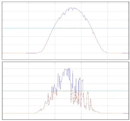
Fig. 6. simulation results of the Perturb and Observe based CPG algorithm (P&O-CPG) under two daily
conditions: (a) clear day and (b) cloudy day. This can be further explained using the operation trajectory of the PV system presented in Fig. Assuming that the PV system is operating in MPPT mode initially and the irradiance level suddenly increases, the PV power Ppv is basically lifted by the change in the irradiance, as it can be seen from the black arrow trajectory (i.e., A!B!C). As a consequence, large power overshoots may occur. Similarly, if the PV system is operating in the CPG operation (e.g., at CPP-L) and the irradiance suddenly drops, the output power Ppv will make a sudden decrease, as shown in Fig. (i.e., CID). It will take a number of iterations until the operating point reaches the new MPP (i.e., E) at that irradiance condition (i.e., 200 W/m2), and resulting in loss of power generation.
Fig. 7. Operating trajectory of the algorithm during a fast changing irradiance condition resulting in overshoot (black arrow) and power losses (orange
arrow).
HIGH-PERFORMANCE P&O-CPG ALGORITHM
According to the above, two main tasks exist - minimizing the overshoots and minimizing the power losses during the fast changing irradiance condition which has to be addressed in the case of CPG operation. The proposed high-performance P&O-CPG algorithm can effectively solve those
issues. A. Minimizing Overshoots Increasing the perturbation step size is a possibility to minimize the overshoots as the tracking speed is increased. Specifically, a large step size can reduce the required number of iterations to reach the corresponding CPP. Notably, the step size modification should be enabled only when the algorithm detects a fast increase in the Irradiance Condition (IC), which can be illustrated as
{
with Ppv,n being the measured PV power at the present sampling, and "inc being the criterion, which should be larger than the steady-state power oscillation of the PV panels. When a fast increase in the IC is detected (i.e., IC = 1), an adaptive step size is then employed, where the step size is calculated based on the difference between Plimit and Ppv,n as it is given in (4). By doing so, the large step size will be used initially and the step size will continuously be reduced as the operating point approaches to the CPP.
[( ) ]
where vpv is the reference output voltage of the PV arrays, vpv,n and Ppv,n are the measured output voltage and power of the PV array at the present sampling, respectively. Pmp is the rated power. vstep is the original step size of the P&O-CPG algorithm. The term Plimit=Pmp is introduced to alleviate the step size dependency in the level of Plimit. is a constant which can be used to tune the speed of the algorithm.
Minimizing Power Losses
As explained in Fig. when the CPG operating point is at the left side of the MPP, the P&O-CPG algorithm requires a number of iterations to reach the new MPP during a fast decease in irradiance, leading to power losses. In fact, the operating point of the PV system does not change much if the PV system is operating in the MPPT under different irradiance levels as shown in Fig. 8. Notably, the detection of the decreased IC as well as the Previous Operating Mode (POM) is also important for minimizing the power losses:
{
{ | | | |
than the steady-state error in the PV power of the P&O-CPG algorithm. When a fast decrease (i.e., IC = 1) is detected during the CPG to MPPT transition according to (6), a constant voltage given by (7) is applied to the PV system in order to accelerate the tracking speed (i.e., minimize the power losses). The constant voltage can be approximated as 71-78 % of the opencircuit voltage VOC, as illustrated in Fig. 7 .
Fig. 7. Power-voltage (P-V) curves of the PV arrays, where the voltage at the MPP is almost constant
especially at a higher irradiance level . By doing so, the operating point can be instantaneously moved close to the MPP in one perturbation, resulting in a significant reduction in the number of iterations until the operating point reaches the MPP. This approach is simple but effective, which is very suitable to be implemented.
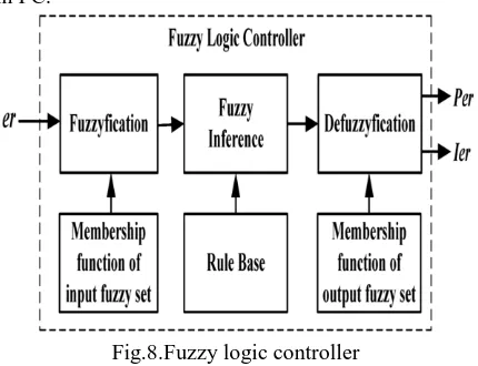
FUZZY LOGIC CONTROLLER
In FLC, basic control action is determined by a set of linguistic rules. These rules are determined by the system. Since the numerical variables are converted into linguistic variables, mathematical modeling of the system is not required in FC.
Fig.8.Fuzzy logic controller
The FLC comprises of three parts: fuzzification, interference engine and defuzzification. The FC is characterized as i. seven fuzzy sets for each input and output. ii. Triangular membership functions for simplicity. iii. Fuzzification using continuous universe of discourse. iv. Implication using Madman‟s, „min‟ operator. v. Defuzzification using the height method.
TABLE I: Fuzzy Rules
Fuzzification: Membership function values are assigned to the linguistic variables, using seven fuzzy subsets: NB (Negative Big), NM (Negative Medium), NS (Negative Small), ZE (Zero), PS (Positive Small), PM (Positive Medium), and PB (Positive Big). The Partition of fuzzy subsets and the shape of membership CE(k) E(k) function adapt the shape up to appropriate system. The value of input error and change in error are normalized by an input scaling factor.In this system the input scaling factor has been designed such that input values are between -1 and +1. The triangular shape of the membership function of this arrangement presumes that for any particular E(k) input there is only one dominant fuzzy subset. The input error for the FLC is given as
E(k) =
(23) CE(k) = E(k) – E(k-1) (24) Inference Method: Several composition methods such as Max–Min and Max-Dot have been proposed in the literature. In this paper Min method is used. The output membership function of each rule is given by the minimum operator and maximum operator. Table 1 shows rule base of the FLC.
Defuzzification: As a plant usually requires a non-fuzzy value of control, a defuzzification stage is needed. To compute the output of the FLC, „height‟ method is used and the FLC output modifies the control output. Further, the output of FLC controls the switch in the inverter.The set of FC rules are derived from
u=-[α E + (1-α)*C] (14)
Fig: 10 change as error membership functions
Fig: 11 output variable Membership functions Where α is self-adjustable factor which can regulate the whole operation. E is the error of the system, C is the change in error and u is the control variable.
SIMULATION VERIFICATION
Solutions to improve the dynamic performance of the P&OCPG algorithm have been discussed above. Parameters of the proposed high-performance P&O-CPG algorithm are designed as: = 10, k = 0.715, "inc = 50 W, "dec = 100 W, and "ss = 30 W.simulation are carried out referring to Fig. 3, and the system parameters are given in Table I.
Table II
Parameters Of The Two-Stage Single-Phase PV System
In the simulation, a 3-kW PV simulator has been adopted, where real-field solar irradiance and ambient temperature profiles are programmed. Fig. 8 shows the performance of the proposed high performance P&O-CPG method with two real-field daily conditions. In contrast to the conventional P&O-CPG method (shown in Fig. 6), the overshoots and power losses are significantly reduced by the proposed solution and a stable operation. is also maintained. The algorithm also has a selective behavior to only react, when the fast irradiance condition is detected. This can be seen from the performance under clear irradiance conditions in Fig.
8(a), which is similar to the conventional P&O-CPG algorithm (shown in Fig. 6(a)).
Fig. 12. simulation results of the proposed high-performance P&O-CPG algorithm under two daily
conditions: (a) clear day and (b) cloudy day. CONCLUSION
In this paper observed that a high-performance active power control scheme been limiting the maximum power which is feed to the PV systems which is proposed there. The proposed solution makes sure about the stable constant power generation operation. When compared with the traditional methods. Here the proposed control strategy will forces the PV systems to operate at the left side of the maximum power point, and which make to achieve a stable operation along with smooth transitions. By using fuzzy control we can performance will be better when comparing with other controller. fuzzy controller is used to minimized the power losses, reduced overshoots and also fast dynamics. Moreover for single-stage PV systems, same concept of CPG is also applicable. Therefore in such case, the PV voltage operating range will limited and some small changes in the algorithms which are necessary to make sure for a stable operation.
REFERENCES
[1] T. Stetz, F. Marten, and M. Braun, “Improved low voltage gridintegration of photovoltaic systems in Germany,” IEEE Trans. Sustain. Energy, vol. 4, no. 2, pp. 534–542, Apr. 2013.
Electron., vol. 29, no. 12, pp. 6271–6275, Dec. 2014. [4] German Federal Law: Renewable Energy Sources Act (Gesetz fur den Vorrang Erneuerbarer Energien) BGBl, Std., July 2014.
[5] Energinet.dk, “Technical regulation 3.2.5 for wind power plants with a power output greater than 11 kw,” Tech. Rep., 2010.
[6] Y. Yang, F. Blaabjerg, and H. Wang, “Constant power generation of photovoltaic systems considering the distributed grid capacity,” in Proc. of APEC, pp. 379–385, Mar. 2014.
[7] R. G. Wandhare and V. Agarwal, “Precise active and reactive power control of the PV-DGS integrated with weak grid to increase PV penetration,” in Proc. of PVSC, pp. 3150–3155, Jun. 2014.
[8] W. Cao, Y. Ma, J. Wang, L. Yang, J. Wang, F. Wang, and L. M. Tolbert, “Two-stage PV inverter system emulator in converter based power grid emulation system,” in Proc. of ECCE, pp. 4518– 4525, Sept. 2013.