OPERATING PRINCIPLES
OF THE
®
UNIVAC FILE-COMPUTER
ISSUED JANUARY 1, 1956
REMINGTON RAND UNIVAC
DIVISION OF SPERRY RAND CORPORATION
OPERATING PRINCIPLES UNIVAC FILE-COMPUTER
INDEX
I. Introduction
II. General Components of Univac File-Computer III. Input - Output Equipment
IV. Storage Components
V. Arithmetic
&
Control Section -- Programming VI. Illustrative Problems and SolutionsILLUSTRATIONS
FIGURE NO. DESCRIPTION
I. General Schematic of Univac File.Computer 2. Diagram and Explanation of Feeding
Sequence - 150 CPM - 90 column
3. 150 CPM - Data Flow between device, its plugboard and the computer
4. Schematic of 150 CPM Card Sensing Circuitry 5. Schematic of Magnetic Drum Recording
6. The Small or Hi-Speed Drum
7. Functional Diagram of Hi-Speed Storage Drum 8. Intermediate Storage
9. Large Capacity Drum
10. Illustration of Large Capacity Drum Address Numbering System
11. Large Capacity Drum Circuitry
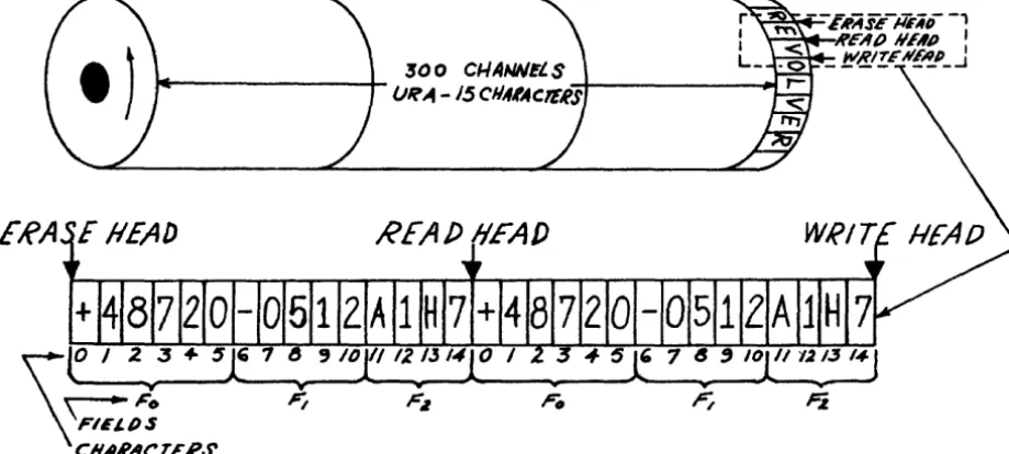
12. Schematic of Revolver URAls and fields 13. Schematic of a Selector
14. Schematic of Program Select and Selector Operation 15. Schematic of Input Control
PAGE NO. II - 5
III - 4
III - 1 III - 12
IV - 4 IV - 6 IV - 7 IV - 10 IV - 14 IV - 17
SECTION I
I - I
INTRODUCTION TO THE UNIVAC FILE-COMPUTER.
The Univac File-Computer System is a medium sized electronic system designed to combine efficiently electronic computing with large cap-acity internal magnetic drum storage for random access processing of unsorted data. It possesses common language versatility and many types of input-output may be used simultaneously. Input-output units and storage units can be put together as building block units to pro-duce a system satisfying individual requirements. The five basic components of any computer system are input, storage, arithmetic, control and output. The Univac File-Computer has these components but the type, number and capacity of these units in any grouping of equipment is determined by the individual application requirements. Expanding requirements for better control of the basic business func-tions have dictated the need for computers with larger and larger internal storage systems. After carefully studying many business problems it was determined that this storage should possess a format for storing data similar to the form of the business transaction. This basic typical form is the individual unit record which is an extension of that common to punched card systems. In payroll we are concerned with the employee. Inventory control problems require the handling of single items successively. Sales analysis, material con-trol, billing and invoicing and virtually every other business prob-lem deal with individual unit records. This format then, has been adapted as the layout for storing data within the system. This lay-out, together with the user's ability to specify the desired length of this record allows maximum utility of the large storage capacity available in the Univac File-Computer.
An evaluation of the Univac File-Computer's potential in solving problems involving high volume processing of unsorted data can be best made by examining its versatility.
STORAGE VERSATILITY
The large-scale random-access internal memory permits instant refer-ence to stored unit records which include all the control figures and master data required for the complete processing of each input item. This random-access storage feature permits entry of the input data to
1 - 2
INPUT-OUTPUT VERSATILITY.
Another trail-blazing feature is the simultaneous operation of up to 31 universal language input-output units -- any combination of
punched-card, magnetic tape, perforated tape, line printer, electric typewriter, ten-key tape printer, and key punch units.
This unusual flexibility opens the way for practically unlimited in-novations of procedures to solve particular problems of data pro-cessing and reference to stored data. In particular, it permits a direct tie-in with automated recording of the transaction items to be used as input data, and with automated methods for utilizing out-put data from the system.
PROGRAMMING VERSATILITY.
Processing of each input item can include many computations and logi-cal decisions based on simultaneous reference to both the input data and the stored data (balances, to-date totals, rates or prices, etc.). Output of results can be made immediately -- including stored master descriptions, etc.
As part of the same processing, all stored balances and totals can be brought forward to reflect the item processed maintaining com-plete control figures on a truly current basis.
Several applications can be combined into a single high-speed process-ing. For example, billing can be combined with inventory control and sales statistics -- requiring only a single processing run of each customer order. Similarly, a production control system that includes both machine loads and operation schedules requires only a single processing for each work order and each job ticket. Complex mathe-matical problems can be completed in a single pass of a punChed-card deck.
The combination of multiple input and expandable programming capacity permits the simultaneous processing of many different types of data with each input item processed selectively according to its own re-quirements.
REPORTING VERSATILITY.
All the data held in random-access storage is instantly available by keyboard inquiry when needed, eliminating any need to search records or wait until records are available.
1 - 3
Another capability is the immediate reporting of any condition re-quiring supervisory attention, at the instant such a condition devel-ops during normal data-processing runs. Such reports can be printed out directly on an input-output unit located in the supervisory office concerned, and keyboard inquiry can also be made directly from that office for any stored information required.
BUILDrNG-BLOCK VERSATILITY.
The wide choice of input-output and storage units permits the design-ing of a system which is truly specific to the particular
data-processing needs. Additional units may be added to the system at any time to meet expanded needs.
The flexibility of the Univac File-Computer System also will permit the introduction of future developments in data-processing equipment and techniques without the danger of obsolescence for the complete system.
SECTION II
1. 2. 3. 4. 5.
GENERAL COMPONENTS OF THE UNIVAC FILE-COMPUTER.
INDEX - SECTION II
General Input-Output Storage
Arithmetic
&
ControlGeneralized Schematic of Entire System
PAGE NO.
II - 1
I. GENERAL
The Univac File-Computer, as all computers, can be analyzed by func-tion or components. These computer funcfunc-tions or requirements are:
A. Input
B.
Output C. Storage D. Arithmetic E. ControlAll computers require components of one form or another to accomplish these five functions. As an example of this we might analyze a lO-key adding machine in light of these requirements and we would find that each of the functions is fulfilled as follows:
A. Input -- Keyboard digit keys 0 -- 9
B. Output -- Printed tape of input data and totals C. Storage - The accumulating register which
remem-bers and carries the total forward. D. Arithmetic
--The accumulating register which adds or subtracts the input data to arrive at a total
E. Control - The motor bar, repeat key, sub-total key and subtract key.
As can be seen by the above analogy all computers contain these five functions in one form or another and, of course, in varying degrees of capaci ty.
The form these functions take in the Univac File-Computer are listed in this section along with a general explanation of how data is processed through the system. Subsequent sections describe the de-tail operating characteristics and use of each of the components men-tioned.
II - 2
A. 90 Column card sensing punching unit - 150 CPM B. 90 Column card sensing punching unit 200 CPM C. 80 Column card sensing punching unit - 200 CPM D. Inquiry Keyboard
E. Typewriter with paper tape and plugboard format control
1. Paper tape reader -- 20 characters per second 2. Paper tape punch -- 20 characters per second F. Paper tape reader -- 200 characters per second G. Paper tape punch -- 60 characters per second H. Key Punch - 90 column
1. Magnetic Tape Plas'tic
J. Magnetic Tape Metallic - Compatible with Univac K. High-Speed Printer
Any combination of these devices in any total number from one (1) to thirty one (31) may be included in anyone Univac File-Computer System. Since each device is equipped with its own buffer storage, multiple device systems can share the computer through direction of the multiplex function (see section V for detail operation).
3. STORAGE (See Section IV for detailed characteristics and operation) There are five basic storage sections within the Univac File-Computer, of which one is composed of magnetic cores, while the remaining four types are magnetic drum storages. The five storage sections and their respective access speeds and capacities are:
A. Input-Output Buffer Storages -- Magnetic Cores These storages act as a translator medium between the input-output device and the computer
II - 3
B. Input Drum Storages -- Magnetic Drum 12,000 RPM These storages are used by the computer for ob-taining input data from and delivering output data to the input-output buffer storages.
There are ten (10) stoLages of twelve digit cap-aCity each for every input-output device in-cluded in the system. The average access time to any input storage is 2.5 milliseconds.
C. Intermediate Storages -- Magnetic Drum 12,000 RPM This storage section is used to retain constant or intermediate computing results. Either thirty
(30) or fifty (50) of these twelve digit storages may be included in a system. Average access to any storage is 2.5 milliseconds.
D. Program Storage -- Magnetic Drum 12,000 RPM
For additional program capacity (over and above the plugboard) additional storages may be in-cluded in a system. These storages may be used to store either three address program instruc-tions, results, or constant data. Average access time to any of these storages is 2.5 milliseconds. E. Large Capacity Storage -- Magnetic Drums 1,750 RPM
Large capacity drum storage is used for storing file reference data, summarized results or vola-tile file data. Each unit or drum can store up to 180,000 characters of data and a total of ten (10) drums can be included in one system to ob-tain a total of 1,800,000 characters of storage. The average access time to any set of characters in this storage sections is 17 milliseconds. External storage in the form of magnetic tapes or cards is also avail-able.
4. ARITHMETIC AND CONTROL (See Section V for detailed operating instruc-tions)
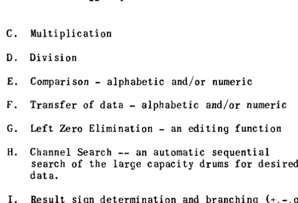
The arithmetic section of the machine provides the necessary circuit-ry to perform the data processing functions upon the stored informa-tion. The functions provided for in the Univac File-Computer are:
II - 4
C. Multiplication D. Division
E. Comparison - alphabetic and/or numeric F. Transfer of data - alphabetic and/or numeric G. Left Zero Elimination - an editing function H. Channel Search -- an automatic sequential
search of the large capacity drums for desired data.
I. Result sign determination and branching (+.-,0)
The control section of the machine provides the means of linking and directing these processes of the arithmetic section to operate in a
logical, pre-determined manner upon the stored data.
A. External Programming: Control Panel of 48 non-sequential reusable three address steps.
B. Internal Programming: Stored instructions from hi-speed drum to provide additional three address steps.
Both of these means of control can be utilized in anyone system.
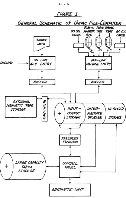
5. GENERAL SCHEMATIC OF ENTIRE SYSTEM
Figure 1 illustrates the general flow of data within a complete system utilizing all major components.
II - 5
FIGURE
1-GENERAL
ScHEMATICON-LINE
INQUIRY • J<EY ENTRY
EXTERNAL MA6NErIC TAPE
STDRAGE
MlLTIPLEX
FlJNCTION
CONTROL
OFF-UN£'
MACHINE
ENT'R
INTER-M~OIATE
STOFA6E
$lOPA5E
LARGE CAPAcITY [)RUM
5TQi<AGE
PflNEL w.--~
III - 1
1. GENERAL
This section deals with the detailed operational characteristics of all the various input-output devices which may be included in a Univac File-Computer system. A section has also been included to deal with the multiplex adapter control necessary for multiple device systems. The general format of data pertaining to each of the devices is as follows;
1) Description of media utilized by the device
2) Operation and function of the manual operating con-trols and indicators
3) Diagrams of the feeding sequence and functions 4) Diagram and explanation of the plugboard related to
the device
5) Timing chart of the control functions
6) Explanation of verification checks related to the device
7) Program planning sheet for the device
8) Physical measurements and installation requirements
III - 2
2. 90 COLUMN CARD SENSING PUNCHING UNIT - 150 CPM
I} Input-Output Media: Ninety column punched cards, each column containing six punching positions i.e. {0.1.3,5,7,9} The punching codes are:
0 1 2 3 4 5 6 7 8 9 A B C 0 E F G H
0 x x x x
I x x x x x
3 x x x x x
5 x x x x x x
7 x x x x x x
9 x x x x x x x
I J K L M N 0 P Q R S T U V W X Y Z %
0 x x x x x x x x
1 x x x x x x x
3 x x x x x x x x x x
5 x x x x x x x x x
7 x x x x x x x x x
9 x x x x x x x x
2) Operation & Function of the Manual Operating Controls & Indicators POWER (Circuit Breaker) SWITCH is located near the front of the machine on the left side just below the Control Panel. This switch serves to turn On and Off all current to the 150 CPM Card Unit and 150 CPM Card Adapter Unit from the main power supply.
MOTOR (Toggle Switch) - This switch serves to turn On and Ofr the current to the Motor of the 150 CPM Card Unit. The Power Switch must be On as well as the Motor Switch before the current will flow to the Motor.
AUTO. FEED (Toggle Switch) - This switch is set On or Off to obtain one of the following two card feeding operations:
On - (Continuous) - After card feeding has been started, it will continue automatically. The last card from the Card Feeding Magazine will feed completely through the machine to the Card Receivers.
Off - (Single Cycle) - After card feeding has been started, only one card will be fed or one machine cycle taken. CARD FEED (Throw Switch) - This switch is moved momentarily either up or down to one of the following two positions. The switch returns to the center position when released.
III - 3
When the machine is set for automatic card feeding, only one movement to the Start position is necessary. The card feeding will continue automatically following that initial impulse.
When the machine is set for single cycle operation, this switch is moved to the Start for each card feeding cycle desired. To feed one card completely through the machine, three machine cycles are required.
STOP - To obtain optional stopping during an automatic run, this switch is moved momentarily to the DOWN position. Card feeding will stop at the conclusion of the current Program.
UNIT (Throw Switch) - This is a safety switch used in conjunction with either the Clear Switch to its right, or the Card Release Switch to its left (see below).
This switch is moved momentarily either up to its PUNCH position or down to its CALC. (Calculate) position. The switch returns to the center position when released.
CLEAR (Throw Switch) - This switch when moved simultaneously with the Unit Switch is used to reset the selectors by disconnecting B+.
CARD RELEASE (Throw Switch) - This switch is moved momentarily to its UP position simultaneously with an UP movement of the Unit Switch. This switch movement causes a card to be ejected from the machine into the Rear Card Receiver without punching. Any information in the Punching Setup Section will, however, be cleared.
One Up movement of both the Card Release and Unit Switches will feed a card from the Punching Section to the Rear Card Receiver, (despite the fact that the Sort may have been impulsed during the Program for that card), feed a card from the Sensing Section into the Punching Section (this card will be sensed), feed a card from the Card Feeding Magazine into the Sensing Section unless the cards have been removed from the Magazine before moving the switch.
Before using the Card Release Switch, any card in the Card Feeding Magazine would usually be removed or prevented from feeding by means of the Card Lifting Lever.
READY (White Indicator) - This indicator will light when the Card Unit is ready for operation. This means that the Card Unit is being
supplied with the B+ voltage and the Motor is turned On. VOLTAGE (Red Indicator) - Not used in the File-Computer.
III - 4
Reference to this indicator applies especially when the Computer is performing lengthy or iterative Programs to assure the operator that the machine is functioning.
INPUT CHECK (Red Indicator) - Not used in the File-Computer.
CARD FEED (Red Indicator) - The machine will stop at the conclusion of a Program with this indicator lit to detect a mis-fed card between the Punching and Sensing Sections or between the Punching Section and the Card Receivers.
All such mis-fed cards must be removed from the machine before resum-ing the card feedresum-ing operation. When the card feedresum-ing channel is clear, the operation is resumed with the Card Feed Switch.
RECEIVER (White Indicator) - The machine will stop at the conclusion of a Program with this indicator lit in the event of: a full Card Receiver; a full Chip Pan.
After removing the cards from the full Card Receiver or after emptying the Chip Pan, the light will go out. The card feeding is resumed by moving the Card Feed Switch to the Start position.
When the indicator lights and as long as it stays lit, no automatic card feeding can be obtained.
MAGAZINE (White Indicator) - The machine will stop with this indicator lit when the last card leaves the Card Feeding Magazine.
Should the Card Feeding Magazine become empty during a run, the stop-page will occur with this light lit. When the new supply is placed in the magazine, the indicator will go out. The card feeding is re-sumed by moving the Card Feeding Switch to the Start position.
o
f 0 (White Indicator) - Not used in the File-Computer. N f 0 (White Indicator) - Not used in the File-Computer. TEMPERATURE (Red Indicator) - Not used in the File-Computer. 3) Diagram and Explanation of Feeding SequenceFI6URE
l
SENSING PtJNCHI1V6
SET-UP SET
5W/~ {)IES
~
SEA/SING PUNCHING~ STATION • srAnoN
\"""')1
•
FEEDIAIGNA&AZINE
.sENSJrJ6 !5E6RE6I1TE
CARP
PINS RECEIVER
I'
III - 5
Sequence of Feeding:
After the cards have been placed in the feeding magazine, the "Card Feed" Switch is raised and the following cycle is performed.
1st cycle 1. 2nd cycle
1.
2.
A card is fed to the sensing station.
The sensing pins rise and set-up the sensing switches related to the positions punched in the card.
The sensing pins drop back to normal.
3. a. The Computer is notified that the input device is ready to be processed.
b. The card at the sensing station moves to the punching station.
c. The next card from the feeding magazine moves to the sensing station.
All subsequent cycles are controlled by the Computer program. Each time the device receives a '~RIP" si gnal the followi ng cyc Ie takes place:
1. a. The punching dies descend to punch the card with the data delivered to output storage for punching.
b. The sensing set-up switches are reset to normal (c leared) •
2. a. The punching dies rise and are reset to normal (c leared) .
b. The sensing pins rise and set-up the sensing switches related to the positions punched in the card at the sensing station.
3. The sensing pins drop back to normal.
4. a. The card at the punching station is delivered to either the "segregate" or "normal" receiving
magazine dependent on whether a "segregate" control pulse was received from the computer during the last computing cycle.
h. The computer is notified that the input device is ready to be processed.
III - 6
d. The next card from the feeding magazine enters the sensing station.
When the feeding magazine becomes empty the last card to enter will complete its calculations, be punched and delivered to a receiving magazine. At this point the card feeding will stop and the computer will not be notified that the device is ready to be processed.
If, at any time, during a cycle, a card fails to feed from the punch-ing station to the receiver; or from the senspunch-ing station to the punching station, the card feeding will stop and the Computer will not be notified that the device is ready to be processed.
4) Diagram And Explanation Of The Plugboard
III - 7
FiGURE
3
- - - OArA I='LOW
- - - CONTROl.. PULSES
~--~~----+~--~~ ~~----~
--~
,
~
/
COMPUTER
INPUT
OlJrPUr ORUM
MUl.TJPLEX
r-~ ~_11UfI
I I
I
I
I I
r- -.----
-~---T- ~____
~...J
IIVPvr-Ovrpi/7
BUFFER
INPUr
CONTROL
~$IN6 ~-up
~W'1'CIC$
I I
I I
I I
I ,
I I
I I
I I
i
I
f
II I
!
J
FEED/Nfl" R4 ..
CEIVlN6 4
PUNCUING
CONTROL
_ _ _ ".... NNOlING
:jTAnON
'I'
~1C CA~D
e£CEJVIR
N(JeHAI.
CARD
III - 8
The preceding diagram shows the detail data and control flow between the 150 CPM unit and the Computer. To illustrate this matter more clearly, trace the data flow and card feeding operations of Card A.
Raise the manual Card Feed switch and:
a. Card A enters the card sensing station. b. The sensing pins rise and set up the sensing
switches related to the positions punched in Card A.
c. Information punched in Card A is now available on the input plugboard and through input wiring may begin to be transferred into the buffer core storage and thence into the input drum storages.
d. Sensing pins drop.
e. Card A moves to the punch station.
f. The device signals the Computer that Card A's input is ready to be processed.
g. The next card in the feeding magazine moves to the sensing station.
h. The Computer has been calculating Card A's data and delivering the output results to the output drum storages. During this time Card A remains
at the punching station.
i. On completion of the program a '~RIP" signal will be delivered to the input-output plugboard thru an output control line from the Computer. This trip signal activates the following events in sequence. 1) All drum output storages to be punched in the
card are delivered (thru the input-output plugboards control) to the desired set dies and the dies are set for punching.
2) The punching set dies descend and the dies which were set in (1) perforate their related positions in Card A.
3) The set dies rise and clear.
4) The sensing set-up station clears.
5) The sensing pins rise and set up the sensing switches for the card in the sensing station.
III - 9
7) Card A moves from the punching station to the normal receiver (note~ if the Computer had delivered a segregate pulse to the input-output plugboard via an output control line during Card A's program, Card A would enter the segre-gate receiver).
8) The card in the sensing station repeats the cycle beginning at (e) above.
As can be seen from the above example the functions available on the input-output control board are utilized during the following steps:
c. Determination of what card columns go to which input storage units.
i. Wiring of the trip signal from an output control line. i. (1) Determination of what card columns are to be
punched from which output storage units.
These three points are the major considerations in wiring the plug-board and are treated individually in the following detailed discus-sion of the input-output plugboard.
The major areas of the plugboard are explained from a functional standpoint and examples of wiring are included for the various uses of the plugboard hubs. (Note complete plugboard diagram on
page III - 38.) Card Sensjng
III - 10
(1) Zero sensing commons (A-X a-u) (1-4)
I 2 3
.
OIC C ole C ...
-A o I 0 0460 ~
OIC C OIC C
B o 2 0 047 0 ~ • 025 0 070 0 q c o 3 0 0480
!
0 o 4 0 0490
• 0260 0 71 0 I 027 0 0 72 0 3
E o 5 0 Q 50 0
f o 6 0 0510
~
---'
0280 6290
0730 5 0)4 0 ~
G o 7 0 0520 • 0 030 0 0 ) 5 0 9
H o 8 0 0530 5 031 0 076 0
~I
032 0 ~ 0 77 0 ~ I o 9 0 054 0 ~If) 010 0 ~ 0550
o ~
033 0 ~ 0780
J
~
0) ~011 0 ~ 0560
3
-·
(J l 0120 057 0CI
z M o 13 0 Vi 0580
Z
w
" 014 0 Vl 0590
0
0 015 0 ~ 060 0
p 0160 061 0
Q 0170 0620
·
0180 0630S 019 0 064 0
r 0200 0650
" 0210 066 0
9 1
H
t
,
-.I 034 0 0790
CI
035 0 ~ 0 80 0
'" H
036 0 ~ 0 81 0 t 037 0 ~ 0 82 0
::::
-I) 38 0 083 0 0390 0 84 0 • 0400 0850 • 0 41 0 0860
0420 0430 0440
0870
h
0880
1
0890 II
v 0220 w 0230
0670
~
06800450
~I
0900
j
·
0240 0690(
2J
Card Sensin 9 (G-R) (9-53)9 0 0 0 0 o 0 0 0 0 0 0 0 0 0 o""~ _ _ ~r-'''o~O~-eo-"...,.''''''~''
o 0 0 0 0 0 0 0 0 0 0 0 0 0 0 0 0 0 0 0 0 0 0 2 3 4 5 6 7 8 9 10 II 12 13 14 15 16 17 18 19 20 21 22 23 24 0 0 0 0 0 0 0 0 0 0 0 0 0 0 0 0 0 0 0 0 0 0 0 0 0 0 0 0 0 0 0 0 0 0 0 0 0 0 0 0 0 0 0 0 0 0
CARD SENSING
o 0 0 0 0 0 0 0 0 0 0 0 0 0 0 0 0 0 0 0 0 0 0
0 0 0 0 0 0 0 0 0 0 0 0 0 0 0 0 0 0 0 0 0 0 0 0 0 0 0 0 0 0 0 0 0 0 0 0 0 0 0 0 0 0 0 0 0 0 0 0 0 0 0 0 0 0 0 0 0 0 0 0 0 0 0 0 0 0 0 0 0 47 48 49 50 51 52 53 54 55 56 57 58 59 60 61 62 63 64 65 66 67 68 69 0 0 0 0 0 0 0 0 0 0 0 0 0 0 0 0 0 0 0 0 0 0 0 0 0 0 0 0 0 0 0 0 0 0 0 0 0 0 0 0 0 0 0 0 0 0
CARD SENSING
III - 11
Commons (G-R) (54-68)
0 0 0 0 u ,
o 1
I
2I
31 4I
51
61 7I
8191
101 111 121 131 14I
151
: 16
1
17118! 191
201
211
121
231
241 25! 261271281291 301
: 311
321
331 341
3 { 361
371 381 39140r :11 421 431
441 4,1SENSING COMMONS
~
461
47I
481 49I
50I
51I
52 r 531
54I
55 r 561
57 r 58 r 59I
60I
: 61
1
621
631
641 65! 661 671 681
691
701
711
721
731
74! 751 : 761 77! 781
791
801
81I
821
831 84
1
851
861
87! 881 89
I
901
In order to exp ain the use of these hubs, the internal machine con-nections between these three parts of the card sensing switches are illustrated. Since all of these hubs are plugboard outlets of the 90 card sensing switches we can best understand their function by
III - 12
SCJ.lEMATIC
of
/50 CPM
CARD
SEN5JN6 CIIlCUITTn'4-III - 13
In the case shown in figure 4 the following things have occurred: 1) The card entered the sensing station
2) The sensing pins rose, the seven
(n
pin passed through the hole in the card, pushed the sensing set-up pin seven(n
into a latched position. This also closed the seven position sensing switch. All other sensing pins (0,1,3,5 & 9) were s topped by the card and therefore did not
activate their respective sensing set-up pins.
3) The sensing pins dropped (returned to normal), however the seven (7) sensing set-up pin remains latched (latch-ing mechanism not shown in diagram) thus keep(latch-ing the seven (7) closed. The seven (7) sensing switch will re-main closed unti 1 the device receives a "TRIP" si gnal which un-latches the set-up pin allowing it to drop. This breaks the seven (7) sensing switch connection. As can be seen from figure 4, any current entering the card sensing common will be received at the card sensing positions related to the positions punched in the card. Note that if any current is to be recei ved at the zero (0) posi ti,on the originating current must enter the
ole
hub of the zero sensing commons. This separation of the zero switch from the 1,3,5,7,&
9 switches allows us to use zero's over numeric fields as control positions while still allowing the use of the other positions in the column as normal input data. Of course if the column being wired contains alphabetic data, then the"ole
hub" should be wired to the"e
hub'· thus connecting the zero posi tion to the common in the same manner as the other positions.The assignments of card columns to specific input storage locations are shown in the following paragraphs which deal with the input storage sections of the plugboard.
Input Storage
The plugboard hubs associated with delivering data sensed from the card to the computers input storage are:
1) Input Field Entry hubs (A-F) (10-64)
&
(S-X) (10-64)9 10 II 12 13 " " 16 17 18
..
20 21 12" 24 25 26 27 28 29(
6 5 4 3 2 I I s II 10 9 8 7 6 ~ 4 3 2 I ! s
~
}
tOO
0 0 0 0 0 0 0 0 0 0 a 0 a 0 0 0 0 0 10 0 0 0 0 0 0 0 0 0 0 0 0 0 0 0 0 0 0 0
A B
ro
0 0 0 0 0 0 0 0 0 0 a 0 0 0 0 a a a I50 0 0 0 0 0 0 0 0 0 a 0 0 0 a 0 a 0 0 1
IN PUT IN PUT
6 70 0 0 0 0 0 0 0 0 0 0 0 0 0 0 0 0 0 0
,-V
90 Q 0 0 0 0 0 0 0 0 0 0 0 0 0 a 0 0 0~ 0 0 0 0 0 ('\ 0 a 0 0 0 0 0 0 0 0 0 0
~o
)
---
i2.. . . - - 19u--III - 14
These hubs represent direct entries to the input buffer core storage. Thus if card sensing columns are connected to these input entry hubs and current is run into the card sensing common then the buffer core storage will receive the data punched in the card columns and trans-fer this data to the input drum storage. The current used for this purpose is obtained from the:
2) Input Call lines (T-X) (65-68)
~
000
0 - - 0
001
0 - - 0
002
0 - - 0
005 ~
0----0 'Z. 006 :::;
0----0:::
001 '"
U
~;
0-~'Z.
009
-There is a set of two common hubs for each of the ten possible input storage locations (000-009). These hubs emit current at the appro-priate time to allow entry of the data punched in the card into the buffer storage in time to be entered from the buffer into the related drum storage location (000-009). It should be noted that although there are ten, twelve digit, drum input storage locations there is only one, twelve digit, buffer storage; thus the data from the card is entered into the buffer and thence into the drum on a timed sequen-tial basis. The sequence of entry is:
000,002.004 t 006 t 008, 00 1 , 003,005, 007 and 009
An example of the necessary wiring will show these input functions more clearly.
Assume that card columns are assigned to input storages as follows: Card Columns
1-6 9-20 46-51
Input Storage 000
002 004
Type of Data
Numeric-always positive (+)
Alphabetic Description Numeric data-negative if a 0 in Col. 46 The wiring for this input data would be:
OIC C
o 1 0
o 2 0
o 3 0
o 4 0
o 5 0
o 6 0
o I 0 o 8 0
(jJ
O~ 041 0 0 4 8 0 0490 0 5 0 0
f-0 5 1 f-0 IN
I-0 5 2 I-0 • 0 5 3 0 5 054 0 6
0 0 0
1 2
5 4 3
0 0 0
I UT
i/'"
2 I
o 0
o 0
6 7
o
o
III - 15
s o o o o o o o 8 o o
18 19 20 21
11 10 9
•
~~0550) 56-... -+ ... ....--... o 0 ~
~~0560 I o 0
u
Z4 25 26
B
•
1
i
sI I I I I r I I ! 11 o o (
10 2
o
~ 0 5 1 0 9 4 o 0 It
'"
Z
~;:;;0580
Z ~ , 0 !--;-"'4~-.~r-'!I!4~~~~"'l'0 "~~~....,O ~ ~ _
f - - - ---t---~~---~I
~~0590 1 0 0 0 0 0 0 I[JO~~===r~:::r~~U~nOJ
~~ 060 0
, 0 0
of
1 2 3 4 5 6 ' 9 10 II 12 13 14 150 2 1 0 0220 0230
061 0 0 6 2 0
o 0 0 0
o " 0 , : : : : : " " '" " "
,,~~
5.~ .~
: :: :~
J--(--.--:-o-~~~r-~-o--o-o---rl-:-f--t:
, "I "I " I "I "I; "
~
I
)
0 6 6 0
0610
1 J
06801}
o
4~6;
~
" " , , " , : ' ,l~i
0 - - 0 - :~ 0 , " 000 005 (J) t 01
Q~_ ~
~~ ~~
u~ 66 I ~ c r - < ) - ,
9 ~ OO~ 001 0
I t
5 . . . . +-+"'-4-t-..
IN U T
,~~6 _ _ 5 _ _ _ 4 _ _ =l~2 _ _ _ 1~S~~IJ\ \~ ~~ w
... - --... ~ o---o?i
004 0 0 9
-Comments on WIrIng
1. Since columns 1-6 were known to be numeric it was not necessary to wire the zero positions since the absence of an input code will generate a zero in the Computer arithmetic operations. However, the zero positions could be wired without changing the result in any way.
2. Since columns 1-6 were known to always represent a positive number there was no need to wire anything to the sign position. The lack of a specific minus code will cause the Computer to accept the data as a positive number.
III - 16
4. Since columns 46-51 are considered negative if there is a zero (0) in column 46, the zero position of column 46 has been wired to the sign position of the input entry field. Note that a special wire is used here to convert the single zero position into the four position minus code.
The above wiring provides for the following sequence of events to take place.
1. Input call line 000 emdts and probes card sensing switches 1-6.
2. Those positions of the columns 1-6 card sensing switches representing the holes punched in the card emit 000 call line current and send it into the input field entry hubs and thence into the buffer storage.
3. The input buffer storage reads out and enters the data it contains from card columns 1-6 into the 000 location of the input storage drum. This also clears the buffer. 4. Input call line 002 emits and probes card sensing
switches 9-20 and also the
ole
hubs of columns 9-20. 5. Those positions of the columns 9-20 card sensing switchesrepresenting the holes punched in the card emit 002 call line current and direct it into the input field entry hubs and thence into the buffer core storage.
6. The input buffer storage reads out and enters the data it contains from card columns 9-20 into the 002 location of the input storage drum. This operation also clears the buffer of data.
7. Input call line 004 emits and probes card sensing switches 46-51 and also the
ole
hub of column 46.8. Those pOSitions of columns 46-51 representing the holes punched in the cards, emit 004 call line current and direct it to the input buffer cores. In addition a 0 in column 46 creates four position entries in the sign posi-tion of the buffer (3,5,7,9) creating the negative indi-cation.
9. The input buffer reads out and enters the data it contains from card columns 46-51 and the 0 in column 46 into the 004 location of the input drum. This "read out" opera-tion also clears the buffer of informaopera-tion.
III - 17
(3) Input Transfer (Control) (A~ (65)
These hubs control how many input transfer cycles from buffer to drum will be accomplished. In order to further clarify this we should realize that the transfer of input data from the card columns to the buffer to the drum occurs in the following sequence:
1. 000 call line to card columns to input buffer to the input drum location for the call line.
2. 002 - same as 1 3. 004-
..
..
.. 4. 006-"
"
..5.
ooB-
••
" It6. 001 - ft
"
"
7. 003-
"
..
..
B.
005- It.
...
9. 007-..
tt ..10. 009-
••
t.
ttThis complete sequence of operation requires 2.5 ms average to find the first drum location (000) and then two complete drum revolutions or 10 ms to complete the cycle for a total of 12.5 ms. This time can be reduced through use of the input transfer hubs to 7.5 ms. if only five storages are used or zero ms. if no inDut is required. These three cases are:
1. Assume that only 5 fields of data are required as input: Card Cols.
1-6 7-12 13-18 19-26 27-33
Input Storage 000
002 004 006 008
III - 18
This technique may be used in all cases where 5 storages or less are required.
2. Assume that no input is required in the problem. ·In this case the input transfer control is wired:
3. Of course if more than five storages are required the input transfer control must be wired:
-I:
NS
---0
NS
0 0
r
-0
~~
l..
III - 19
Output Storage (a-f) (5-64) & (s-x) (5-64)
-
--
-
~II 10 9 8 7 & 5 • 3 2 I S II 10 9 8 7 6 5 4 3 2 I S 11 10 9
~\
p 00 0 0 0 0 0 0 0 0 0 0 0 0 0 0 0 0 0 0 0 0 0 0 0 0 0 0
:> 10 0 0 0 0 0 0 0 0 0 0 0 0 0 0 0 0 0 0 0 0 0 0 0 0 0 0 0
000 001 002
~ 30 0 0 0 0 0 0 0 0 0 0 0 0 0 0 0 0 0 0 0 0 0 0 0 0 0 0
:,
~ 50 0 0 0 0 0 0 0 0 0 0 0 0 0 0 0 0 0 0 0 0 0 0 0 0 0 0
OUTPUT OUTPUT OUTPY
0 70 0 0 0 0 0 0 0 0 0 0 0 0 0 0 0 0 0 0 0 0 0 0 0 0 0
o
q 0 90 0 0 0 0 0 0 0 o· 6 ·0 0 0 0 0 0 0 0 0 0 0 0 0 0 0 0 0 0~ SEl. 4
~
o 0 0
oj
0 0 0 0 0 0 0 0 0 0 0 0 0 0 0 0 0 0 0 0 0 0 0NS
-
71These storage output hubs represent the output storage buffer exits and are used to deliver the output data developed by the Computer to the card punching section.
It is to be noted that an output storage position cannot be wired to punch to more than one place. However, wiring from one of two stor-ages to punch into one place can be done if one of the storstor-ages is odd and the other even.
Card Punching (g-r) (9-53)
~ v ~
I
I I
~
00 0 0 0 0 0 0 0 0 0 0 0 0 0 0 0 0 0 0 0 0 0 0 0 0 0
I 2 1 4 5 6 7 8 9 10 11 12 13 14 15 16 17 18 19 20 21 22 23 24 25 26 27
10 0 0 0 0 0 0 0 0 0 0 0 0 0 0 0 0 0 0 0 0 0 0 0 0 0 10
30 0 0 0 0 0 0 0 0 0 0 0 0 0 0 0 0 0 0 0 0 0 0 0 0 0 ) 0 CARD PUNCHING
50 0 0 0 0 0 0 0 0 0 0 0 0 0 0 0 0 0 0 0 0 0 0 0 0 0 50 70 0 0 0 0 0 0 0 0 0 0 0 0 0 0 0 0 0 0 0 0 0 0 0 0 0
J
90 0 0 0 0 0 0 0 0 0 0 0 0 0 0 0 0 0 0 0 0 0 0 0 0 0 00
J2 " " 0 0 ...,. ,.Q. ~ --A 0 ,..,
--
-
,..,-III - 20
These hubs represent the entries to the punching dies which are used to punch the output results into the card. These hubs are wired directly from the output storage hubs in order to receive the output data from the Computer. The controlling or signalling current which effects this setting of punch dies from the storage output is from the output call lines.
Output Call Lines (a-e) (65-68)
These output call lines emi t a timed pulse controlled by the "TRIP" signal received from the Computer. As can be seen, there are in effect only two call lines; one for even storages (the first. input-output drum revolution) and one for odd numbered storages (the second input-output drum revolution). Dependent on whether the storage delivering the result has an odd or even number, one of the two call
lines is selected and wired to the punching commons of the card col-umns into which the stored data is to be punched.
Punching Commons (g-r)(54-68)
o 0 0 0 0 0 0 0 0--0----0---<)
I
I
2I
31 4r
5I
61 7I
81 91 10I
III
12I
13r
14r
151o 16
1 171 18
I
19r
20I
21I
221 23I
24I
25I
261
271 28r
291
301
: 31I
3~
I
33I
34I
35I
36I
37I
38I
39I
40I
41I
42I
43I
44I
451PUNCHING COMMONS
~
461
47
I
48I
49I
50I
51I
52I
531
54I
55I
56I
57I
58r
59I
eoI
: 61
I
621
63I
64I
65I
661 671
681
691
70I
71r
721 73r
74I
751III - 21
These hubs receive the signal from the output call lines which instructs them to set the punch dies in their column with the data
reeei~ed at their card punching positions. The card punching posi-tions would of course, be wired to the output storage related to the call line pulse received at the punching common.
In order to integrate the information concerning Output Storage, Card eunching, Output Call lines, and Card Punching Commons let us take an example where:
Size of Numeric Punch
Field Sign Storage or Alpha in eols.
6 + 000 Numeric 46-51
12 none 001 Alpha 1-12
7 + or - 006 Numeric 52-5.8 punch a
zero in 52 "if
negative The wiring for this ion would b
7 & ~ 4 2 I I S II 10 9
0 0 0 0 a 0 0
1
0
0 1 0
0 I
0 1 0
I
0 I 0
0 TP T 1
I 0-I I a
o 161 171 181 19
I
20
I
21r
221 23r
24r
2~I
26I
27r
o 31
I
32I
J3I
34I
3~I
36r
371
38I
39I
40I
4 J 42I
43PUNCHING COMMONS
III - 22
Comments on Wiring
1. The zeros in columns 46-51 and 53-58 need not be wired if zero punching is not desired.
2. Since output storage emits a zero from the sign position for negative control, this position in 006 is wired to the desired negative control punching position (0/52). Note that this could have been wired to punch any other position desired (1,3,5,7 or ~ •
3. Note that in the case of 001 the zeros must be wired if we are to get the correct alphabetic punching.
4. Note that there is no sign indication of a positive result although the zero in the sign position signifies a negative result.
The remaining subjects to be covered can be considered under one heading.
CONTROL FUNCTIONS
The control functions and features cover those plugboard hubs which are used to vary the input or output format, energize certain compu-ter functions on the basis of data punched in the card, receive sig-nals from the computer to energize output control functions, etc. All of these functions are considered individually in the following paragraphs.
Feeding and Punching Control
As noted earlier in this section, the 150 CPM device feeds two cards upon raising the start switch and then feeds only under control pf the computer. This control is provided by pulses received from the computer (by programming) through the output control lines (n-r) (5-8). These control lines are then wired to the feeding and punching func-tions of:
Trip (l-m) (5)
The two trip hubs perform the same functions, however they are ttloae protected so that current going into one cannot backfeed thru a wire going into the other.
Segregate (j-k) (5)
Assume in this case that the program sometimes desires to trip the card and segregate it into the segregate receiver, and at other times the program wishes to merely trip the card. For purposes of illus-tration let us assume that the program delivers a pulse to output control line I when it wishes to segregate and Trip and to output control line J when it wishes to merely trip the card and deliver it to the normal receiver. The wiring for these functions would be:
Since the Trip and Segregate hubs are all diode protected there will not be a back current to the Segregate hub when output control line J i 5 activated.
Skip (h-i) (5)
III - 24
Output Control Function Desired
J I H
Trip Segregate Skip The wiring would be:
Note that neither segregate or skip need to be combined with a trip function, but may actually come from the computer many steps before the trip signal is received. Thus in the above case the computer could, by impulsing the correct control lines during the program, accomplish the following combinations of functions.
1. Trip
2. Segregate and Trip
3. Segregate, Skip and Trip 4. Skip and Trip
Selector Control (see section V for explanation of selectors>
Use of the selectors on the 150 CPM plugboard can be sub-classified into the following areas of interest:
1) Use of selectors to vary the input-output plugboard wiring on the basis of card controls.
2) Use of selectors to vary the input-output plugboard wiring on the basis of computer control.
III - 25
B+ Int (F) (9), (E-F) (65), (w-x) (1)
The B + int (interrupted) hubs emit current capable of energIzIng the
150 CPM selectors during the calculating time of any card. This cur-rent stops emitting after output punching time and starts emitting again before Input call line time for the next card.
B + Hold (v) (1)
This B + power starts emitting as soon as the input device is turned on and continues to emit, without interruption until the device is turned off or the Clear Switch is used (See 111-3).
Selectors (H-M) (6-8), (g-uU(6-8) , (v-x) (2-4), (A-F) (66-68), (s-x)(66-68)
J 0 50 0
S C NS
0 6 0 0 0 0 SU. 2
o 70 0
o 80 0 0
s o 90 0 0
SEL o 100 0
r---
~0 0 0
..
S C NS0 0 0
0 SEL. 7
0 0 0
EN
0 0 0
II S C NS
1--0 0 0 + SEL 8
al
0 0 0
-.
B
C
0
[
r
III - 26
These selectors act as switches in that any current entering the C hub (common) will emit from either the S hub (select) or the NS hub
(non-select) dependent upon whether or not the related selector pick-up (G) (S-8) , (H-M)(S) has been energized by B + or program select current. If one of these two types of current has been received at the pickup then any pulse entering into the C hub will be received out of the S hub. Conversely, if current is not received at the pickup hub then any pulse entering into the C hub will emit from the NS hub. Any time the pickup is energized and then the current stops being received at the pickup, the selector will resume n non-select state (current into C will exit from NS).
Program Selects (F) (5-8)
The two program selects are used to convert current received from the computer, via output control lines, into the equivalent of B +
int for use in energizing the selectors. The current from the output control line is wired to the "in" of the program select and when the current is received the "out" of the program select delivers B +
interrupted current and may be used to energize selectors.
As stated previously, these selectors are used primarily in two ways. Examples of these applications are:
1) To vary input-output plugboard wiring on the basis of card con-trols.
Case 1 Assume that:
3. if there is a 0 in column 1 no input information is
needed. Therefore, the "no" hub (B-65) should be wired to the "in" hub (A-65) to prevent the input transfer cycle.
b. if there is a 1 in Column 1 the input data in 000,002 and 004 should be transferred to storage. Therefore the "even" hub (C-65) should be wired to the "in'· hub.
III - 27
The wiring for this case is:
o~ OIC C BUS [ 5 6 S
0460
I
00 0o 2 0 047 0 ~ 10
o 3 0 0480
1
30 67
o 4 0 0490 3 2 1
0 0 0 0 5 0 050 0
0 0 0 0 o 6 0 0510
0 0 0 0
o 7 0 0520 40
0 0 0 0 0 0
o 8 0 0530 50 IN PUT
0 0 0 0 0 0 0
o 9 t.. 054 0
'" 0 0 0 0 0 0 0
010 0 ~ 0550 7
:::;
41
9
61 71
81
91 101III
121 131 141 151
o 11 0 ~'O 56 0 "
5~
u
o 16 1 171 181 191 201 211 221 23
1
241 251 261 271 28 129
1
301
3 J 35
1
361
37
I
38I
391
401
41I
42I
431
44r
45I
6Case 2
Assume that card columns 6-8 should be wired to the three least significant positions of input entry A if there is not
a 0 in column 1. If there is a 0 in column 1, columns 52-54, rather than 6-8, should be wired to the three least signifi-cant positions of input entry A. In either case the field should be called for by 000. Both fields are numeric.
ole 5
.
3 1 ~ 4 I 2 1 S00 0 0 0 0 0 0 0 0 0 0 0 0 0 0 0 10 0 0 0 0 0 0 0 0 0
0 3 0 30 0 0 0 0 0 0 0 0 04 0 0490 50 0 0 0 0
o 5 0 0500 0
o 6 0 0510 0 7 0 0520
13l
· I
151o 8 0 0530 0 9 0 05< 0
211 28
1
91
301
0120 0570 90 411 421
431 41 451
CI
z
0130;;; 0580 100
55
r
56I
57I
581
9I
60I
z LoJ
o 14 0'" 0 59 0 • 0
0 COMPUTER
015 0 ~ 0600 b 0 h 0
67
I
681
69! 70! 71I
12I
731
41 751INPUT
0160 0610 c 0 , 0 50 0
CONT.
0170 0620 d 0 iO 70 0 0 0
~I ~l ~l ~! ~I
vI
"I
91 901LINES
0 k 0 90 0 0 0 0
0 0 0
BUS 0---0
000 005 '"
o ) 0
o 4 0 a 5 0
o 6 0
a 7 0
III - 28
Note that, not only must the input call line for 000 be selected, but also the 9 position of every entry column. This is necessary because of the back circuit condition that would OCCur when the column selected to be sensed is punched with an odd code (1,3,5,7,9), and the unselected column is punched with the related even code (2,4,6,8). For example, in the preceding case assume that the card being sensed is punched with a 1 in column 52, a 2 (position 1 and 9) in column 6 and a 0 in column 1. Since there is a 0 in column
1, input call line 000 current enters the sensing common of column 52, through the sensing switch and out the position 1 wire to the 1 input entry position---from there to the 1 position in column 6, through column 6 sensing switch and out the 9 position of column 6. Thus, if the 9 position was not selected, it would impulse input entry position 9, entering a 1 and a 9 (2) in the input position.
If the fields contained alphabetic data, all positions woula have to be selected.
Case 3
If there is no 0 in column 1 output storage 003 should be punched into card columns 41-45. If there is a 0 in column 1, columns 41-45 should not be punched. The wiring is as follows:
0·2+6 B I·J 5 ).9 '"
~
.... z~
--'
..:
u
~
:::0 Q,.
~
15
a 8 0 0530 5 0
12
I
131
uI
15I
27I
28I
29I
)0I
a 9 0 054 0 6 0
'"
o 10 0 ~ 0 55 0 ) 0 0
~ f-71'---!
a 11 a
8
0 56 0 8 00 0 0 0 0 0 36 37 38 0 0 0
s
a 0 a SEl. 9
a 0 0
III - 29
Many other types of selection which fall into this class are possible; however. the foregoing examples should be sufficient to realize the
possibiliti~s of selector usage.
2) Use of Selectors to vary the input-output plugboard wiring on the basis of computer control.
In these cases the only plugboard positions which will be considered are those of an output nature. This is because the input functions take place before the computer has an opportunity to control them. The one exception to this rule is where a condition arising on one card is to effect a subsequent card or cards.
Case 1
If the computer delivers a pulse to output control line B we want to punch the six least significant positions of 003 into card columns 40-45. If output control line B is not energized by the computer we do not want to punch 003 into columns
40-45. The wiring for this case is:
S 11
o 0
f
o 0
02468 1 J 579
1
I
12I
13r
14r
151
26
r
27I
28I
29r
30I
I Io
III - 30
The program select was used to energize the selector rather than the output control line for two reasons, these are:
1.
The output control pulse is momentary and would not beemitting at punching time, thus the selector wouldn't be in a select position at the correct time. Whereas if the output control activates the program select, even momentarily, the "out" hub of the program select emits, and thus energizes the selector, until after punching time.
2. The output control pulse is not of the correct character-istics of power to activate a selector directly.
III - 31
Input Control Lines (N-S) (5-8)
The input control lines are direct tie lines between the input-output device and the computer (under control of the mUltiplex function). They consist of two hubs per line and appear as:
The common hub on the left is the equivalent of computer selector pick-up power and it is used to probe card columns for the presence of a position. If the position is present this current is allowed to get to the computer thru the right hand hub. Wiring on the compu-ter plugboard (see section V) completes the selector pick-up wiring. For example, assume that if there is a 0 in column 56 a computer selector should be energized thru input control line "c". The wiring would be:
o
015 0 ~ 060 0
N
0160 061 0
o 17 0 062 0 0180 063 0
o 0
0 0 0 0 0 0 0 0 0 0 0 0 0 0 0 0 0
46 47 48 49 50
10 0
o 0 0 0 0 o 0 0 0 0 0 0
d 0 0 0 0 0 0 0 0 0
LINES
• 0 o 0 0 0 0 0 0 0 0 ' 0
Wiring from input control line c on the computer plugboard to the selector pick-up would pick up the selector, provided the circuit was completed by wiring the computer selector ground.
III - 32
OIC C BUS [ S
0460 00
10
o 3 0 30
o 4 0 50
o 5 0 0500 10
o 6 0 0510 90
o 7 0 0520 40
2
o 8 0 0530 50 0
o 9 0 054 0 6 0 0 (/)
010 0 ~ 0 S5 0 0 ~
011 0 ~ 0 S6 0 0
U
o 120 .., 90 0
Z
0130 Vi 0580 100 0
Z
w 46 47 014 0 (/) 059 0 10 0
0 COMPUTER
015 0 ~ 060 0 b 0 h 0 30 0
INPUT
0160 0610 c 0 . 0 SO 0
CONT
0170 062 0 d 0 , 0 70 0
LINES
It should be remembered that the input control lines are diode pro-tected to accept current in only one direction; that is from the input device to the computer.
Output Control Lines (n-r) (5-8)
L--...J
~'
I
oI
C NTIMING CHART 90 COl.. 150 CPM CARD UNIT
t .
I IClutch Cams
i
I II
I
~
I II
I I
Cards Stopped
(Arrnx.,
II
~ard'
MovingI
I I
L I
I
I
Ay"atorl
Retract
I I
Card Punching
I
-1I
~ 1
I
c
~
I
II Act7tor
r-uptrac~r
I
I
Output Transfer
I
42.5 ms. ,I
Maximum Calculation Time (245 ms. @ 150 CPM) when more than
5 storages are used as input. This time is increased to 250 ms. and 257.5 ms. respectively when less than 5 storages
~ '.. _ or no storages are used as input.
Input Trnnrr
(1(""
mr
I
I
I
I C -.0
I
1
o coStart
CT
I
I
1
8
-
C N-
o ~ -II
I
c'"
-I
1
g
-Sensing Switches Clnsed
I
I
8
'"
I
I
c ;"II ;"III
I
,
J
o ~ N o ..0
'"
I
1
o co NI
I
8
CO)I
J
Q N CO)I
1
c ~I
1
o ~I
1
c~
8
~CJl
III - 34
The timing chart indicated that maximum calculation time for operation at 150 CPM is 245 ms. The following table indicates card production for programs requiring more than 245 ms.
Total Program Time in Mi IIi seconds
*
245 250 260 270 280 290
300
320 340 360
400
450 500 550 600 650 700 750 800. 850 900 950 1000
Approximate Card per Minute
Production 150 140 136 132 130 126 124 119 112 109 103 93 86 80 75 68 65 61 58 55 53 51 50
* These times are increased by:
III - 35
8) Physical Measurements and Installation Requirements Length
Width Height Weight Voltage Power
Cooling Air In Cubic Feet
33" 30" 65" 1020 lbs.
230/220/208 Volts 1.0 Kilowatt
Per Minute None
Single Phase 60 cycles
III - 36
MULTIPLEX ADAPTER
OPERATING CONTROLS - 150 CPM CARD ADAPTER UNIT
START (Push Button Switch) - Turns on power to Adapter Unit. Light above start button is lit while power is on. Circuit breaker on 150 CPM Card Unit must be closed to furnish power to the Adapter Unit. STOP (Push Button Switch) - Turns off power to Adapter Unit.
OPERATE (Indicator) - This lamp when lit indicates the Adapter Unit is ready to function with the Computer and Card Unit.
OVER TEMPERATURE (Indicator) - This lamp when lit indicates the Adapter Unit is running at an excessive temperature. Should the temperature continue to rise, the computer will shut down automati-cally.
REDUCED FILAMENT (Indicator) - This lamp when lit indicates the unit is operating with reduced filament voltage for ma~ginal checking pur-poses. The controls for reducing filament voltage are located in the Main Control Unit.
DISABLE MPX (Toggle Switch) - When this switch is set to the On posi-tion, the Multiplexer station will be immediately disabled if the Computer is not connected (by the Multiplexer) to the Input/Output track. If the Computer is connected to the Input/Output track when the switch is set to the On position the Multiplexer station will not be disabled until the Computer releases the Input/Output track. As long as the Computer is connected to the Input/Output track the Calcu-late light on the Card Unit is on.
III - 37 UNIVAC FILE-COMPUTER SYSTEM APPLICATION: _ _ _ _ _ _ _ _ _ _ _ _ _ PROGRAM NO.: _ _ _ _ _ _ D I V I S ION 0 F S PER R Y RAN 0 C 0 R.P 0 RAT ION
150 CPM INPUT-OUTPUT CHART
r - - -
---INPUT-OUTPUT STORAGE FIE L D ASSIGNMENT
INPUT-OUTPUT SELECTORS DEMAND UNIT NO. OR SCAN UNIT NO.
INPUT F IEL D ASSIGNMENT PICK UP Sit SELECT COMMON NON-SELECT
CAR D COLUMNS AN 0 DECIMALS j"STGN
SYM. DESCRIPTION 11 10 9 8 7 6 15 4 3 2 1 SN. CTL. 1a
000 r---.. --.. - - - - Enter description of
- - -I - - -- - - -'--- - - - function or hub to be
001 I
ENTER CARD POSITION AND energized by or directed
002 .... I- COLUMN WHICH INDICATES to the common hub if
003 ENTER CARD COLUMNS TO SENSED THE VALUE IS NEGATIVE. the selector is not picked up
ENTER DESCRIPTION
004
OF INPUT DATA - AND INDICATE DECIMAL ( .. ).
'.-005 .,
1---1--.
006 - ENTER POSSIBLE S