WY-60
User's
COPYRIGHT NOTICE
©
1989 Wyse Technology, Inc. ALL RIGHTS RESERVED.
This manual and the software and firmware described in it are
copyrighted by Wyse Technology. You may not reproduce,
transmit, transcribe, store in a retrieval system, or translate into
any language or computer language, in any form or by any
means, electronic, mechanical, magnetic, optical, chemical,
manual, or otherwise, any part of this publication without the
express written permission of Wyse Technology.
TRADEMARKS WYSE is a registered trademark of Wyse Technology, Inc. WY-60, WY-50, WY-50+, WY-75, WY-100, Wyseword, and WyseWorks are trademarks of Wyse Technology, Inc.
ADDS Viewpoint is a registered trademark of Applied Digital Data Systems Inc.
DASHER DI00, D200, and D210 are trademarks of Data General Corporation.
Hazeltine 1500 is a trademark of Hazeltine Corporation.
IBM and IBM PC are registered trademarks of International Business Machines Corporation. IBM Personal Computer AT, IBM 3101, IBM 3161, IBM PC/XT, and IBM Enhanced PC are trademarks of International Business Machines Corporation.
Hayes and Hayes Smartmodem 1200 are trademarks of Hayes Microcomputer Products, Inc.
Lear Siegler is a registered trademark of Lear Siegler, Inc. ADM 3A, ADM 5, and ADM 31 are trademarks of Lear Siegler, Inc.
TeleVideo is a registered trademark of TeleVideo Systems, Inc. TeleVideo 910, 910+, 912, 920, 925, 950, and 955 are trademarks of TeleVideo Systems, Inc.
VT52 and VT100 are trademarks of Digital Equipment Corporation. WordS tar is a registered trademark of MicroPro International Corporation.
DISCLAIMER
Wyse Technology makes no representations or warranties
regarding the contents of this document. We reserve the right to
revise this document or make changes in the specifications of the
product described within it at any time without notice and without
obligation to notify any person of such revision or change.
RESTRICTED RIGHTS LEGEND
Use, duplication, or disclosure by the Government is subject to
restrictions as set forth in subparagraph (c)( 1)
(ii)
of the Rights in
Technical Data and Computer Software clause at 252.277-7013.
INTRODUCTION
CONVENTIONS
Overview
In addition to advanced display, communications, and keyboard
features, this full-function ASCII terminal supports three
ANSI-based operating modes as well as fourteen ASCII modes.
Chapters 1 through 4 present the basic information you'll need
to install and operate the terminal in its native mode. Appendix
E includes a complete list of the commands supported by the
terminal in each ASCII personality. Appendix F includes a
complete list of the commands supported by the terminal in each
ANSI personality.
For more detailed information on how to take advantage of the
terminal's features in your computer programs, order the WY-60
Programmer's Guide through your sales representative.
The term
native personality refers to the terminal's normal
operating mode. The term
personality refers to operating modes
characteristic of one or more other terminals.
Key functions are described in the text as follows:
• The symbol for the key on the WY -60 ASCII keyboard is
shown first, followed by key symbols
in
parentheses for the
other keyboards
if
they are different. For example,
1
Setup1 (I
ResetI,
1
Sys RegI,
1
SelectI)
ii
Overview
• When a key symbol in the text refers to one of two names on
a key on the keyboard, the action of other keys may be
implied. For example,
I
PrintI
assumes the simultaneous
pressing of
I
ShiftI
on the WY-60 ASCII keyboard, whereas
I
SendI
would mean the same key by itself (unshifted).
Similarly,
I
BreakI assumes the simultaneous pressing of
@ill
on the 316X -style keyboard, because the name appears on the
front face of the key.
• When necessary, an italic notation follows the key name to
identify a specific location on the keyboard. For example,
1
2
3
4
Table of Contents
Overview
Installing the Terminal
Getting Ready . . . .. 1-1 Connecting the Terminal . . . .. 1-1 Turning On the Terminal ... 1-2 Adjusting the Terminal. . . .. 1-3
Configuring the Terminal
Entering and Leaving Setup Mode . . . .. 2-1 Changing the Operating Parameters ... 2-2 Defining Tab Stops ... 2-12 Defining an Answerback Message ... 2-12 Redefining the Keys . . . .. 2-13 Defining the Function Key Labels . . . .. 2-14
Operating the Terminal
Keyboard Functions . . . .. 3-1 Screen Areas . . . .. 3-1 Communication Modes ... 3-2 Printing ... 3-3
WyseWorks
iv
Appendixes
A Connector Pin Assignments ... A-1
8 Key Codes . . . .. 8-1
C Wyseword Commands . . . .. C-1
o
Local Keyboard Commands ... 0-1
E ASCII Command Guide. . . .. E-1
F ANSI Personalities . . . .. F-1
GETTING READY
CONNECTING THE TERMINAL
Installing the Terminal
You'll need a shielded serial interface cable (fitted with a male
25-pin connector on the terminal end) to connect the terminal to
your computer or modem.
Ifyou plan to connect a serial printer
directly to the terminal, you'll need a second serial cable. (See
Appendix A for connector pin assignments.)
Place the terminal on a flat, hard surface, allowing three inches
on all sides for ventilation.
To connect the terminal, follow these steps:
1 Press the front half of the power switch on the right side of
the terminal to be sure that the terminal is turned off.
2 Plug the keyboard cable into the keyboard socket on the left
side of the terminal.
3 Thread the serial cable(s) through the cable guide at the back
of the terminal base, as shown in Figure 1-1.
4 Connect the computer cable to the MODEM port and the
..
prmter cable to the AUX port.
5 Plug the power cord into the terminal's power connector and
into a three-pronged grounded power outlet.
1-2
Figure 1-1 Back Panel Connections
TURNING ON THE TERMINAL
Chapter 1
AC Power MODEM
Connector Port AUX Port
Cable ---~~
Guide
Press the power switch to turn on the terminal. You'll hear an
immediate beep
ifthe terminal has received power, and the
screen may flash display patterns as the terminal tests itself. When
the cursor appears on the screen, the terminal is ready for
operation.
o
Note Ifthe bell sounds and an A, C, E, W, X, Y, or Z appears
at the bottom of the screen, press
I
SetupI (I
ResetI, I
Sys RegI,
ADJUSTING THE TERMINAL
Figure 1-2 Height-Adjustable Arm
Installing the Terminal
Adjust the screen's brightness with the slideswitch at the right
front corner.
Ifyou want the keyboard slanted up slightly, turn it
over and pull out the hinged foot. A height-adjustable arm is
available as an option (see Figure 1-2).
Helght-Adjustable
=----
ArmENTERING AND LEAVING
SETUP MODE
Top Setup Level
Configuring the Terminal
This chapter tells how to configure the terminal's operating
parameters and redefine the programmable keys in setup mode.
To enter setup mode, press
I
ShiftI
and
I
SetupI
simultaneously
( I
SetupI, I
ShiftI I
Sys RegI, I
ShiftI I
SelectI).
Data on the
screen disappears, and the
top setup level
screen appears; the
data is restored when the terminal returns to normal operating
mode.
Caution
Don't enter setup mode while data is being transmitted.
The terminal can't receive data from the computer in setup
mode.
The top level serves as a directory to the other setup levels and
to the alternatives for leaving setup mode.
~
I
SAVE MODESII
SAVE ALLII
DEFAULT ALLII
RESTORE ALLI
I
TO EXIT SETUP USE ARROWS AND F10II
TO CHANGE PARAMETERS USE F1-F9I
• The fields at the bottom of the screen name the various setup
levels where you can change the terminal's operating parameters.
• The fields at the top of the screen show the options for saving
or not saving changes in nonvolatile memory when you return
the terminal to the normal operating mode.
2-2
Leaving Setup Mode
Table 2-1 Top Level
Exit Functions
CHANGING THE OPERATING
PARAMETERS
Chapter 2
To leave setup mode press the cursor keys to highlight one of the
fields at the top of the screen and press [£IQ].
Table 2-1 explains
the function of each field.
Field
EXIT
SAVE MODES
SAVE ALL
DEFAULT ALL
RESTORE ALL
Function
Returns terminal to normal operating mode without saving parameter changes or definitions.
Saves operating parameter changes only and returns terminal to normal operating mode.
Saves all changes (operating parameters, tabs, key definitions, answerback message, and function key labels); returns terminal to normal operating mode.
Restores all settings (operating parameters, tabs, key definitions, answerback message, function key labels) to default values and highlights EXIT field. Default values are not saved unless you select the SAVE ALL option to exit setup mode.
Restores all settings and definitions to values last saved in nonvolatile memory and highlights the EXIT field. Values are saved when the terminal returns to normal operating mode.
To select one of the setup levels named on the bottom line, press
the indicated function key.
• The screen for that level appears with the name highlighted.
• The fields in the middle of the screen indicate the current
settings for parameters you can change in that level.
• The top line identifies the keys you press to highlight the
parameter fields and change the settings. Pressing [£IQ]
always
returns you to the top level.
Table 2-2 lists the parameters for each level and explain their
settings. Default settings are always listed first.
Configuring the Terminal
Table 2-2 Setup Parameters
Level
Display
Parameter
ANSWERBACK CONCEAL OFF
ON'
ANSWERBACK MODE OFF ON ATTRIBUTE CHAR LINE PAGE BACKGROUND DARK LIGHT COLUMNS 80 132 ECON-802 CURSOR
BLINK BLOCK STEADY BLOCK BLINK LINE STEADY LINE
DISPLAY CURSOR ON OFF LINES 24 25 42 43
PAGE LENGTH 1
*
LINES 2*
LINES 4 * LINES3*
Explanation
The answerback message is Displayed in setup mode Concealed
The answerback message is Not sent
Sent to the computer
Display attributes are
Assigned to each character as it is entered Active to the end of the line
Active to the end of the page
The screen displays
Light characters on a dark background Dark characters on a light background
The screen displays 80 columns 132 columns
80 columns with more pages of memory
The cursor display is a Blinking rectangle Steady rectangle Blinking underline Steady underline
The cursor is Visible Invisible
The screen displays
24 data lines, status line, and label line 25 data lines and status line
42 data lines, status line, and label line 43 data lines and status line
The length of a page of display memory is
Equal to the number of lines selected in the Lines parameter
Two times the value of the Lines parameter Four times the value of the Lines parameter Equal to the value of the Lines parameter, with a second page containing the rest of the lines remaining in memory
1. If you conceal the message, you can't redisplay it-the message stays concealed until you redefine it. The parameter defaults to off when you redefine the message.
2. When you choose 80 or 132 columns, data is preserved; when you choose economy SO-column mode, the terminal clears the entire display memory.
3. Available only in WY-50+ personality.
2-4
Chapter 2
Table 2-2 Setup Parameters, Continued
Level
Display, Continued
General
Parameter
SCRL SPEED JUMP SMOOTH-8 SMOOTH-4 SMOOTH-2 SMOOTH-l
SCRN SAVER
ON
OFF
STATUS LINE STANDARD EXTENDED OFF AUTOSCRL ON OFF
COMM MODE FULL DUPLEX BLOCK HALF DUPLEX HALF BLOCK DATA/PRINTER MODEM/AUX AUX/MODEM END-OF-LINE WRAP ON OFF ENHANCE ON OFF
FONT LOAD
ON OFF
Explanation
The display scrolls
At the rate data is received Eight lines per second Four lines per second Two lines per second One line per second
If the terminal receives no data for approximately 15 minutes,
The screen blanks until you press a key (no data is
lost) .
Screen data displays continuously
The screen displays
A status line with time and cursor line and column indicators
A status line with editing status messages No status line
When the cursor moves past the last line of the page, The data scrolls up one line
It returns to the top of the same page
The terminal's communication mode is Full duplex
Block Half duplex Half-duplex block
The terminal communicates with the computer through the MODEM port (AUX port is the printer port)
AUX port (MODEM port is the printer port)
When additional characters are entered at the end of a line,
The cursor wraps to the start of the next line Characters at the cursor position are replaced
In some nonnative terminal personalities, an enhanced set of codes is
Recognized by the terminal Not recognized by the terminal
When changing personalities or the number of displayed lines, the terminal
Configuring the Terminal
Table 2-2 Setup Parameters, Continued
Level
General, Continued
Parameter
INIT TABS OFF ON MONITOR OFF ON PERSONALITY5,6
WY 60 WY 50+ TVI910+ TVI912/920 TVI925 TVI950 TVI955 PC TERM ADDS A2 ADDS VP60 HZ 1500 DG 200 DG 210 ADM-31 IBM 310l-1X IBM 3101-2X IBM 3161 WY75 VT 52 VT 100
RCVD CR
CR CRLF
SEND ACK ON OFF
WIDTH CHANGE CLEAR
OFF ON
4. See WyseWorks ASCII Table (or symbols displayed.
Explanation
When the terminal is turned on, tab stops are Cleared
Initialized from nonvolatile memory
The terminal
Executes escape sequences and control codes Displays symbols for escape sequences and control codes without acting on them4
The terminal can run programs written for the following terminals:
Itself (native personality) WY-50, WY-50+, WY-100 TeleVideo 910 and 910+ TeleVideo 912 and 920 TeleVideo 925 TeleVideo 950 TeleVideo 955 PC/XT/AT type ADDS Viewpoint A2 ADDS Viewpoint 60 Hazeltine 1500
Data General DASHER D100 and D200 Data General DASHER D210
Lear Siegler ADM 31, ADM 3A, ADM 5 IBM 3101, Model1X
IBM 3101, Model2X IBM 3161
WY-75
Digital Equipment VT52 Digital Equipment VT100
When the terminal receives an ASCII CR, the cursor moves to the beginning of the
Current line Next line
After executing certain commands, the terminal sends An ASCII ACK character to the computer No acknowledgment
When executing a command to change the number of columns, the terminal
Doesn't clear the screen7
Clears the screen
s.
When you select a new terminal personality, the terminal displays the appropriate character set unless the Font Load parameter is set to off.6. Caution The terminal may clear the entire display memory when you change the personality. 7. Except when entering or leaving economy SO-column mode.
2-6
Chapter 2
Table 2-2 Setup Parameters, Continued
Level
Keyboard
Parameter BREAKS 250MS 170MS 500MSCORNER KEYS FUNCT HOLD ENTER CR CRLF TAB
FKEY XMT LIMIT NONE
35CPS 60CPS 150CPS
KEY REPEAT ON OFF KEYCLICK ON OFF KEYLOCK CAPS REV LANGUAGE
MARGIN BELL OFF ON
8. A break can't be sent through the AUX port.
Explanation
The terminal sends a break signal to the MODEM port for 250 milliseconds
170 milliseconds 500 milliseconds
Pressing the corner key
Together with an alphanumeric key sends an ASCII SOH, the other key's code, and an ASCII CR Freezes the current data on the screen until the key is pressed again
I
EnterI
sends the ASCII character for Carriage return (CR)Carriage return (CR) and Iinefeed (LF) Horizontal tab (HT)
The terminal sends function key definitions As fast as the baud rate allows
At a maximum rate of 35 characters per second At a maximum rate of 60 characters per second At a maximum rate of 150 characters per second
When held down for more than half a second, the keys Repeat
Don't repeat
Each time a key is pressed or repeated, A muted beep sounds
No beep sounds
When
I
Caps LockI
is engaged,Alphabetic key genrate only uppercase characters The action of Shift is reversed-shifted
alphabetic keys generate lowercase characters, unshifted keys generate uppercase characters
Choose the setting that matches your keyboard language.
The terminal's margin bell Doesn't ring
Rings when the cursor reaches the column where margin bell is set (default is column 72 in SO-column mode, column 124 in 132-column mode)
Configuring the Terminal
Table 2-2 Setup Parameters, Continued
Level Parameter
Keyboard, Continued
RETURN CR CRLF TABCOMM
WYSEWORD OFF ON
XMT LIMIT NONE 35CPS 60CPS 150CPS
AUX BAUD RATE 9600
19200 110 134.5 150 300 600 1200 1800 2000 2400 3600 4800 7200
AUX DATA/STOP BITS 8/1
7/2 812 7/1
AUX PARITY10 NONE MARK EVEN ODD
10. The terminal ignores any incoming parity bits.
Explanation
I
ReturnI
sends the ASCII character for Carriage return (CR)Carriage return (CR) and linefeed (LF) Horizontal tab (HT)
When Wyseword mode is
Off, keys send standard key codes
On, specified keys send WordStar-compatible codes
The terminal sends data through the data port As fast as the baud rate allows
At a maximum rate of 35 characters per second At a maximum rate of 60 characters per second At a maximum rate of 150 characters per second
The terminal sends and receives data through the AUX port at the indicated baud rate, which must match the baud rate of the device connected to the port.
Through the AUX port, the terminal sends and receives 8-bit data with one stop bit
7-bit data with two stop bits 8-bit data with two stop bits 7-bit data with one stop bit
The terminal sends data to the AUX port with No parity bit
A high (mark) parity bit Even parity
Odd parity
2-8
Chapter 2
Table 2-2 Setup Parameters, Continued
Level
COMM, Continued
Parameter
AUX RCV HNDSHAKE"
DSR
BOTH
NONE XON/XOFF
AUX XMT HNDSHAKE'2
NONE XON/XOFF
BAUD RATE 9600 19200 38400 50
75
110 134.5 150 300 600 1200 1800 2000 2400 4800DATAl STOP BITS
8/1 712 812 7/1 PARITY'O NONE ODD MARK EVEN Explanation
The terminal controls the flow of data received from a device connected to the AUX port by
Hardware handshaking (raising and lowering the DSR line voltage)
Both hardware (DSR) and software (Xon/Xoff) handshaking
No handshaking protocol
Software handshaking-CTRL S (Xoff) and CTRL Q (X on) control codes
The terminal regulates the sending of data to a device connected to the AUX port by responding to
Hardware handshaking only (DTR line)
Software handshaking-CTRL S (Xoff) and CTRL Q
(Xon) control codes
The terminal sends and receives data through the MODEM port at the indicated baud rate, which must match the baud rate of the device connected to the port.
Through the MODEM port, the terminal sends and receives
8-bit data with one stop bit 7-bit data with two stop bits 8-bit data with two stop bits 7-bit data with one stop bit
The terminal sends data to the MODEM port with No parity bit
Odd parity
A high (mark) parity bit Even parity
11. Handshaking is an exchange of signals between the terminal and external devices to tell each other when they are ready or not ready to receive data. The device connected to the port must support the handshaking protocol selected for the terminal.
Configuring the Terminal
2-9
Table 2-2 Setup Parameters, Continued
Level
COMM, Continued
Miscellaneous (IBM Personalities)
,4
Parameter
RCV HNDSHAKE"
NONE XON/XOFF
DTR
BOTH
XMT HNDSHAKE
NONE XON/XOFF
XPC HNDSHAKE OFF
ENTER SEND RETURN
INSERT'5 MODE SPACE
PRINT'5 VIEWPORT SCREEN
PRINT EOL,5
ON
OFF
13. RCV Handshake parameter must be set to XonlXoff.
14. Parameters displayed when the terminal is in an IBM personality. 15. IBM 3161 only.
Explanation
The terminal controls the flow of data received from a device connected to the MODEM port by
No handshaking protocol
Software handshaking-CTRL S (Xoff) and CTRL Q (Xon) control codes
Hardware handshaking (raising and lowering the DTR line voltage)
Both hardware (DTR) and software (Xon/Xoff) handshaking
The terminal regulates the sending of data to a device connected to the MODEM port by responding to
Hardware handshaking only (DSR line)
Software handshaking-CTRL S (Xoff) and CTRL Q (Xon) control codes
When the terminal is in PC Term personality, The receive handshaking protocol depends on the RCV Hndshake parameter setting of the port configured as the data port
Special codes (Hex 65 and Hex 67) are sent in place of Xon/Xoff handshaking protocol for the port configured as the data port
Pressing
I
EnterI
sends code defined by the Send parameterReturn parameter (in this setup level)
Pressing
I
InsertI
Turns on insert mode
Inserts a space character at the cursor position (cursor doesn't move)
Pressing
I
PrintI
sends to the printer the contents of the ViewportScreen
When the terminal executes print viewport, print screen, or print page commands,
The line terminator defined by the Print Line End parameter is sent to the printer
2-10
Chapter 2
Table 2-2 Setup Parameters, Continued
Level
Miscellaneous (IBM
Personalities)
'4Continued
Parameter
PRINT LINE END'5
CRLF CR
PRINT NULL'5 ON OFF RETURN FIELD RETURN SEND'S PAGE LINE
SEND NULL'S ON OFF TAB'5 FIELD COLUMN TURNAROUND'S CR ETX XOFF EOT
Miscellaneous (Other
AUTO PAGEPersonalities)17
OFFON
BLOCK END'S
US/CR
CRLF/ETX
16. IBM 3101-2X and IBM 3161 only.
Explanation
When the terminal sends data to the printer, the line terminator is an ASCII character for
Carriage return (CR) and linefeed (LF) Carriage return (CR)
When sending data to the printer, the terminal Doesn't send null characters
Converts null characters to space characters
Pressing
I
ReturnI
moves the cursor To the next unprotected fieldAs defined by the Return parameter in the keyboard setup level (CR or CRLF)
Pressing
I
SendI
sends The entire page The entire cursor lineWhen sending data to the computer, the terminal Doesn't send null characters
Converts null characters to space characters
In tab operations, the cursor moves to Start of field, ignoring column tab stops Column tab stops
When the terminal sends data to the computer, the line terminator is an ASCII
CR character ETX character XOFF character EOT character
When the cursor reaches the top or bottom of the page, It wraps on the page or the data scrolls, depending on the Autoscrl parameter setting
A new page of memory moves onto the screen
When the terminal sends a block of data to the computer, the
Line terminator is an ASCII US character, block terminator is an ASCII CR character
Line terminators are ASCII CR and LF characters, the block terminator is an ASCII ETX character
17. Parameters displayed when the terminal is in a non-IBM personality.
Configuring the Terminal
Table 2-2 Setup Parameters, Continued
Level Parameter
Miscellaneous (Other
LABELSPersonalities)
17 OFFContinued
ONPAGE EDIT OFF ON
SAVE LABELS OFF ON TEST OFF ON TVI955 ATTRIBUTE NO SPACE SPACE
VP60 BLK END,a
NONE CR,EOT
CR,ETX
CR
WPRT INTENSITY DIM
NORMAL INVISIBLE
WPRT REVERSE OFF ON WPRT UNDERLINE OFF ON Explanation
Function key labels are
Not displayed at next power-on
Displayed on the bottom line of the screen at next power-on
The terminal's editing functions affect the Cursor line
Entire page
Function key labels are
Cleared when you turn off the terminal
Saved in nonvolatile memory (when the SAVE ALL option is selected on exit from setup mode)
The terminal is ready for Normal operation
A manufacturing self-test (don't select this value)
In TVI 955 personality, display attributes are Hidden
Nonhidden
When the terminal sends a block of data to the computer in ADDS VP60 personality,
No line or block terminators are sent
The line and block terminators are ASCII CR and EOT characters
The line and block terminators are ASCII CR and ETX characters
The line and block terminators are ASCII CR characters
Write-protected characters appear Dim
Normal Invisible
Write-protected characters appear as Light characters on
a:
dark background Dark characters on a light backgroundWrite-protected characters are Not underlined
Underlined
2-12
DEFINING TAB STOPS
Tabs Setup Level
DEFINING AN ANSWERBACK
MESSAGE
Chapter 2
When the Init Tabs parameter (General setup level) is set
to off,no tab stops are set when you turn on the terminal. When the
Init Tabs parameter is set to
on,
the terminal activates the tab
stops last saved in nonvolatile memory-by default these are
positioned every eight columns across the screen, starting at
column nine.
You can clear and set tab stops from the tabs setup level
(em)
and save the changes in nonvolatile memory by choosing the
SAVE ALL option when you exit setup mode.
On the tabs setup level screen, the terminal's current tab stops
are indicated by uppercase T's displayed along a line of periods
that mark each column position.
• A tab stop in columns 1 through 78 is shown as a T in the
upper line of periods.
• A tab stop in columns 79 through 132 is shown as a T in the
lower line of periods.
You can easily determine where tabs are set by moving the
cursor across the line and reading the column number displayed
in the second instruction line at the top of the screen.
Clear and set tabs anywhere on the line, as follows:
• To move the cursor across the line, press
~
or
~.
• To either clear or set (toggle) an individual tab stop at the
cursor position, press
I
SpacebarI.
• To clear all tabs, press
I
HomeI.
• To restore all default tabs, press
I
BackspaceI.
REDEFINING THE KEYS
Configuring the Terminal
The message is sent to the computer when the terminal receives
an ASCII ENQ code (CTRL E) and
• The Answerback Mode parameter (Display setup level) is set
to
on
• The Send ACK parameter (General setup level) is set to
on
If
the Answerback Conceal parameter (Display setup level) is set
to
on, the word
CONCEALED
displays
in
place of the message.
The message stays concealed until you clear and redefine it.
(Pressing I
HomeI
to clear the message resets the Answerback
Conceal parameter to
off.)You can redefine the function keys and editing keys, both shifted
and unshifted, to send a unique character string of up to 64
characters. You can also redefine a key's
direction, which
determines where the terminal sends the key definition.
To redefine a key, press
[£[]
to display the keys setup level.
Refer to the functions indicated at the top of the screen and
follow these steps:
1 Select the key to be redefined by pressing that key together
with I
Ctrll.This highlights the key's direction and definition
fields.
2 Press
[i]
or
rn
to highlight the unshifted or shifted key
definition field.
3 Enter the key definition (up to 64 characters) at the cursor
position. Correct errors by pressing
~
to delete characters
or
I
HomeI
to clear the definition.
4
If
you want to change the key's direction, press I
EnterI
until
your choice appears:
remote, local, or normal
- Remote
Data is sent to the computer only, regardless of the
terminal's communication mode. (Until redefined, the
direction of all the programmable keys is remote.)
- Local
Data is sent to the terminal only, regardless of the
terminal's communication mode.
Normal
Data is sent to the computer and/or the terminal,
depending on the terminal's communication mode.
2-14
Memory Space
DEFINING THE FUNCTION
KEY LABELS
Labels Setup Level
Chapter 2
To save key definitions in nonvolatile memory, choose the SAVE
ALL option to exit setup mode. Key definitions share a total of
approximately 350 bytes of nonvolatile memory space with the
answerback message and function key labels.
Ifyou enter more
than 64 characters for anyone key or reach the 350-character
overall limit, you'll hear a warning beep and won't be able to
enter more characters.
o
Note
Ifyou connect another keyboard to the terminal after
you've saved key definitions in nonvolatile memory, clear the
definitions to their default values.
You can define labels for the function keys (unshifted and
shifted) and display them on the label line at the bottom of the
screen. They share approximately 350 bytes of nonvolatile
memory space with the answerback message and key definitions.
To define a function key label, press
[£[I
to display the labels
setup level and follow these steps:
1 Select the key you want to label by pressing that key together
with
1
CtrlI.
2 Press
[AI
or
rn
to highlight the shifted or unshifted key
field.
3 Enter the label (up to seven characters) at the cursor position.
Correct errors by pressing
~
to delete characters or
1 Home 1to clear the label.
Operating the Terminal
KEYBOARD FUNCTIONS
The four U.S. keyboards supported by the terminal are illustrated
in Appendix B, which lists the codes sent by the keys in each of
the terminal's ASCII personalities. Appendix D lists the key
sequences that control the terminal locally.
SCREEN AREAS
Figure 3-1 Screen Areas
When Wyseword mode is on (and your computer is loaded with
the WordStar word-processing program), specified keys send the
WordStar-compatible commands listed in Appendix C.
Key functions for the terminal's calculator and other desktop
accessories are described in Chapter 4, "WyseWorks."
The screen has three display areas: the
status line,
the
data area,
and the
label line
(see Figure 3-1).
III]
Status Line} Data Acea
Label Line
Unless you turn off the status line display in setup mode or with
an escape sequence, the top line of the screen displays terminal
or computer status messages.
3-2
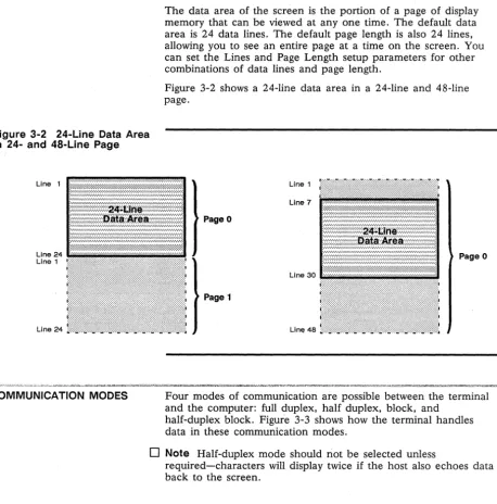
Figure 3-2 24-Line Data Area
in 24- and 48-Line Page
Line 24
Line 1
Line 24
COMMUNICATION MODES
Chapter 3
The data area of the screen is the portion of a page of display
memory that can be viewed at anyone time. The default data
area is 24 data lines. The default page length is also 24 lines,
allowing you to see an entire page at a time on the screen. You
can set the Lines and Page Length setup parameters for other
combinations of data lines and page length.
Figure 3-2 shows a 24-line data area in a 24-line and 48-line
page.
Page 0
Page 0
Page 1
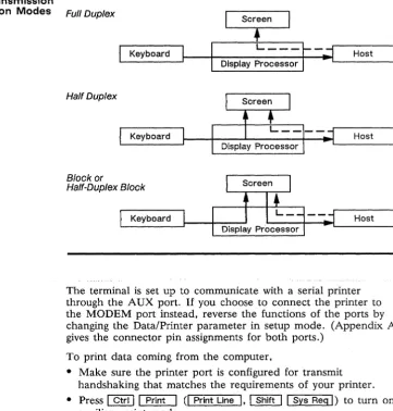
Four modes of communication are possible between the terminal
and the computer: full duplex, half duplex, block, and
half-duplex block. Figure 3-3 shows how the terminal handles
data in these communication modes.
o
Note
Half-duplex mode should not be selected unless
Operating the Terminal
3-3
Figure 3-3 Data Transmission
in the Communication Modes Full Duplex
Screen
PRINTING
Keyboard
Half Duplex
Keyboard
Block or
Half-Duplex Block
•
L _ _ _ ~_~Host
Host
Keyboard Host
~~~~~j----t~DNi:sP~I~ay Pro~c:e:s:so~r~--~L-~~~~
The terminal is set up to communicate with a serial printer
through the A UX port.
Ifyou choose to connect the printer to
the MODEM port instead, reverse the functions of the ports by
changing the Data/Printer parameter in setup mode. (Appendix A
gives the connector pin assignments for both ports.)
To print data coming from the computer,
• Make sure the printer port is configured for transmit
handshaking that matches the requirements of your printer.
• Press
I
CtrlI I
PrintI (I
Print LineI, I
ShiftI I
Sys RegI)
to turn on
auxiliary print mode.
To print a page of data when you have a serial printer connected
directly to the terminal,
3-4
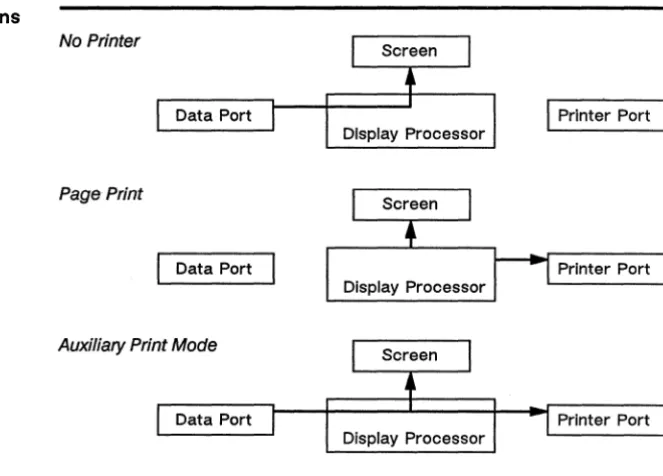
Figure 3-4 Communications
Through the Printer Port
Chapter 3
• Press
I
PrintI (I
PrtScI, I
Print ScreenI)
to send the formatted
page to the printer.
o
Note
Because data is sent from home through the cursor
position, the cursor must be at the bottom of the page if the
entire page is to print.
• When you're finished printing, press
I
ShiftII
BreakI (I
BlockI)
again to take the terminal out of block mode.
Figure 3-4 shows how the terminal handles data through the
printer port.
• Caution
Do not enter data at the keyboard during print
operations. Keyboard data will be sent to the computer and/or the
screen as usual (see Figure 3-3) and,
ifechoed by the computer,
can become mixed with data going to or from the printer port.
No Printer
I
Printer Port Data PortDisplay Processor
Page Print
Data Port Printer Port
Auxiliary Print Mode
Figure 3-4 Communications Through the Printer Port, Continued
Operating the Terminal
Transparent Print Mode
Data Port
Bidirectional Mode
Data Port
AUX Receive Mode
Data Port
3-5
Screen
Printer Port Display Processor
Screen
Printer Port
Screen
Display Processor
INTRODUCING WYSEWORKS
BASIC WYSEWORKS CONTROLS
WyseWorks
WyseWorks is a set of four desktop accessories:
• A calculator with a paper tape feature that displays and prints
the results of your calculations
• An alarm clock with two alarm settings and reminder messages
• A calendar that displays three months at a glance
• An ASCII table displaying numerical equivalents and monitor
mode symbols for 128 U.S. ASCII characters
You have access to these accessories at any time except when
the terminal is in setup mode. They are displayed on the top
eight lines of the screen, which temporarily defaults to 80
columns. (Overlaid data and the previous screen width are
restored when you exit WyseWorks.)
Press @illl Caps
LockI
to display the WyseWorks entry screen,
where the fields at the bottom of the screen display the name of
each accessory. Follow these steps:
1 To select an accessory, press the indicated function key. The
accessory will appear in the box at the top of the screen.
2 After you've selected an accessory, follow the instructions on
the screen, referring to the explanations in this chapter.
3 When you're ready to leave an accessory,
- Press
I
Ctrlll Caps
LockI
to exit WyseWorks
4-2
CALCULATOR
Calculator Display
Chapter 4
The calculator works very much like a handheld calculator, with
the keyboard acting as the numeric keypad and the screen
displaying the results of your calculations. A paper tape feature
allows you to display five entries at a time and send them to a
printer connected directly to the terminal.
In the box at the top of the screen the display shows
• A keypad that highlights the numbers and functions as you
enter them on the keyboard
• Five memory locations, with a pointer «m) indicating the
active memory where you can store and recall your current
calculation.
The two fields at the bottom of the screen indicate the function
keys that turn the paper tape feature's display and print
functions on or off. The current status (on or off) is shown in
each field.
• When the tape is
on,
each keyboard entry appears at the left
of the calculator display (see Figure 4-1), scrolling up like a
paper tape. When more than five entries are made, the top
entry scrolls off.
• When the printer is also
on,
each successive bottom line of the
tape is sent to' the port configured as the printer port.
Figure 4-1 shows the calculator's display of the calculation
[ (7+
5) x 12]+
4when the tape display is on.
Figure 4-1 Sample Calculator
Display
Tape Display
Calculator Operations
WyseWorks
Sign
Change Clear
Memory Displays
Store Recall
Result of Current Calculation
Keypad Display
The calculator has an absolute numerical range of
±0.001 to
9,999,999,999.9999.
Paper Tape Feature
Both the tape display and printer are off when you turn on the
terminal and first enter WyseWorks. To turn on the tape display,
press [£I].
To activate the printer, press
em.
Observe the
following precautions:
• Turn on the tape before starting your calculation-turning it on
clears existing entries.
• Don't turn the printer on unless the tape display is also on and
a printer is connected directly to the terminal.
Until you turn off the terminal, the status of the tape display and
printer will remain as you last set them.
Keyboard Controls
Table
4-1
summarizes the calculator operations that you can
perform from the keyboard and lists the keys that control them.
The corresponding keypad display is highlighted as you make
each entry at the keyboard.
4-4
Chapter 4
Table 4-1 Calculator Controls
Keyboard StyleWY-60 Enhanced Display
Operation ASCII IBM 316X ATl PCl Highlight
Tape onloff
IE!]
IE!]
IE!]
IE!]
Fl=TAPE ON Fl=TAPE OFFPrinter port onloff
em
em
em
em
F2=PRINTER ON F2=PRINTER OFFEnter number
[QJ -
[2]2[QJ -
[2]2[QJ -
[2]2[QJ -
[2]2 0-9Enter decimal point
[]2
[]2 []2 []2Add [J2 [J2
[±]2
[±]2
+Subtract G2 ·G2 G2 G2
Multiply
I
RepllI
SelectI
c::J2 c::J2*
DivideI
Clr LineI
I
Send LineI
Scroll LockI
[2]2 IProduce result
I
EnterI
I
EnterI
I
Sys ReqI
I
Enter 12Reciprocal
I
Clr LineI
I
Send LineI
Scroll LockI
[2]2 Iand
I
EnterI
andI
EnterI
andI
Sys ReqI
andI
Enter 12 SquareI
ReplI
I
SelectI
c::J2 c::J2*
and
I
EnterI
andI
EnterI
andI
S}!S ReqI
andI
Enter 12 Select memory ~ or[!]
IT] ormI
EnterI
IT]or[TI <mStore displayed number in
I
Ins CharI
~
I
EscI
I
HomeI
STOmemory (at pointer)
Recall memory contents Del Char
I
I
pagelI
Num LockI
I
Page UpI
RCL(from memory at pointer)
Clear entry [Q!!J
I
ClearI
[33I
Num LockI
C/EClear calculator [Q!!J4
I
Clear 14 [33t4I
Num Lock 14 C/EClear memory (at pointer)
I
ShiftI
[Q!!JI
ShiftI I
ClearI I
Shift 1[33I
ShiftI
C/EI
Num LockI
Clear all memoriesI
ShiftI
[Q!!J4I
ShiftI I
Clear 14I
ShiftI
[33,4I
ShiftI
C/EI
Num Lock 14 Change sign of displayedI
SendI
I
Erase EOFI
[SJ
I
Page DownI
+1-number
1. On these keyboards, the keys perform the indicated functions regardless of NUM LOCK status.
. 2. These keys are found on the numeric keypad .
3. Backspace key.
ALARM CLOCK
Alarm Clock Display
Setting the Alarm
WyseWorks
Error Messages
If
your calculation exceeds 14 digits or if a number has been
divided by zero, an error message appears on the top line of the
screen (the status line):
**Number too large**
**Division by zero**
If
this happens, clear the calculation and recalculate.
In the alarm clock accessory you can set two alarm times and
enter two 20-character reminder messages. At the set
~ime,the
alarm sounds for 30 seconds, and any reminder message is
simultaneously displayed on the status line.
D
NoteThe alarm sounds only during normal terminal operation,
not while the terminal is in WyseWorks or setup mode.
The alarm clock display shows
4-5
• The current time according to the terminal's clock (default
8:00 a.m.)
• Two alarm setting lines-Alarm 1 and Alarm 2-each with a
time field (default 12:00 a.m.), a 20-character message field,
and an on/off indicator field
Position the cursor in the appropriate fields:
1 Press the cursor keys or
~or
1 Backspace 1to go from field
to field. Pressing
1
Return 1(I
EnterI)
moves the cursor to the
start of a line.
2 To reset the terminal's clock, enter the current time (12-hour
format, including a.m. or p.m.) in the time field.
3 Enter the desired alarm time in the Alarm 1 or Alarm 2 time
field and the desired message in the message field.
4 In the on/off indicator field, press any key to set the alarm
bell to
on.
4-6
Turning Off the Alarm
CALENDAR
Calendar Controls
ASCII TABLE
ASCII Table Controls
Chapter 4
To turn off the alarm, press
I
SetupI
(I
ResetI ,
I
Sys RegI ,
I
SelectI).
Before you can resume normal operation or reenter WyseWorks
you must press
I
SetupI
(I
ResetI,
I
Sys RegI,
I
SelectI)
again to
clear the message displayed on the status line.
The calendar displays three months at a time, defaulting to the
factory setting when the terminal is turned on.
(If
more than five
lines are required to include all the days, the leftover days of the
month won't appear.)
To display other months in the year, press
•
~
(I-I)
for earlier months
· rn
(I-I)
for later months
To display the same months in another year, press
• rn (rn)
for earlier years
• [A]
([f])for later years
The two-page ASCII table displays the hexadecimal codes for the
U.S. ASCII table (64 codes per page), showing the monitor mode
symbols for the current terminal personality.
The status line displays the corresponding ASCII character or
control code, as well as binary, decimal, and octal equivalents,
for the hexadecimal code that's highlighted in the table.
Appendix
A
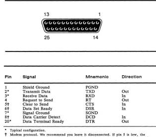
Figure A-1 MODEM and AUX
Port Pin Numbers
Table A-1 MODEM Port
Connector Pin Assignments
(DTE)
Connector Pin Assignments
Figure A-l shows the MODEM and AUX port pin numbers.
13
25
14Pin Signal Mnemonic Direction
1 Shield Ground PGND
2* Transmit Data TXD Out
3* Receive Data RXD In
4 Request to Send RT Out
5t
Clear to Send CTS In6t
Data Set Ready DSR In7* Signal Ground SGND
8t
Data Carrier Detect DCD In20* Data Terminal Ready DTR Out
• Typical configuration.
A-2
Table A-2 Typical Modem
Pin Assignments
Appendix A
Terminal (DTE)
1 2
3
7 20
Hayes Smart modem 1200 (DeE)
1 2
3 7
20
We recommend that pins 6 and 8 be disconnected, as they are
modem protocols that may lock up the terminal.
D
Note
Hayes Smartmodem
1200
front panel switch settings are
DUDUDDUD.
Table A-3 AUX Port Connector
PinPin Assignments (DCE)
Signal Mnemonic Direction
1 2* 3*
6
7* 20*
Shield Ground Transmit Data Receive Data Data Set Ready Signal Ground Data Terminal Ready
• Typical configuration.
PGND TXD RXD DSR SGND DTR
In Out Out
Appendix
B
Key Codes
This appendix lists the key codes for the terminal's ASCII
personalities. See Appendix F for the terminal's ANSI personality
key codes.
Tables B-1 through B-4 list ASCII codes for each of the four
keyboards available for the terminal.
• The tables include codes for all ASCII personalities
except
PC
Term, in which the keys send scan codes, not ASCII
characters.
• Codes are given for editing and special keys only.
Alphanumeric keys send the standard ASCII codes (see
WyseWorks ASCII Table).
o
Note
NUM LOCK must be off for editing and special key codes
to be sent from the numeric keypad on the AT-style and
Enhanced PC-style keyboards.
Table B-S summarizes the hexadecimal values of the scan codes
sent by the keys on all keyboards when the terminal is in the PC
Term personality-each key sends one scan code when pressed
(the
down
code) and another code when released (the
up
code)
• The table gives the codes for the editing and special keys only.
• Scan codes for the alphanumeric and function keys are shown
on the AT-style and Enhanced PC-style keyboard illustrations.
Only the down codes are shown. The up code is the same as
the down code except the high bit is set (bit 7 is active). (The
same codes are sent by the alphanumeric and function keys on
the other keyboards when the terminal is in the PC Term
personality. )
B-2 Appendix B
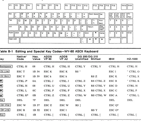
Figure 8-1 WY-60 ASCII Keyboard
Table 8-1 Editing and Special Key Codes-WY-60 ASCII Keyboard
Natlve1 Hex. ADDS ADDS DG 200/DG 210
Key Code Value VP 60 VPA2 Unshifted Shifted IBM HZ-1S00
I
BackspaceI
CTRLH 08 CTRLH CTRLH CTRLY CTRLY CTRL H CTRLHClr Line
I
ESC T IB 54 ESC K ESC K RS ~ ESC I - CTRL 0I
Clr ScrnI
ESC Y IB 59 ESC k ESC k RS Z ESC K - CTRL X[!]
CTRL J2 OA CTRLJ CTRL J CTRLZ RS CTRL Z ESC B - CTRL KBJ
CTRLH 08 CTRLU CTRL U CTRLY RS CTRL Y ESC D CTRL H~
CTRLL OC CTRL F CTRL F CTRLX RS CTRL X ESC C CTRL Prn
CTRL K3 OB CTRLZ CTRLZ CTRLW RS CTRLW ESC A - CTRL L@ill
DEL 7F DEL DEL DEL DEL DELDel Char
I
ESCW 18 57 ESC E ESCW RS1
ESC Q4Del Line
I
ESC R IB 52 ESC 1 ESC I RS Y ESC O'I
EscI
CTRL [ IB CTRL [ CTRL [ CTRL [ CTRL [ CTRL [ CTRL [1. These codes also recognized in WY-50+, ADM 31, and TeleVideo 910/920/9251950/955 personalities. Unless otherwise noted, shifted keys send the same code as unshifted.
2. CTRL V if the terminal is in TeleVideo 925, 950, or 955 personality.
3. Shifted key sends ESC j in TeleVideo 925, 950, or 955 personality. ~
Key Codes
8-3
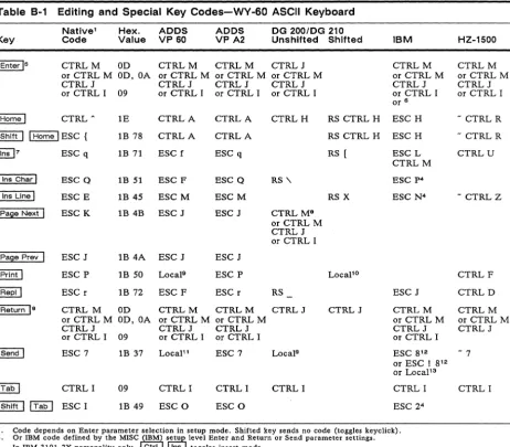
Table 8-1 Editing and Special Key Codes-WY-60 ASCII Keyboard
Native1 Hex. ADDS ADDS DG 200IDG 210
Key Code Value VP 60 VP A2 Unshifted Shifted IBM HZ-1500
I
Enter 15 CTRLM OD CTRLM CTRLM CTRLJ CTRLM CTRLMor CTRL M OD, OA or CTRL M or CTRL M or CTRL M or CTRL M or CTRL M
CTRLJ CTRLJ CTRLJ CTRLJ CTRLJ CTRLJ
or CTRL I 09 or CTRL I or CTRL I or CTRL I or CTRL I or CTRL I
or 6
I
HomeI
CTRL ~ 1E CTRLA CTRLA CTRLH RS CTRL H ESC H - CTRL RI
ShiftI I
HomeI
ESC { 1B 78 CTRLA CTRLA RS CTRL H ESC H - CTRL R~7 ESC q 1B 71 ESC f ESC q RS [ ESC L CTRLU
CTRLM
Ins Char
I
ESC Q 1B 51 ESC F ESC Q RS '\ ESC p4Ins Line I ESC E 1B 45 ESCM ESCM RS X ESC N4 - CTRL Z
I Palle Next I ESC K 1B 4B ESC J ESC J CTRL M8
or CTRL M CTRLJ or CTRL I
I Page Prey ESC J 1B 4A ESC J ESC J
I Print
I
ESC P 1B 50 Locals ESC P Locapo CTRLFI Repl I ESC r 1B 72 ESC F ESC r RS ESC J CTRLD
I
Return1
8 CTRL M OD CTRLM CTRLM CTRLJ CTRLJ CTRLM CTRLMor CTRL M OD,OA or CTRL M or CTRL M or CTRL M or CTRL M
CTRLJ CTRLJ CTRLJ CTRLJ CTRLJ
or CTRL I 09 or CTRL I or CTRL I or CTRL I
I Send
I
ESC 7 1B 37 LocaP1 ESC 7 Local9 ESC 8 12 - 7or ESC! 8 12 or LocaP3
I
TabI
CTRL I 09 CTRL I CTRLI CTRL I CTRL I CTRL II Shift I I Tab
I
ESC I 1B 49 ESC 0 ESC 0 ESC 24S. Code depends on Enter parameter selection in setup mode. Shifted key sends no code (toggles keyclick).
6. Or IBM code defined by the MISC I(IBM)I j"tu
J
level Enter and Return or Send parameter settings.7. In IBM 3101-2X personality only, Ctrl Ins toggles insert mode.
8. Code depends on Return parameter selection in setup mode.
9. Prints unprotected.
10. Prints all.
11. Sends data to computer.
12. IBM 3161 personality only; code depends on Send parameter selection in setup mode. Line turnaround character is also sent.
B-4 Appendix B
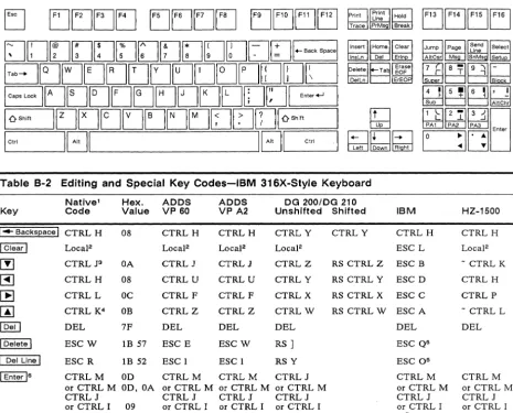
Figure B-2
IBM
316X-Style KeyboardEJ
EJEJEJEJ EJEJEJEJ
EJEJEJ[:]
[]D(][](]~[][][8D[]u[;]
+-Back SpaceE:J[]EJEJ[]~[]tJ[JEJrJ[J[]D
EtJE][][][]E]tJDDD[]1
Ente,~
I
EJEJEJEJ
Jump 1 pag; I sL,end ,ne Select AltCsr Ms SnMs Setu
~~~n
~t=:j~~
f41lf5!l~n
~cJt=J~
IOShi!t I [ ] [ ][][][][]EJtJ[][JI
°
Shift 1ICt,;
181
IEJI
Ct,;1
rn
118~f33lB
t]Ej
tgJwtE6fj
I:J~oJI:J
10
:11'
~I
Ente'Table B-2 Editing and Special Key Codes-IBM 316X-Style Keyboard
Native1 Hex. ADDS ADDS DG 200lOG 210
Key Code Value VP 60 VP A2 Un shifted Shifted IBM HZ-1500
I .... Backspace 1 CTRLH 08 CTRL H CTRLH CTRLY CTRLY CTRL H CTRL H
1 Clear I Local2 LocaF Local2 LocaJ2 ESC L LocaJ2
[!]
CTRL J3 OA CTRL J CTRLJ CTRLZ RS CTRL Z ESC B - CTRL K~
CTRLH 08 CTRL U CTRL U CTRLY RS CTRL Y ESC D CTRL H[B
CTRL L OC CTRL F CTRLF CTRLX RS CTRL X ESC C CTRL P~
CTRL K4 OB CTRLZ CTRLZ CTRLW RS CTRL W ESCA - CTRL L@ill
DEL 7F DEL DEL DEL DEL DELI
DeleteI
ESCW IB 57 ESC E ESCW RS1
ESC Q5I
Del LineI
ESC R IB 52 ESC I ESC I RSY ESC 05I
EnterIs
CTRLM OD CTRLM CTRLM CTRLJ CTRLM CTRLMor CTRL M OD,OA or CTRL M or CTRL M or CTRL M or CTRL M or CTRL M
CTRLJ CTRLJ CTRLJ CTRLJ CTRLJ CTRLJ
or CTRL I 09 or CTRL I or CTRL I or CTRL I or CTRL I or CTRL I
or7
1. These codes are also recognized in WY-50+, ADM 31, and TeleVideo 910/920/9251950/955 personalities. Unless otherwise noted, shifted keys send the same code as unshifted.
2. Clears page to nulls, turning off protect and write-protect modes. 3. CTRL V if the terminal is in TeleVideo 925,950, or 955 personality. 4. Shifted key sends ESC j in TeleVideo 925, 950, or 955 personality. 5. IBM 3101-2X and IBM 3161 personalities only.
Key Codes
8-5
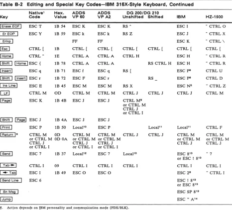
Table B-2 Editing and Special Key Codes-IBM 316X-Style Keyboard, Continued
Native' Hex. ADDS ADDS DG 200/DG 210
Key Code Value VP 60 VPA2 Unshlfted Shifted IBM HZ-1500
I Erase EOF I ESCT IB 54 ESC K ESC K RS A ESC I - CTRL 0
I Er EOP ESC Y IB 59 ESC k ESC k RSZ ESC J - CTRLX
~
FF FF ESC K - CTRL \I Esc I CTRL [ 1B CTRL [ CTRL [ CTRL [ CTRL [ CTRL [ CTRL [
I Home I CTRLA IE CTRLA CTRLA CTRLH ESC H - CTRL R
I Shift I I Home I ESC { IB 78 CTRLA CTRLA RS CTRL H ESC H - CTRL R
I Insert I ESC q IB 71 ESC f ESC q RS [ ESC p8 CTRLU
I Shift I I Insert I ESC r IB 72 ESC F ESC r RS ESC p8 CTRLD
I Ins Line I ESC E IB 45 ESCM ESCM RS X ESC N5 - CTRLZ
[bEJ
CTRLM OD CTRLM CTRLM CTRLJ CTRLJ CTRLJ CTRLMI Pagel ESC K IB 4B ESC J ESC J CTRL M9
or CTRL M CTRLJ or CTRL I
I Shift I I Page I ESC J IB 4A ESC J ESC J
I Print I ESC P IB 50 Locapo ESC P LocaP' LocaP' CTRLF
I Return 19 CTRLM OD CTRLM CTRLM CTRLJ CTRLJ CTRLM CTRLM
or CTRL M OD OA or CTRL M or CTRL M or CTRL M or CTRL M
CTRLJ CTRLJ CTRLJ CTRLJ CTRLJ
or CTRL I or CTRL I or CTRL I
I Send I ESC 7 IB 37 LocaP2 ESC 7 Locapo ESC 8'3 - 7
or ESC! 8'3
I Tab-I CTRLI 09 CTRLI CTRL I CTRL I CTRLI CTRL I
I-Tabl ESC I IB 49 ESC 0 ESC 0 ESC 29 - CTRL I
I Send Line ESC 6 ESC I 8'3
or ESC 8'3
I Sn Ms§! ! ESC SP 8'3
!Jump! ESC" A'4
8. Action depends on IBM personality and communication mode (FDX/BLK). 9. Action depends on Return parameter selection in setup mode.
10. Prints unprotected.
11. Prints all.
12. Sends data to computer.
13. IBM 3161 personality only; code depends on Send parameter selection in setup mode.
8-6
Appendix 8
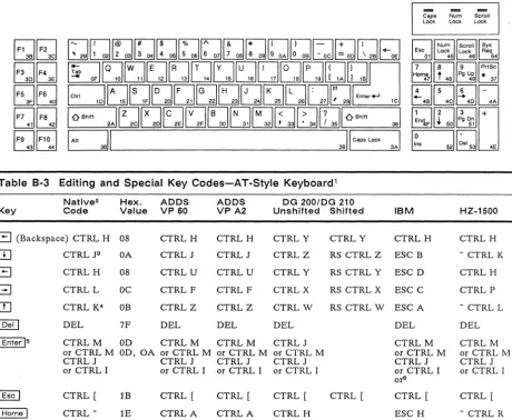
Figure B-3 AT-Style Keyboard
r;,Ir;;l
UL12l
r;;lr;!
L22lClli
1;0r;;1
L2clU
r;;Ir;;;!
U~
IF9
JF1~1
~
Esc 1 Num Lock 1 Scroll [5JYS Lock Req01
45 46 54
f7lf8lfT.l[PriSc]
~~~U
I! 4BIUI-! 4DII- 4AI
[hJ[QI~ ~~'D
1
~S
5211
~.I
531 4ETable B-3 Editing and Special Key Codes-AT-Style Keyboard
1Key
Natlve2
Code
Hex. ADDS
Value VP 60 ADDS VPA2 Unshifted Shifted DG 200/DG 210 IBM HZ-1500
G
(Backspace) CTRL H 08 CTRLHCTRLJ CTRLU CTRLF CTRLZ CTRLH CTRLJ CTRLU CTRLF CTRLZ DEL CTRLM CTRLY CTRLZ CTRLY CTRLX CTRLW DEL CTRLJ
CTRLY CTRLH CTRL H
1. 2. 3. 4. 5. 6.
CTRL J3
CTRLH
CTRLL
CTRL K4 DEL
CTRLM or CTRL M CTRLJ or CTRL I
CTRL [
CTRLA
OA
08
DC
DB
7F DEL
OD CTRLM
OD, OA or CTRL M
IB
IE
CTRLJ or CTRL I
CTRL [
CTRLA
or CTRL M CTRLJ or CTRL I
CTRL [
CTRLA
or CTRL M CTRLJ or CTRL I
CTRL [
CTRLH
RS CTRL Z ESC B
RS CTRL Y ESC D
RS CTRL X ESC C
RS CTRL W ESC A
CTRL [
DEL
CTRLM or CTRL M CTRLJ or CTRL I or6
CTRL [
ESC H
- CTRL K
CTRLH
CTRLP
- CTRL L
DEL
CTRLM or CTRL M CTRLJ or CTRL I
CTRL [
- CTRL R
Codes shown on' keyboard layout are alphanumeric and function key scan codes sent in PC Term personality (the high bit is set when the key is released). See Table B-5 for scan codes sent by the editing and special keys in this personality.
These codes are also recognized in WY-50+, ADM 31, and TeleVideo 910/920/9251950/955 personalities. Unless otherwise noted, shifted keys send the same code as unshifted.
CTRL V if the terminal is in TeleVideo 925, 950, or 955 personality. Shifted key sends ESC j in TeleVideo 925, 950, or 955 personality.
Key Codes
Table 8-3 Editing and Special Key Codes-AT-Style Keyboard1, Continued
Native2 Hex. ADDS ADDS DG 200/DG 210
Key Code Value VP 60 VP A2 Unshifted Shifted IBM HZ-1S00
IE]
ESC r 1B 72 ESC F ESC r RS ESC J CTRL D~IE] ESC q 1B 71 ESC f ESC q RS [ ESC p7 CTRL U
I
PgDnI
ESC K 1B 4B ESC J ESC J CTRL J8or CTRL I
I
PgUpI
ESC J IB 4A ESC J ESC J CTRL J8or CTRL M
I
PrtSeI
ESC P 1B 50 Locals ESC P Local'°
ESC W7 CTRL FI Tab--I
CTRL I 09 CTRL I CTRL I CTRL I CTRL I CTRL II
ShiftI I Tab--I
ESC I 1B 49 ESC 0 ESC 0 ESC 277. Action depends on IBM personality and communication mode (FDX/BLK). No code sent in IBM 3101-1X personality. 8. Code depends on Return parameter setting in setup mode.
9. Prints unprotected. 10. Prints all.
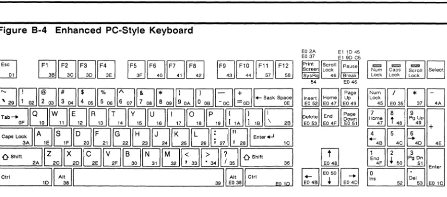
Figure 8-4 Enhanced PC-Style Keyboard
R
~
fF1lfF2lrF3lrF4l
~WWW
fFsIfF6l[F7lfFsI
UU~~Lill
fF9l1F1Ol[F11lrml
~LdUU
E02A El1D45
EO 37 El 90 C5
I E!4SI
ClfEoSoll-:l
~W~
~~C~51:a
351L:J1-
4J
rI:1
Ifl
,
~D
t:::]J~~
+1!4B
IUI!4D I 4E
fClffll;g
Dnl
L:kJ~ 51
1
0I@
Enter Ins Del8-8
Appendix 8
Table 8-4 Editing and Special Key Codes-Enhanced PC-Style Keyboard
1 Native2 Hex. ADDS ADDS DG 200/DG 210Key Code Value VP 60 VPA2 Unshifted Shifted IBM HZ-1S00
1-Backsl2acel CTRLH 08 CTRLH CTRLH CTRLY CTRLY CTRLH CTRLH
[[]
CTRL J3 OA CTRLJ CTRLJ CTRLZ RS CTRL Z ESC B - CTRL KG
CTRLH 08 CTRLU CTRLU CTRLY RS CTRL Y ESC D CTRLHG
CTRLL DC CTRLF CTRLF CTRLX RS CTRL X ESC C CTRLP[!]
CTRL K4 DB CTRLZ CTRLZ CTRLW RS CTRLW ESC A - CTRL L@illkpd DEL 7F DEL DEL DEL DEL DEL
1 Delete 1 ESCW IB 57 ESC E ESCW RS
1
ESC Q5 CTRLB1 Shift "Delete I ESC R IB 52 ESC 1 ESC 1 RS Y ESC 05 - CTRL S 1 End Ikpd ESC T IB 54 ESCK ESCK RS A ESC I - CTRL 0
1 End I ESC T IB 54 ESC K ESC K RS A ESC I - CTRL 0
1 Shift 1 1 End 1 ESC Y IB 59 ESCk ESCk RS Z ESC K - CTRL X
1 Enter IkpciB CTRLM OD CTRLM CTRLM CTRLJ CTRLM CTRLM
or CTRL M OD,OA or CTRL J or CTRL M or CTRL M or CTRL M
CTRLJ CTRLM CTRLJ CTRLJ CTRLJ
or CTRL I 09 or CTRL I or CTRL I or CTRL I or CTRL I
or7
I Enter Ie CTRLM OD CTRLM CTRLM CTRLJ CTRLM CTRLM
or CTRL M OD, OA or CTRL M or CTRL M or CTRL M or CTRL M or CTRL M
CTRLJ CTRLJ CTRLJ CTRLJ CTRLJ CTRLJ
or CTRL I 09 or CTRL I or CTRL I or CTRL I or7 or CTRL I
1 Esc I CTRL [ IB CTRL [ CTRL [ CTRL [ CTRL [ CTRL [ CTRL [
I Home Ikpd CTRL A IE CTRLA CTRLA CTRLH ESC H - CTRL R
1 Shift II Home Ikpd ESC { IB 7B CTRLA CTRLA RS CTRL H ESC H
1 Home I CTRL A IE CTRLA CTRLA CTRLH ESC H - CTRL R
1 Shift 1 1 Home 1 ESC { IB 7B CTRLA CTRLA RS CTRL H ESC H - CTRL R
1. Codes shown on keyboard layout are alphanumeric and function key scan codes sent in PC Term personality (the high bit is set when 2.
the key is released). See Table B-5 for scan codes sent by the editing and special keys in this personality.
These codes are also recognized in WY-50+, ADM 31, and TeleVideo 910/920/9251950/955 personalities. Unless otherwise noted, shifted keys send the same code as unshifted.
3. CTRL V if the terminal is in TeleVideo 925, 950, or 955 personality. 4. Shifted key sends ESC j in TeleVideo 925, 950, or 955 personality. 5. Action depends on IBM personality and communication mode (FDX/BLK).
6. Code depends on Enter parameter selection in setup mode. Shifted key sends no code (toggles key click) .
7. Or IBM code defined by the MISC (IBM) setup level Enter and Return or Send parameter settings.