Real-Time Adaptive Foreground/Background
Segmentation
Darren E. Butler
Information Security Institute, Queensland University of Technology, Brisbane QLD 4001, Australia Email:[email protected]
V. Michael Bove Jr.
Media Laboratory, Massachusetts Institute of Technology, Cambridge, MA 02139, USA Email:[email protected]
Sridha Sridharan
Information Security Institute, Queensland University of Technology, Brisbane QLD 4001, Australia Email:[email protected]
Received 2 January 2004; Revised 8 November 2004
The automatic analysis of digital video scenes often requires the segmentation of moving objects from a static background. His-torically, algorithms developed for this purpose have been restricted to small frame sizes, low frame rates, or offline processing. The simplest approach involves subtracting the current frame from the known background. However, as the background is rarely known beforehand, the key is how to learn and model it. This paper proposes a new algorithm that represents each pixel in the frame by a group of clusters. The clusters are sorted in order of the likelihood that they model the background and are adapted to deal with background and lighting variations. Incoming pixels are matched against the corresponding cluster group and are classified according to whether the matching cluster is considered part of the background. The algorithm has been qualitatively and quantitatively evaluated against three other well-known techniques. It demonstrated equal or better segmentation and proved capable of processing 320×240 PAL video at full frame rate using only 35%–40% of a 1.8 GHz Pentium 4 computer.
Keywords and phrases:video segmentation, background segmentation, real-time video processing.
1. INTRODUCTION
As humans we possess an innate ability to decompose ar-bitrary scenes and with only a casual glance we can recog-nise a multitude of shapes, shades, and textures. In contrast, computers require enormous amounts of processing power and frequently fail if, for instance, the sun hides behind a cloud. As a consequence, practical solutions often rely upon domain-specific knowledge to make the problem tractable. For instance, if we know that we are compressing a head-and-shoulders sequence, then we also know that most of the in-formation pertains to the participant. Hence, we can employ differential bit allocation and encode their facial expressions and gestures with a higher quality than the background. Al-ternatively, we could try to fit a parameterised model to the participant [1] or derive one from them [2] and thereby ob-tain even greater compression. In either case, the first step is to segment the participant from the background and we can exploit their movements to help us do so.
Motion is a particularly important cue for computer vi-sion. Indeed, for many applications, the simple fact that
something is moving makes it of interest and anything else can be ignored. In such cases, it is common for moving jects to be referred to as the foreground and stationary ob-jects as the background. A classic example from the litera-ture is automatic traffic flow analysis [3] in which motion is used to differentiate between vehicles (the foreground) and the roadway (the background). Higher-level processing could then be employed to categorise the vehicles as cars, mo-torcycles, buses, or trucks. Such a system might be used for determining patterns of traffic flow, or it could be adapted to automatically identify traffic law violations. Other appli-cations where motion is important include gesture tracking [4,5], person tracking [6,7,8], model-based video coding [9,10,11], and content-based video retrieval [12]. In prac-tice, the need to segment moving objects from a static back-ground is so common, it has spawned a nich`e area of research where it is known as background subtraction, background segmentation, or background modelling.
involves calculating an average background frame whilst no moving objects are present. Subsequently, when objects en-ter the scene, they will cause the current frame to diverge from the background frame and their presence can be eas-ily detected by thresholding the difference between them [13]. However, any background or illumination change will severely and indefinitely degrade the accuracy of the algo-rithm. Therefore, practical implementations must continu-ously update the background frame to incorporate any per-manent scene changes. Furthermore, assuming that the back-ground is perfectly stationary is also flawed. For instance, a tree branch waving in the wind moves but is typically not im-portant and so should be incorporated into the background model. We define pseudostationary backgrounds as having constituent objects that are either motionless or that undergo small repetitive motions. A single average background frame is clearly incapable of correctly modelling pseudostationary backgrounds. In practice, the stationarity assumption is of-ten retained and subsequent processing is used to eliminate errors.
Background segmentation is but one component of a po-tentially very complex computer vision system. Therefore, in addition to being accurate, a successful technique must con-sume as few processor cycles and as little memory as possi-ble. An algorithm that segments perfectly but is very compu-tationally complex is useless because insufficient processing power will remain to do anything useful with its results.
Seed and Houghton conducted one of the earliest studies into background subtraction in 1988 [14]. They realised that true background changes tend to occur gradually and hence proposed a number of techniques that refined the back-ground frame accordingly. Of the techniques, the two most promising wererandom updatingandslope limited updating. Random updating replaces background pixels by the corre-sponding pixels in the current frame according to a pseudo-random sequence. As no reference is made to what data the pixels actually contain, errors in the background frame will occur. However, the errors are isolated and can be reduced using conventional morphological operations. In contrast, slope limited updating only adjusts the background frame when it differs substantially from the current frame and even then only by small amounts. Remarkably, given the level of computer technology at the time, they further showed that by using these techniques, it was possible to distinguish be-tween vehicles and the roadway in real time.
More recently, Chien et al. have revisited background subtraction [15]. They surmised that the longer a pixel re-mained roughly constant, the more likely it is that it belongs to the background. Pixels are classified as stationary when the amount by which they change between consecutive frames falls below a threshold. Once a pixel has remained stationary for a sufficient number of frames, it is copied into the back-ground frame.
Although the above algorithms succeed in learning and refining the background frame, none of them is capable of handling pseudostationary backgrounds. Stauffer and Grim-son recognised that these kinds of backgrounds are inher-ently multimodal and hence they developed a technique
which models each pixel by a mixture of Gaussians [16]. In-coming pixels are compared against the corresponding mix-ture in an effort to find a Gaussian that is within 2.5 stan-dard deviations. If such a Gaussian exists, then its mean and variance are refined according to the pixel. However, if no match is found, then the minimum weighted Gaussian is re-placed by a new one with the incoming pixel as its mean and a high initial variance. Gaussians that are matched more fre-quently are nearby often occuring pixels and hence they are more likely to model the background. This algorithm has since been updated to suppress shadows and to improve its learning rate [17].
A less obvious advantage of Stauffer and Grimson’s tech-nique is its ability to rapidly adapt to transient background changes. For example, if an object enters the scene and stops moving, it will eventually be incorporated into the back-ground model. If it then moves again, the system should recognise the original background as corresponding Gaus-sians should still remain in the mixture. However, maintain-ing these mixtures for every pixel is an enormous computa-tional burden and results in low frame rates when compared to the previous approaches. Our algorithm is most similar to that of Stauffer and Grimson but with a substantially lower computational complexity. As we will show, it has the capa-bility of processing 320×240 video in real time on modest hardware.
The remainder of the paper is organised as follows: Section 2 introduces the new background segmentation scheme andSection 3details its implementation, including a few subtle optimisations; the postprocessing algorithm is de-scribed inSection 4;Section 5compares our approach with a few other published techniques and presents some results; some real-world applications that have benefitted from this work are outlined briefly inSection 6; and finally,Section 7 concludes the paper.
2. ALGORITHM
The premise of our approach is that the more often a pixel takes a particular colour, the more likely it is that it belongs to the background. Therefore, at the heart of our algorithm is a very low complexity method for maintaining some limited but important information about the history of each pixel. To do this, we model each pixel by agroupofKclusterswhere each cluster consists of a weightwkand an average pixel value called the centroid ck. A group is necessary because a sin-gle cluster is incapable of modeling the multiple modes that can be present in pseudostationary backgrounds. The size of the group should therefore be set according to the expected modality of the background. Empirically we have found that 3 to 5 clusters per group yield a good balance between accu-racy and computational complexity.
visually pleasing. However, they can cause dramatic colour variations between consecutive frames and hence are intol-erable by almost all computer vision algorithms. Automatic compensation is also not straightforward because different cameras employ different algorithms and only a portion of the frames may be affected. It is possible to compensate for pan, tilt, and other global scene motions but we considered that to be a preprocessing stage which would detract from the key problem we were trying to solve. Furthermore, for many popular applications, like security and videoconferencing, a fixed camera is the norm. The interested reader may like to consult one of the many optical flow algorithms [18,19].
Step1 (cluster matching). The first step in segmenting in-coming frames is to compare each of their pixels against the corresponding cluster group. The goal is to find the match-ing cluster within the group that has the highest weight and hence the clusters aresearched in order of decreasing weight. We define a matching cluster as one which has a Manhattan distance (i.e., sum of absolute differences) between its cen-troid and the incoming pixel below a user prescribed thresh-old,T. A threshold greater than zero is required to tolerate acquisition noise. Higher thresholds should be used with in-expensive cameras, such as webcams, and lower thresholds with more precise 3CCD cameras. Typically we used thresh-olds in the range of [10, 25].
The Manhattan distance is a very useful metric as it is evaluated using only additions and subtractions and can thus be implemented very efficiently. In contrast, assuming RGB video, the squared Euclidean distance metric would require the evaluation of up to three multiplications and two addi-tions for each of the K clusters and for every pixel in the frame. Given the target of 320×240 video and settingK =
5 result in, on average, 576 000 multiplications per frame. Clearly, eliminating these multiplications is very beneficial in terms of reducing the computational complexity of the algo-rithm.
Step2 (adaptation). If, for a given pixel, no matching clus-ter could be found within the group, then the clusclus-ter with the minimum weight is replaced by a new cluster having the pixel as its centroid and a low initial weight (0.01 in our im-plementation). The initial weight corresponds with the likeli-hood that a new cluster belongs to the background. As such, it should be set according to how dynamic the background is expected to be. Rapidly changing backgrounds can have a higher initial weight, whereas it should be decreased if the background is more stationary.
If a matching cluster was found, then the weights ofall
clusters in the cluster group are updated using
w
k=
wk+1 L
1−wk, k=Mk,
wk+1 L
0−wk, k=Mk,
(1)
where Mk is the cluster index of the matching cluster. The parameterLis simply the inverse of the conventional learning
rate,α, and can be used to control how quickly scene changes are incorporated into the background model. Smaller values forLwill result in faster adaptation and larger values result in slower adaptation.
The centroid of the matching cluster must also be ad-justed according to the incoming pixel. Previous approaches have adjusted the centroid based on a fraction of the diff er-ence between the centroid and the incoming pixel. However, doing so results in fractional centroids and inefficient im-plementations. We chose instead to accumulate the error be-tween the incoming pixel and the centroid. When the error term exceedsL−1, the centroid is incremented, and when it is below−L, the centroid is decremented. This is approx-imately equivalent to adjusting the centroid on every frame usingck = ck+ (1/L)(xt−ck) but avoids the need for frac-tional centroids and can be implemented very efficiently as is detailed inSection 3.
Step3 (normalisation). The weight of a cluster corresponds with how many times it has been matched. Hence, it is from these weights that we can infer information about the his-tory of pixel values. If the weight is high, we know that the pixel has often exhibited a colour similar to the centroid, and according to our premise, the cluster is more likely to model the background. Conversely, if the weight is low, the centroid colour has not appeared very often and the clus-ter probably models the foreground. This observation can be formalised by ensuring the weights of the cluster group al-ways total to one. Then the weights represent the proportion of the background accounted for by each cluster and hence can be treated somewhat like probabilities. Consequently, af-ter adaptation, the weights are normalised according to
w
k=wkS , ∀k, whereS=
k
wk. (2)
This is the same as dictating that the cluster group weight vector,w, must always be a unit vector (i.e.,|w| =1).
Step4 (classification). The incoming pixels are classified by summing the weights of all clusters that are weighted higher than the matched cluster. This calculation is simplified by sorting the normalised clusters in order of increasing weight. Sorting the clusters is also necessary for matching then with pixels of the next frame. However, care must be taken to remember the new location of the matched cluster. After sorting, we employ the following trivial calculation:
P=
K−1
k>Mk
wk. (3)
End No Are there more pixels to process? Yes
Classify the incoming pixel as foreground or
background Create a new
cluster from the incoming pixel
to replace the lowest weighted
cluster
Sort the clusters in order of increasing
weight Normalise the cluster
weights so they total to one
Adapt the weights of all clusters in the
group Adapt the centroid of the matched
cluster Yes
No a matchingWas there
cluster? Search for the highest
weighted cluster that matches the incoming
pixel Start
Figure1: The algorithm.
to obtain a binary decision or can be scaled to produce a grayscale alpha map. A pictorial representation of the algo-rithm is given inFigure 1.
3. IMPLEMENTATION
When implementing the algorithm of Section 2, we were conscious of the fact thatYCBCR4:2:2 video (whereCBand CRhave been subsampled horizontally by a factor of 2) is fre-quently used when acquiring live video. Fortunately, it is also trivial to upsample to 4:2:2 the YCBCR 4:2:0 video that is found in popular compression standards like MPEG-2 and H.263. Using YCBCR 4:2:2 video necessitated making mi-nor modifications to the basic algorithm. Clusters are formed with both a luminance centroid and a chrominance centroid. The luminance centroid consists of two adjacent luminance components (Y1,Y2) and the chrominance centroid holds the corresponding chrominance components (CB,CR). Our implementation uses a cluster structure that is similar to that ofAlgorithm 1. The use of two centroids is beneficial as it al-lows the specification of different thresholds for luminance
typedef struct {
/∗The cluster weight.∗/ double weight;
/∗The luminance centroid.∗/ int Y1, Y2;
/∗The chrominance centroid.∗/ int Cb, Cr;
}Cluster;
Algorithm1: The cluster structure.
31 17 9 0
Centroid component Error
· · · · · ·
Figure2: Centroid component bit assignment: [B=9⇔L=512].
and chrominance. Given only a single threshold, it is likely that luminance would dominate the matching process. With this modification, a match is defined to occur only when the Manhattan distance forboththe luminance and chrominance components is below their respective thresholds.
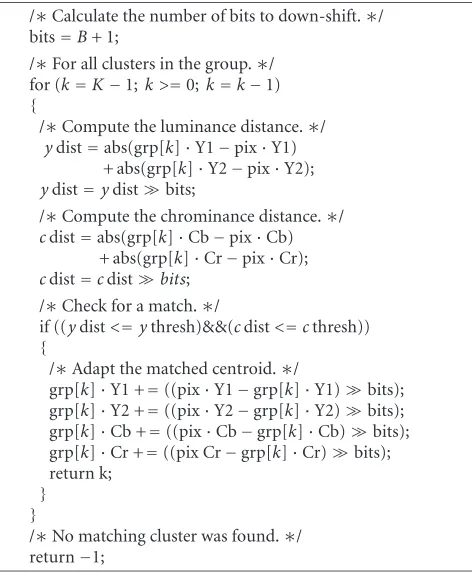
The update equations for the cluster weights are un-changed but we employ a trick to efficiently accumulate the error terms and update the centroids. As aforementioned, the error term lies in the range [−L,L−1]. We can equivalently shift this range to [0, 2×L−1] by the addition ofL. That is, we simply shift the origin of the error term from 0 toL. If we now restrictLto be of the formL=2B, then the entire range of the error term can be specified inB+ 1 bits. Furthermore, adaptation of the centroid now occurs when accumulation of the error term results in overflow or underflow of theB+ 1 bits.
Only 8 bits are required to specify any of the components ofYCBCRvideo. Consequently, if we represent the compo-nents of the centroids (Y1,Y2,CB,CR) by 32 bit integers, then the remaining 24 bits can be used to accumulate the error term. This gives a maximum range forBof [0, 23] or, equiv-alently, L ∈ {1, 2, 4, 8,. . ., 8 388 608}. Recall that L is syn-onomous with the inverse of the learning rate,α. Therefore, by manipulating the number of bits that are used to store L, the user can control the centroid adaptation rate. Accord-ingly, we shift the components of the centroids upwards by B+1 bits and use the lower bits to accumulate the error term, which we initialise to the origin L(seeFigure 2). By virtue of this formulation, when overflow or underflow of the er-ror term occurs, the centroid is neatly adjusted automatically. The elegance of this approach is evident inAlgorithm 2.
A careful examination of the cluster weight update (1) reveals some further optimisations. As shown below, if the weights of a cluster group sum up to one, then after applying the update equation, they will still sum up to one:
k w
k=
k wk+ 1
L
k
Mk−L1 k
wk
=1 +1 L−
1 L =1.
/∗Calculate the number of bits to down-shift.∗/ bits=B+ 1;
/∗For all clusters in the group.∗/ for (k=K−1;k >=0;k=k−1) {
/∗Compute the luminance distance.∗/ ydist=abs(grp[k]·Y1−pix·Y1)
+ abs(grp[k]·Y2−pix·Y2); ydist=ydistbits;
/∗Compute the chrominance distance.∗/ cdist=abs(grp[k]·Cb−pix·Cb)
+ abs(grp[k]·Cr−pix·Cr); cdist=cdistbits;
/∗Check for a match.∗/
if ((ydist<=ythresh)&&(cdist<=cthresh)) {
/∗Adapt the matched centroid.∗/
grp[k]·Y1 +=((pix·Y1−grp[k]·Y1)bits); grp[k]·Y2 +=((pix·Y2−grp[k]·Y2)bits); grp[k]·Cb +=((pix·Cb−grp[k]·Cb)bits); grp[k]·Cr +=((pix Cr−grp[k]·Cr)bits); return k;
} }
/∗No matching cluster was found.∗/ return−1;
Algorithm2: FindMatch (ClusterGroup grp, pixel pix).
Therefore, the cluster weights do not need to be normalised unless a matching cluster could not be found and a new clus-ter had to be created. Furthermore, since the weights of the unmatched clusters are downscaled byexactlythe same fac-tor (i.e.,wk=((L−1)/L)×wk), only matching clusters and newly created clusters will ever be out of order. As the weights of matched clusters will always increase, the sort operation can be improved by only sorting in the direction of the higher weighted clusters.
The core of our algorithm is the cluster matching opera-tion, pseudocode for which is given inAlgorithm 2. The code for adapting the centroid of a matched cluster has been in-corporated into the matching code as a subtle optimisation but this is not mandatory. As described in Section 2, clus-ter matching is based on the Manhattan distance metric be-cause of its simplicity. In fact, it is used so frequently that architecture-dependent optimisations often exist to assist in its calculation. For example, the introduction of the stream-ing SIMD (sstream-ingle instruction multiple data) extensions (SSE) to Intel’s x86 processors added the PSADBW instruction. This instruction calculates the sum of the absolute values of the differences between two packed unsigned byte integer vectors of length eight. That is, it computes the Manhattan distance between two unsigned byte integer vectors in one step. More recently, SSE 2 was introduced which extended this capability and allows the simultaneous computation of two different Manhattan distances using 128 bit registers.
In order to understand our approach fully, it is useful to visualise exactly what is being modeled by the clusters.
As aforementioned, each cluster consists of a centroid (i.e., average pixel value), an error term, and a weight, and within their respective cluster groups they are sorted according to their weight. Furthermore, those that are weighted higher have been matched more frequently and consequently are more likely to represent the background. Therefore, if we form images from the centroids at the same position within their cluster group, then intuitively the images should blend from an image of just the background to an image contain-ing the foreground and outdated or noise-ridden centroids. Figure 3 clearly shows that although the blending is not smooth, the images do transition from the background (k=
3) to a resemblance of the foreground (k=0) and so inspect-ing these images is a good method for verifyinspect-ing the correct-ness of an implementation. Note, however, that this is not the foreground that is returned by the segmenter as foreground pixels are only present in clusters that were just replaced.
4. POSTPROCESSING
No practical background segmenter is omniscient. It does not matter how we have formulated it, we cannot guaran-tee that errors will not occur. In fact, due to the complexity of the problem, the opposite is true: errors are likely. There-fore, it is imperative that steps are taken to detect and elim-inate these errors. If we consider background segmentation to be a two-class problem, then logically two kinds of errors can arise. We define false positives to be regions of the back-ground that have been incorrectly labeled as the foreback-ground. Similarly, false negatives are regions of the foreground that have been labeled as the background. The goal of postpro-cessing is to reduce the number of false postives and false negatives without appreciably degrading the speed of the seg-menter.
As shown in Figure 4, false positives usually resemble pepper noise and are often the result of noise in the cir-cuitry of the camera. They are small (1-2 pixel), erroneously classified regions surrounded by correctly classified back-ground pixels. Fortunately, these kinds of errors can be very easily and very quickly eliminated using the morphological
openoperation. This operation has the additional benefit of smoothing the contour of correctly classified regions without disrupting its shape.
(a) (b)
(c) (d)
Figure3: Centroid images (K=4 andkis the cluster index): (a)k=3; (b)k=2; (c)k=1; and (d)k=0.
(a) (b)
(c)
Figure4: (a) Original; (b) raw segmentation results; and (c) after postprocessing.
remaining regions, which are presumed to be false negatives, can be filled in. Unfortunately, this approach will also fill true holes in the foreground objects, but in practice, this be-haviour is often acceptable.
The postprocessor that we utilise is very simple. First, pixels that are separated by a single gap are joined. Next, the contours of all regions that were classified as foreground are
extracted using facilities of the Open CV library.1If the area
enclosed by the contour is below a user prescribed threshold,
1The Open Source Computer Vision Library is used courtesy of the Intel
then it can be eliminated. Any remaining contours are pre-sumed to border real foreground objects and are retained. If a binary mask is desired instead, then one can be very easily obtained by filling within the contours. An example of the results obtained with this postprocessor is given inFigure 4 and, as shown, it eliminates most, if not all, of the false posi-tives and the false negaposi-tives.
5. EXPERIMENTAL RESULTS
We have evaluated our background segmentation algorithm against our implementations of three other techiques. Whilst every effort was made to ensure their correctness, we can-not guarantee that they are completely free of errors. The first method,VAR, calculates an average frame and a variance frame from a buffer of past frames. Each incoming frame is segmented according to the variance normalised difference between it and the average frame. The algorithm,GMM1, is according to the original work of Stauffer and Grimson [16], whereasGMM2includes the modifications made by Kaew-TraKulPong and Bowden [17]. Finally,NHD,NHD64, and
NHD128correspond to the C, SSE, and SSE2 versions of our algorithm. The inclusion of assembly language versions may seem unfair but this detail is often very important for em-bedded systems designers.
It is unreasonable to expect a user to purchase high-end or specialised equipment just to use a particular background segmenter. Consequently, we only used off-the-shelf com-ponents when evaluating the four algorithms. Our test-bed consisted of a dual 1000 MHz Pentium 3 computer and a 1.8 Ghz Pentium 4 computer both with 512 MB of RAM. The qualitative analysis was completed using both machines. However, only the Pentium 4 computer was used when col-lecting the timing and processor utilisation results.
For reasons outlined earlier, the choice of camera was limited to those with manual white balance and manual gain control. We chose to use two cameras: the low-end Bosch 1153P analog security camera and a more up-market Sony 3CCD camera. However, for the results presented here, the Sony camera was only used for the stability tests. These cameras both provide a composite output and as such, the captured video was subject to luminance and cross-chrominance artifacts, particularly at sharp edges. We found that their effect could be reduced by very slightly defocusing the lens.
5.1. Qualitative analysis
Figure 5visually compares a few manually segmented frames from a five-minute sequence with the results obtained from each of the algorithms. The postprocessor described in Section 4was used with each of the algorithms and although it performs well in general, it is certainly not optimal in ev-ery possible case. Therefore, it is likely that marginally bet-ter results could have been obtained by tweaking it but the improvement would have been minimal and would have de-pended heavily on the acquisition conditions. From the fig-ure, it is clear that our algorithm performs qualitatively as well or better than the other techniques.
5.2. Quantitative analysis
In order to quantify the accuracy of each of the algorithms, we segmented 30 seconds of video manually. The video was designed to contain periods of no motion, periods of slow motion, and periods of very fast motion. The fast motion was problematic as it introduced motion blur and was difficult to accurately and consistently segment by hand. Using the video we were able to calculatefalse acceptance rates(FARs) andfalse rejection rates(FRRs) for each algorithm, where
FAR= # of false positives
# background pixels,
FRR= # of false negatives
# foreground pixels.
(5)
Graphs of the FAR and FRR across the entire sequence are given in Figures 6 and 7, respectively. From Figure 6, we can see that, in terms of false acceptances, our algorithm is significantly more accurate than the simple variance-based segmenter. However, it lags behind both of the remaining two segmenters. This may seem to contradict the results of Figure 5which visually favour our approach but the diff er-ence is only around half a percent and is caused by a slight growth in the border of foreground regions.
The false rejection rates for our algorithm are clearly much lower than any of the other techniques. This can also be seen visually by the lack of holes in the segmentation re-sults ofFigure 5. Every one of the algorithms exhibits an FRR of 100% for at least one frame in the sequence. This occurs when the detected foreground region is so small that it is pre-sumed to be noise and is eliminated by the postprocessor. Hence, a large FRR is also an indication that an object has just entered or is about to exit the scene.
5.3. Computational complexity
As aforementioned, a key issue for any segmentation algo-rithm is its computational complexity. It does not matter how accurately it may be able to segment if in doing so it exhausts all of the processor cycles.Table 1summarises the run-time performance of the four algorithms including the postprocessing stage. For our algorithm, we used a group size of 5 and clearly, given this size, it is approximately two and a half times as complex as the simple variance-based background segmenter. However, its complexity remains well within the capabilities of the hardware and it easily runs in real time (25 fps for PAL video). Furthermore, the segmenta-tion results ofFigure 5significantly favour our approach and our background model is adapted on every frame as opposed to the variance-based segmenter which adapts only once ev-ery three hundred frames (12 seconds).
5.4. Stability testing
(a)
(b)
(c)
(d)
(e)
(f)
Figure 5: Background segmentation results: (a) original; (b) hand-segmented; (c) VAR; (d) GMM1; (e) GMM2; and (f) NHD/NHD64/NHD128.
connecting the Sony camera to a computer and running our algorithm for a period of approximately twenty-four hours. The background was deliberately arranged to be very clut-tered. As is shown inFigure 8, it consisted of nearby objects,
0 100 200 300 400 500 600 700 800 Frame no.
0 0.5 1 1.5 2 2.5 3 3.5 4 4.5 5
FA
R
(%
)
(a)
0 100 200 300 400 500 600 700 800 Frame no.
0 0.5 1 1.5 2 2.5 3 3.5 4 4.5 5
FA
R
(%
)
(b)
0 100 200 300 400 500 600 700 800 Frame no.
0 0.5 1 1.5 2 2.5 3 3.5 4 4.5 5
FA
R
(%
)
(c)
0 100 200 300 400 500 600 700 800 Frame no.
0 0.5 1 1.5 2 2.5 3 3.5 4 4.5 5
FA
R
(%
)
(d)
Figure6: False acceptance rates: (a) VAR; (b) GMM1; (c) GMM2; and (d) NHD/NHD64/NHD128.
the image which fluttered in the wind. In total, over nine hundred thousand (900 000) frames were captured and seg-mented. However, due to storage constraints, it was not pos-sible to save every frame. Unfortunately, this meant that the likelihood of saving an event of interest was very slim. Never-theless,Figure 8contains the segmentation results for frames captured approximately five hours into the test at which time the algorithm is clearly convergent.
6. APPLICATIONS
As aforementioned, accurate background segmentation is vi-tal for many interesting applications. Whilst the previous section has proved that our algorithm performs well under laboratory conditions, this does not guarantee it will do so
in a real-world application. The major difficulty arises with ensuring that enough hardware resources (CPU cycles and memory) remain after segmentation to do something useful with the results. Therefore, in this section, we briefly describe a few developing applications that exploit our technique and present some preliminary results.
6.1. Gesture recognition
0 100 200 300 400 500 600 700 800 Frame no.
0 10 20 30 40 50 60 70 80 90 100
FRR
(%)
(a)
0 100 200 300 400 500 600 700 800 Frame no.
0 10 20 30 40 50 60 70 80 90 100
FRR
(%)
(b)
0 100 200 300 400 500 600 700 800 Frame no.
0 10 20 30 40 50 60 70 80 90 100
FRR
(%)
(c)
0 100 200 300 400 500 600 700 800 Frame no.
0 10 20 30 40 50 60 70 80 90 100
FRR
(%)
(d)
Figure7: False rejection rates: (a) VAR; (b) GMM1; (c) GMM2; and (d) NHD/NHD64/NHD128.
Table1: Algorithm features and performance.
Algorithm Video format User params. Frame rate (fps)
Mem. usage (MB)
CPU usage (%)
VAR Y’CbCr 8 25 13.5 14.4
GMM1 [16] RGB 2 10 25.5 99.9
GMM2 [17] RGB 2 22, 13a 27.0 99.9
NHD Y’CbCr 4 25 14.7 40.1
NHD64 Y’CbCr 4 25 14.7 37.0
NHD128 Y’CbCr 4 25 14.7 35.0
(a)
(b)
Figure8: Stability results: (a) original; (b) NHD/NHD64/NHD128.
Figure9: The subdivision of the segmentation results in an irregu-lar grid. The ratio of foreground to background pixels in each of the blocks captures the spatial distribution of the body.
Australia [20]. The system is trained to distinguish between passive events and when a person writes on a white board as this action simulates someone writing graffiti.
As depicted inFigure 9, after segmentation, the region of interest is divided into an irregular grid. Since we are in-terested in human actions, especially those consistent with writing graffiti, the upper portion of the region is more im-portant and hence contains finer subdivisions. Within each block, the proportion of foreground to background pixels is calculated and the resulting ratios are assembled into a fea-ture vector. Vector quantisation is then used to reduce the dimensionality of the feature vector into one of five symbols and the sequence of symbols is classified as a particular event using a discrete hidden Markov model (HMM).
The system was trained using twenty “graffiti” sequences and twenty passive sequences, such as, a person stretching or tying their shoe laces. These sequences were captured in a small room with varying illumination in order to be consis-tent with real-world conditions. Once trained, the system was used to identify events from continuous video. Preliminary
Table2: Graffiti classification.
Sequence Number
of events Correctly detected False alarms
Person1a 30 24 12
Unknown1 15 8 7
Unknown2 15 5 4
aPerson1 is in the training set, Unknown1 and Unknown2 are not.
results for video containing people in and out of the training set are summarised inTable 2. Although the algorithm per-forms quite well when the subject is within the training set, clearly much more work is needed to improve the accuracy when they are not. Shadows are by far the greatest source of error and work is continuing into suppressing them in real time.
6.2. Interpersonal communications
Figure10: Reflexion combines multipoint conference participants in a shared space, a task requiring real-time, visually acceptable segmentation from a desktop PC while leaving enough processing power for audio mixing, object compositing, and other functions (image courtesy Stefan Agamanolis, Media Lab Europe).
7. CONCLUSIONS AND FUTURE WORK
The need for fast and accurate algorithms for segmenting moving objects from arbitrary backgrounds is undeniable. The algorithm introduced in this article is a general techique and could be applied to problems as varied as automatic traf-fic flow analysis and object-based compression. It works by modeling each pixel in the frame by a group of K clusters and then adapting the clusters to account for variations in the background and the ambient conditions. Incoming pixels are compared against the corresponding cluster group according to the Manhattan distance which can be implemented very efficiently. Based on the comparison, a pseudoprobability of the pixel belonging to the foreground is calculated which can be thresholded to obtain a binary decision.
We have evaluated all versions of our algorithm against three other techniques, two of which were drawn from the literature. Our algorithm demonstrated equal or better seg-mentation than the other techniques whilst being capable of processing 320×240 PAL (25 fps) video in real time, includ-ing all postprocessinclud-ing. Furthermore, to achieve this frame rate, it only utilises between 35%–40% of a 1.8 GHz Pentium 4 computer. In terms of false acceptances, it falls around half a percent behind the Gaussian mixture model-based tech-niques, but it is consistently better at eliminating false neg-atives.
The main limitation of our approach is its inability to distinguish between objects and their shadows. When a shadow falls upon a background region, its apparent lumi-nance drops but its chromaticity remains relatively constant [13]. Therefore, it should be possible to enhance the cluster matching process by analysing thedirectionof the luminance differences as well as their magnitudes. However, at present, shadows either cause the segmentation boundary to blur or in the worst case, they are detected as completely different moving objects. This is a common problem with background segmentation algorithms and future work will look at reduc-ing its impact without significantly increasreduc-ing the computa-tional complexity of our algorithm.
REFERENCES
[1] P. Eisert and B. Girod, “Facial expression analysis for model-based coding of video sequences,” inProc. Picture Coding Sym-posium (PCS ’97), pp. 33–38, Berlin, Germany, September 1997.
[2] D. V. Papadimitriou and T. J. Dennis, “Three-dimensional pa-rameter estimation from stereo image sequences for model-based image coding,”Signal Processing: Image Communica-tion, vol. 7, no. 4-6, pp. 471–487, 1995.
[3] D. Koller, J. Weber, T. Huang, et al., “Towards robust auto-matic traffic scene analysis in real-time,” inProc. 12th IAPR International Conference on Pattern Recognition (ICPR ’94), vol. 1, pp. 126–131, Jerusalem, Israel, October 1994. [4] F. Quek, X.-F. Ma, and R. Bryll, “A parallel algorithm for
dynamic gesture tracking,” inProc. International Workshop on Recognition, Analysis, and Tracking of Faces and Gestures in Real-Time Systems (RATFG-RTS ’99), pp. 64–69, Corfu, Greece, September 1999.
[5] A. D. Wilson and A. F. Bobick, “Parametric hidden Markov models for gesture recognition,” IEEE Trans. Pattern Anal. Machine Intell., vol. 21, no. 9, pp. 884–900, 1999.
[6] A. Azarbayejani, C. R. Wren, and A. P. Pentland, “Real-time 3-D tracking of the human body,” inProc. IMAGE’COM, Bor-deaux, France, May 1996.
[7] C. R. Wren, A. Azarbayejani, T. Darrell, and A. P. Pentland, “Pfinder: real-time tracking of the human body,”IEEE Trans. Pattern Anal. Machine Intell., vol. 19, no. 7, pp. 780–785, 1997. [8] T. C. C. Henry, E. G. Ruwan Janapriya, and L. C. de Silva, “An automatic system for multiple human tracking and actions recognition in office environment,” inProc. IEEE Int. Conf. Acoustics, Speech, Signal Processing (ICASSP ’03), vol. 3, pp. 45–48, Hong Kong, China, April 2003.
[9] H. Harashima, K. Aizawa, and T. Saito, “Model-based analysis-synthesis coding of videotelephone images: concep-tion and basic study of intelligent image coding,”Transactions of the IEICE, vol. 72, no. 5, pp. 452–459, 1989.
[10] D. E. Pearson, “Developments in model-based video coding,” Proc. IEEE, vol. 83, no. 6, pp. 892–906, 1995.
[11] M. Magnor and B. Girod, “Model-based coding of multi-viewpoint imagery,” inProc. Visual Communications and Im-age Processing (VCIP ’00), vol. 1, pp. 14–22, Perth, Australia, June 2000.
[12] S.-F. Chang, W. Chen, and H. Sundaram, “VideoQ: a fully automated video retrieval system using motion sketches,” in Proc. 4th IEEE Workshop on Applications of Computer Vision (WACV ’98), pp. 270–271, Princeton, NJ, USA, October 1998. [13] T. Horprasert, D. Harwood, and L. S. Davis, “A robust back-ground subtraction and shadow detection,” inProc. 4th Asian Conference on Computer Vision (ACCV ’00), Taipei, Taiwan, January 2000.
[14] N. L. Seed and A. D. Houghton, “Background updating for real-time image processing at TV rates,” inImage Processing, Analysis, Measurement and Quality, vol. 901 ofProceedings of SPIE, pp. 73–81, January 1988.
[15] S.-Y. Chien, S.-Y. Ma, and L.-G. Chen, “Efficient moving ob-ject segmentation algorithm using background registration technique,”IEEE Trans. Circuits Syst. Video Technol., vol. 12, no. 7, pp. 577–586, 2002.
[16] C. Stauffer and W. E. L. Grimson, “Adaptive background mix-ture models for real-time tracking,” inProc. IEEE Computer Society Conference on Computer Vision and Pattern Recogni-tion (CVPR ’99), vol. 2, pp. 246–252, Fort Collins, Colo, USA, June 1999.
shadow detection,” inProc. 2nd European Workshop on Ad-vanced Video Based Surveillance Systems (AVBS ’01), Kingston, UK, September 2001.
[18] F. Bergholm and S. Carlsson, “A “theory” of optical flow,” CVGIP: Image Understanding, vol. 53, no. 2, pp. 171–188, 1991.
[19] H. Tsutsui, J. Miura, and Y. Shirai, “Optical flow-based person tracking by multiple cameras,” inProc. International Confer-ence on Multisensor Fusion and Integration for Intelligent Sys-tems (MFI ’01), pp. 91–96, Baden-Baden, Germany, August 2001.
[20] C. Gurrapu and V. Chandran, “Gesture classification using a GMM front end and hidden Markov models,” inProc. 3rd IASTED Conference on Visualization, Imaging, and Image Pro-cessing, pp. 609–612, Benalmadena, Spain, September 2003. [21] S. Agamanolis and V. M. Bove Jr., “Multilevel scripting for
re-sponsive multimedia,”IEEE Multimedia, vol. 4, no. 4, pp. 40– 50, 1997.
Darren E. Butlerholds a B.IT degree (com-puter science) and a B.Eng. degree (elec-tronics) both from the Queensland Uni-versity of Technology, Brisbane, Australia. He has been a Visiting Scholar at the Mas-sachusetts Institute of Technology’s Media Laboratory and is the Chief Inventor of a patent relating to video compression and distribution. Darren has received numerous academic awards and is currently consulting
for SarnoffCorporation, NJ, USA, whilst pursuing his Ph.D. degree from the Queensland University of Technology.
V. Michael Bove Jr.holds an S.B.E.E. de-gree, an S.M. degree in visual studies, and a Ph.D. degree in Media technology, all from the Massachusetts Institute of Technology, where he is currently Head of the Object-Based Media Group at the Media Labora-tory and directs the consumer electronics program CELab. He is the author or coau-thor of over 50 journal or conference papers on digital television systems, video
process-ing hardware/software design, multimedia, scene modelprocess-ing, visual display technologies, and optics. He holds patents on inventions relating to video recording, hardcopy, interactive television, and medical imaging, and has been a member of several professional and government committees. He is serving as General Chair of the IEEE 2006 Consumer Communications and Networking Confer-ence (CCNC 2006). He is on the Board of Editors of the Journal of the Society of Motion Picture and Television Engineers, and an Associate Editor of Optical Engineering. Bove is a Fellow of the In-stitute for Innovation, Creativity, and Capital and of the Society of Photo-Optical Instrumentation Engineers. He was a founder of and technical advisor to WatchPoint Media, Inc. (now a part of Gold-Pocket Interactive).
Sridha Sridharanhas a B.Sc. (electrical en-gineering) degree and obtained an M.Sc. (communication engineering) degree from the University of Manchester Institute of Science and Technology (UMIST), UK, and a Ph.D. degree in the area of signal pro-cessing from the University of New South Wales, Australia. He is a Fellow of the In-stitution of Engineers, Australia, a Senior Member of the Institute of Electrical and