H
UNIVAC
90/60
System Description
SFE~V...JL
~r
UNIVAC
COMPUTER SYSTEMS
System
This document contains the latest information available at the time of publication. However, Sperry Univac reserves the right to modify or revise its contents. To ensure that you have the most recent information, contact your local Sperry Univac representative.
UN IV AC is a registered trademark of the Sperry Rand Corporation. Other trademarks of the Sperry Rand Corporation include:
CONTENTS
CONTENTS
1.
INTRODUCTION
2.
SYSTEM DESCRIPTION
3
2.1.
HIGHLIGHTS3
2.2.
SYSTEM HARDWARE COMPONENTS4
2.2.1.
Processor7
2.2.2.
I/O Channels8
2.2.2.1.
Standard Interface Adapter (SIA)8
2.2.3.
Communications8
2.2.3.1.
Data Communications Subsystem (DCS)8
2.3.
SOFTWARE FEATURES8
2.3.1.
Supervisor8
2.3.1.1.
Multijobbing/Multitasking9
2.3.1.2.
Rollout/Rollin9
2.3.2.
Data Management9
2.3.3.
Job Control11
2.3.3.1.
System File Catalog11
2.3.3.2.
Automatic Scheduling11
2.3.4.
Other Features11
3.
CENTRAL HARDWARE
13
3.1.
GENERAL13
3.2.
PROCESSOR13
3.2.1.
Arithmetic Hardware14
3.2.1.1.
Register Stack14
3.2.1.2.
Fixed·Point Arithmetic15
3.2.1.3.
Floating-Point Arithmetic16
3.2.1.4.
Decimal Arithmetic16
3.2.1.5.
Logical Operations17
3.2.2.
Input/Output17
3.2.2.1.
Selector Channels18
3.2.2.2.
Multiplexer Channel18
3.2.3.
Processor Modes18
3.2.5. Interrupt Processing Control 19
3.2.6. Instruction Repertoire 22
3.2.6.1. Instruction Types 22
3.2.6.2. Nonprivileged Instruction Set 25
3.2.6.3. Privileged Instruction Set 25
3.2.6.4. Indirect Addressing 25
3.2.6.5. Address Relocation 26
3.3. MAIN STORAGE 26
3.3.1. Information Positioning 27
3.3.2. Low Order Storage 28
3.3.3. Storage Protection 28
3.3.4. Program Relocation Registers 28
3.4. SYSTEM CONSOLE 28
4.
PERIPHERAL EQUIPMENT
304.1. GENERAL 30
4.2. DISC SUBSYSTEMS 31
4.2.1. UNIVAC 8411 Disc Subsystem 33
4.2.2. UNIVAC 8414 Disc Subsystem 33
4.2.3. UNIVAC 8424 Disc Subsystem 33
4.2.4. UNIVAC 8440 Disc Subsystem 34
4.3. UNISERVO MAGNETIC TAPE SUBSYSTEMS 34
4.3.1. UNISERVO VI·C Magnetic Tape Subsystem 35
4.3.2. UNISERVO 12/16 Magnetic Tape Subsystem 35
4.3.2.1. UNISERVO 12 Magnetic Tape Unit 36
4.3.2.2. UNISERVO 16 Magnetic Tape Unit 37
4.3.3. UNISERVO 20 Magnetic Tape Subsystem 38
4.4. CARD READER SUBSYSTEMS 38
4.4.1. UNIVAC 0711 Card Reader Subsystem 39
4.4.2. UNIVAC 0716 Card Reader Subsystem 39
4.5. PRINTER SUBSYSTEMS
40
4.5.1. UNIVAC 0768·00/01 Printer Subsystem 41
4.5.2. UNIVAC 0768·02/03 Printer Subsystem 41
4.5.3. UNIVAC 0770 Printer Subsystem 43
4.6. UNIVAC 0604 CARD PUNCH SUBSYSTEM 43
4.7. UNIVAC 0920 PAPER TAPE SUBSYSTEM 44
4.8. UNIVAC 2703 OPTICAL DOCUMENT READER 46
4.9. UNISCOPE 100 DISPLAY TERMINAL 47
4.10. UNIVAC 9200/920011/9300/930011/9400 SYSTEMS 47
5.
COMMUNICATIONS
495.1. GENERAL 49
5.2. DATA COMMUNICATIONS SUBSYSTEM (DCS) 49
5.2.1. Line Terminal Controller 50
5.2.2. Line Terminal 50
5.2.3. Communications Interface 50
5.2.4. Asynchronous Timing Assembly 50
5.3. REMOTE TERMINALS 50
5.3.1. TELETYPE 51
5.3.2. UNISCOPE 100 Display Terminal 51
5.3.3. UNIVAC OCT 500 Data Communications Terminal 52
5.3.4. UNIVAC OCT 1000 Data Communications Terminal 53
5.3.4.1. Data Buffers 54
5.4.4.2. Polling System 55
5.3.5. UNIVAC OCT 2000 Data Communications Terminal 55
5.3.6. UNIVAC 1004 or 1005 Subsystem 57
5.3.7. UNIVAC 9000 Series Systems 58
6.
OPERATING SYSTEM
(OS17)
596.1. GENERAL 59
6.2. SUPERVISOR 60
6.2.1. Physical Input/Output Control System 61
6.2.2. Resource Allocation 61
6.2.3. Task Control 61
6.2.4. Timer and Day Clock Services 62
6.2.5. Program Management 62
6.2.6. System Console Management 62
6.2.6.1. Input From Operator 63
6.2.6.2. Output to Operator 64
6.2.6.3. Message Display Management 65
6.2.7. File Services 65
6.2.8. Program Error Handling 65
6.2.9. Subroutine Linkage Table 66
6.2.10. Spooling Operations 66
6.2.11. Operating Environment Recovery 67
6.2.11.1. Physical IOCS Services 67
6.2.12.2. Checkpoint 68
6.2.12. Diagnostic/Debugging Aids 68
6.2.12.1. Trace Mode Support 68
6.2.12.2. Monitor Mode Support 69
6.2.12.3. Snapshot Display of Main Storage 69
6.2.12.4. Main Storage Dumps 69
6.2.12.5. Standard Systems Error Message Interface 69
6.2.12.6. Error Response to User Programs 69
6.3. JOB CONTROL 70
6.3.1. System File Catalog 71
6.3.2. Job Entry 71
6.3.3. Job Management 72
6.3.4. Job Termination 74
6.3.5.
Job Accounting74
6.3.6.
Device Assignment75
6.3.7.
Automatic Volume Recognition76
6.4.
OAT A MANAGEMENT76
6.4.1.
LogicallOCS Modules76
6.4.2.
Transient Routines76
6.4.3.
User Interface76
6.4.3.1.
File Definition76
6.4.3.2.
File Processing76
6.4.4.
File Format Processing78
6.4.5.
File Table Completion78
6.4.6.
Access Methods78
6.4.6.1.
Sequential Access Method (SAM)78
6.4.6.2.
Direct Access Method (DAM)79
6.4.6.3.
Indexed-Sequential Access Method (lSAM)79
6.4.6.4.
System Integrated Access Methods (SIAM)79
6.4.7.
Standard Direct Access VTOC Service80
6.4.B.
Reconstruction and Recovery Procedures80
6.5.
DATA COMMUNICATIONS81
6.5.1.
Physical I/O Control System81
6.5.2.
Message Control Program81
6.5.3.
Message Processing Program83
6.5.4.
Remote Job Entry 846.5.5.
Network Definition84
6.5.6.
User Own Code 846.5.7.
Error Checking and Message Recovery84
6.S.B.
Multiple Message Processing Programs 846.6.
LANGUAGE PROCESSORS85
6.6.1.
COBOL85
6.6.2.
FORTRAN86
6.6.3.
Assembler86
6.6.4.
Report Program Generator (RPG)87
6.7.
PROGRAM PROCESSORS88
6.7.1.
Linkage Editor88
6.7.2.
Library Services90
6.B.
UTILITY AND SERVICE PROGRAMS 906.B.1.
Sort/Merge90
6.8.1.1.
Facilities Utilization91
6.8.1.2.
User Control92
6.B.2.
Data Utility92
6.B.3.
Miscellaneous Utilities92
6.B.4.
Macro Utilities93
6.9.
DIAGNOSTIC PROGRAMS93
6.9.1.
Error Logging93
6.9;2.
Test Scheduling93
6.9.3.
Special Diagnostic Features 946.11. 6.11.1. 6.11.2. 6.12. 6.13. 6.13.1. 6.13.2. 6.13.3. 6.14. 6.15.
APPENDIXES
INFORMATION MANAGEMENT SYSTEM
Interactive Use
Application Program Support
EMULATION CAPABILITIES
MANAGEMENT CONTROL SYSTEM
Planning and Scheduling Cost Control
Reports
MATHEMATICAL PROGRAMMING SYSTEM
DATABASE MANAGEMENT SYSTEM
A.
UNIVAC 90/60 SYSTEM INSTRUCTIONS
B.
I/O CHANNEL ASSIGNMENT
C.
ASCII AND EBCDIC CHARTS
FIGURES
1-1.
UNIVAC90/60
System2-1.
Highlights of UNIVAC90/60
System Hardware and Software2-2.
UNIVAC90/60
System Hardware2-3.
UNIVAC90/60
Operating System (OS/7)2-4. Job Flow
3-1. Basic Instruction Formats (Object Code Form)
3-2.
UN IV AC90/60
System Console6-1.
Main Storage Compaction by Rollout/Rollin (Moving Only)6-2.
Use of Rollout/Rollin to Satisfy High-Priority Main Storage Requests6-3.
System Console Message Management6-4. Spooling Operations
6-5.
Concurrent Job Control Streams6-6.
Information Flow - OS/7 Cataloged Job Control Procedures6-7.
OS/7 Data Management .6-8.
General Message Flow - Data Communications6-9.
Program Preparation6-10. OSI7 Information Management System OMS)
TABLES
3-1.
Symbols Used to Describe Operand Formats5-1.
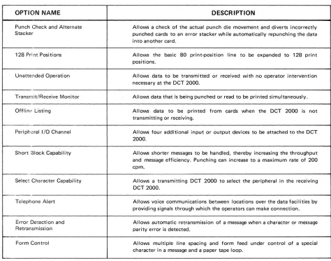
UNIVAC OCT2000
Field-Installable Options94 94 95
96
96
96 96 9797
99100
104105
45
. 10
I. INTRODUCTION
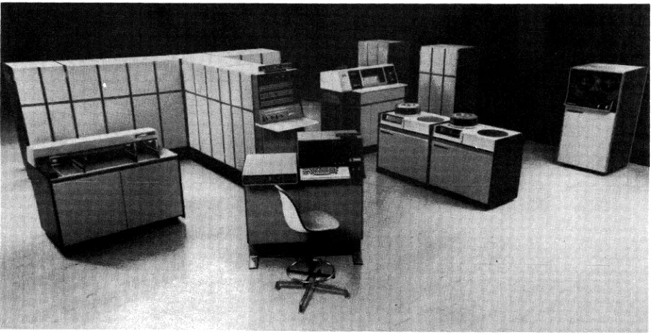
The UNIVAC 90/60 System, shown in Figure 1-1, is the latest and most powerful member of the UNIVAC Series 90 computer family. It is a general purpose, disc-oriented computer designed to function in many different data processing environments with equal operating efficiency.
The UN IVAC 90/60 System includes dynamic program relocatability. Two operating systems are available, OS/4, an enhanced version of the UNIVAC 9400 DOS, and OS/7, specifically designed to fully utilize the modern hardware of the UNIVAC 90/60 System. Up to 14 user programs may be concurrently executed while each is guaranteed its integrity by hardware storage protection. Another significant feature is the ease of transition from an IBM* 360/DOS to a UN IV AC 90/60 System.
The modular design of the UN IVAC 90/60 System, coupled with its high-speed main storage and I/O architecture provides a dependable base for future extensions. Changes in business demands, applications, programming techniques, system confiugration, or new terminal devices can be readily incoprorated into existing UN IVAC 90/60 Systems. This architecture extends the usefulness of the initial planning, programming, and operational procedures of a system.
Figure 1-1. UNIVAC 90/60 System
2. SYSTEM DESCRIPTION
2.1.
HIGHLIGHTS
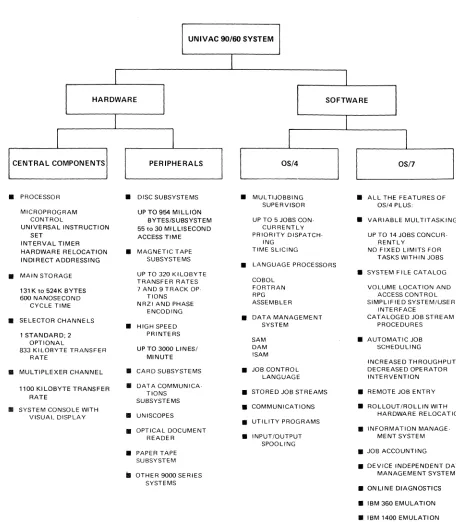
The UNIVAC 90/60 System consists fo central hardware components and a wide range of peripheral subsystems; including extensive data communications capabilities. Also, software support is provided by two operating systems: • OS/4
A versatile multi-jobbing operating system patterned after the UNIVAC 9400 disc operating system. This system is designed for smaller configurations and for those users not requiring the extended capabilities provided by OS/7.
• OS/7
A more sophisticated multi-tasking system with extended capabilities to meet the needs of larger configurations and more complex processing environments.
The highlights of the UNIVAC 90/60 System are shown in Figure
2-1.
A detailed description of the hardware and software components in the UNIVAC 90/60 System is given in the following sections of this document.UNIVAC 90/60 SYSTEM
I
I
I
HARDWARE SOFTWARE
I
I
I
I
1
I
CENTRAL COMPONENTS PERIPHERALS OS/4 OS/7
•
PROCESSOR•
DISC SUBSYSTEMS•
MUL TIJOBBING•
ALL THE FEATURES OFSUPERVISOR OS/4 PLUS:
MICROPROGRAM UP TO 954 MILLION
CONTROL BYTES/SUBSYSTEM UP TO 5 JOBS CON·
•
VARIABLE MULTITASKINGUNIVERSAL INSTRUCTION 55 to 30 MILLISECOND CURRENTLY
SET ACCESS TIME PRIORITY DISPATCH· UP TO 14 JOBS CONCUR·
INTERVAL TIMER ING RENTLY
HARDWARE RELOCATION
•
MAGNETIC TAPE TIME SLICING NO FIXED LIMITS FORINDIRECT ADDRESSING SUBSYSTEMS TASKS WITHIN JOBS
•
LANGUAGE PROCESSORS•
MAIN STORAGE UP TO 320 KILOBYTE•
SYSTEM FILE CATALOGTRANSFER RATES COBOL
131 K to 524K BYTES 7 AND 9 TRACK OP· FORTRAN VOLUME LOCATION AND
600 NANOSECOND TIONS RPG ACCESS CONTROL
CYCLE TIME NRZI AND PHASE ASSEMBLER SIMPLIFIED SYSTEM/USER
ENCODING INTERFACE
•
SELECTOR CHANNELS•
DATA MANAGEMENT CATALOGED JOB STREAM•
HIGH SPEED SYSTEM PROCEDURES1 STANDARD; 2 PRINTERS
OPTIONAL SAM
•
AUTOMATIC JOB833 KI LOBYTE TRANSFER UP TO 3000 LINES/ DAM SCHEDULING
RATE MINUTE ISAM
INCREASED THROUGHPUT
•
MULTIPLEXER CHANNEL•
CARD SUBSYSTEMS•
JOB CONTROL DECREASED OPERATORLANGUAGE INTERVENTION
1100 KI LOBYTE TRANSFER
•
DATA COMMUNICA·TlONS
•
STORED JOB STREAMS•
REMOTE JOB ENTRYRATE
SUBSYSTEMS
•
SYSTEM CONSOLE WITH•
COMMUNICATIONS•
ROLLOUT/ROLLIN WITHVISUAL DISPLAY
•
UNISCOPES HARDWARE RELOCATION•
UTILITY PROGRAMS•
OPTICAL DOCUMENT•
INFORMATION MANAGE·READER
•
INPUT/OUTPUT MENT SYSTEMSPOOLING
•
PAPER TAPE • JOB ACCOUNTINGSUBSYSTEM
• DEVICE INDEPENDENT DATA
iI OTHER 9000 SERIES MANAGEMENT SYSTEM
SYSTEMS
• ONLINE DIAGNOSTICS
• IBM 360 EMULATION
• IBM 1400 EMULATION
• SERIES 70 EMULATION
Figure 2-1. Highlights of UNIVAC 90/60 System Hardware and Software
2.2.
SYSTEM HARDWARE COMPONENTS
MAIN STORAGE EXPANSION
r---JI\~---~
,..---,1---;
--1r--rUj ,---
Ir--- - -, ,---- -- ---\
I : I I ' I I \ I , I I
I , I I , I I ' I I ,
I 32K ,32K I 32K: 32K I I 65K I 65K ' I 131 K I IBYTES:BYTES!IBYTES,BYTESI I BYTES I I BYTES ' I BYTES I
I :
I I : 'II : : :1 I II I II I I , I I
";:-_ _ _ _ _ _ _ :-;:-:-' L.. __ "! ___ ...J L.. __
t ___
J !- ______ .1 !.... _______ ' L _______________ .J131 164 196 229 262 327 393 540
UNIVAC 90/60 PROCESSOR
• FLOATING POINT • GENERAL REGISTERS • STORAGE PROTECTION • RECOVERY TIMER • INTERVAL TIMER • RELOCATION REGISTERS MULTIPLEXER CHANNEL
1---I
SUBCHANNEL EXPANSION
UNIVAC 8411, 8414, 8424, AND/OR 8440
01 R ECT ACC ESS SUBSYSTEM
1---,
I ~ UNISERVO 12/16 AND/, - OR 20 MAGNETIC I I TAPE SUBSYSTEM ,
1- _ _ _ _ _ _ _ _ ~
, - - - I
I STANDARD I I INTERFACE ~
I ADAPTER (SIA) :
,-
-
- -
- - - -
-
-600 CPM CARD READER
SUBSYSTEM
1000 CPM
r-
CARD READERG) SUBSYSTEM
-
G) 1100, 1600,2000 3000 LPM OR PRINTER SUBSYSTEM~
UNIVAC 90/60 SYSTEMI
CONSOLEI I
: UNIVAC 9000 SERI ES :
: (1) CHANNEL ADAPTER :
L _ _ _ _ _ _ _ _ _ _ .1
1"---,
,---,
R~~TE ~ DAT\~~~~~~~~ATIONS "
-+--i'
OPTIC~~AD~EC~MENT ; DEVICE,S) I _ _ _ _ _ _ _ _ _ _ _ DCS-I, IC, 4 OR 1 6 : : . 1 _ _ _ _ _ _ _ _ _ _ _ w' I,-
-
-
-
-
-
- -
- -
-,
,-
- - -
-
-
-
- -
-
--,
I UNISERVO V I - C ' I PAPER TAPE : I MAGNETIC TAPE ;..' -+~, SUBSYSTEM I
L ___
S~B':Y':T.:r: ___ : '- _ _ _ _ _ _ _ _ _ _ _ : ,- - - -, 1- - - -, I UNIVAC 9200, 9300, I I I I 9400,90/60, OR 90/70 '----1_-1 250 CPM CARD PUNCH I~
_ _':Y~~E~
____!
L ___
~~S~S~~
_ _ _1
,---1
,---1
1 MULTICHANNEL .. I _ ... --,' DISPLAY TERMINAL I : SWITCHES I MULTIPLEXER:
1- - - -I
r- - - -
~LEGEND: BASIC EQUIPMENT OPTIONAL EXPANSION
I UNISCOPE 100 ,
: DISPLAY TERMINAL
i
, __________ ...1
,---I
: EMULATION
,
'
_____
-,
,
, DIRECT I CONTROL I
TO ANOTHER UNIVAC 90/60 OR 90/70
SYSTEM
1"---1
___ : CONSOLE :, PRINTER I
'- - - -!
NOTES:
CD
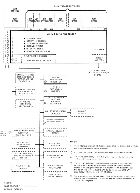
The multiplexer channel Interface has eight phYSical connections to which penpheral subsystems can be attached.CD
Each selector channel can accommodate eight high .. speed subsystems.G) A UN IVAC 9200, 9300, or 9400 Subsystem may prOVide the necessary reading and printing capability.
o
The UNIVAC 9000 Serres channel adapter mounted In the console may be connected to either the multiplexer channel or selector channel depending on throughput requirements. It provides for the control and transfer of data between the UNIVAC 90/60 System and a UNIVAC9200, 9300, 9400, 90/60, or a 90/70 System.
®
Any of these systems (if they have a 9000 Sefles or Sefles 90 Channel adapter) may be connected to the multiplexer or selector channel of a UNIVAC 90/60 System,Figure 2-2. UNIVAC 90/60 System Hardware
SYSTEM ORIENTATION
PROCESSOR
DATA ORGANIZATION
MAIN STORAGE CAPACITY
MAIN STORAGE PERFORMANCE
FLOATING-POINT ARITHMETIC
DIRECT CONTROL FEATURE
MULTIPLEXER CHANNEL
SELECTOR CHANNEL
REGISTERS
DISC STORAGE:
UNIVAC 8440 DISC SUBSYSTEM
UNIVAC 8424 DISC SUBSYSTEM
UNIVAC 8414 DISC SUBSYSTEM
UNIVAC 8411 DISC SUBSYSTEM
DISC
Microprogram control Versatile instruction set Hardware relocation Indirect addressing
Eight-bit bytes; four bytes per main storage access
131 K, 164K, 196K, 228K, 262K, 327K, 393K, or 524K bytes
A cycle time of 600 nanoseconds for a 4-byte access
Standard
Specialized interprocessor access feature for multiple UNIVAC 90/60 or 90/70 systems
Up to 8 subsystems - standard
Up to 15 subchannel addresses - standard
Up to 16 additional subchannel addresses - optional feature 175K bytes/second throughput rate
1 - standard
2 additional - optional feautre Up to 8 subsystems per channel
1100K bytes/second throughput rate per channel
16 for user program functions 16 for supervisor functions 8 for system working 1 for relocation
4 for floating-point arithmetic
119.28 million bytes/pack, maximum 954.24 million bytes/subsystem, maximum 624 K bytes/second transfer rate
30 milliseconds average access time
58.352 million bytes/pack, maximum 466.816 million bytes/subsystem, maximum 312K bytes/second transfer rate
30 milliseconds average access time
29.17 million bytes/pack, maximum 233.36 million bytes/subsystem, maximum
312K bytes/second transfer rate 60 milliseconds average access time
7.25 million bytes/pack, maximum 58 million bytes/subsystem, maximum
156K bytes/second transfer rate
MAGNETIC TAPE:
UNISERVO 20 SUBSYSTEM
UNISERVO 16 SUBSYSTEM UN ISERVO 12 SUBSYSTEM
UNISERVO VI-C SUBSYSTEM
CARD READER
PRINTER
CARD PUNCH
PAPER TAPE
OPTICAL DOCUMENT READER
COMMUN ICA TI ONS
2.2.1. Processor
7- and 9-track, phase and NRZI
320K bytes/second transfer rate
192 K bytes/second ttansfer rate
68K bytes/second transfer rate 34K bytes/second transfer rate
615 or 1000 cards/minute
325 to 3000 lines/minutes; 128 to 24 characters
250 cards/minute
300 characters/second - read 110 characters/second - punch
300 or 600 documents/minute
Up to 30 lines using a DCS-16 on the multiplexer channel
The UN IVAC 90/60 Processor performs control. arithmentic, and input/output operations. The control operations include determination of the sequence in which instructions are executed and interpretation and control of the execution of each instruction. Arithmetic hardware performs all data manipulation including logical operations, aritmmetic operations, data comparisons, and shifting. The input/output hardware initiates, directs, and monitors the transfer of data between main storage and the I/O subsystems.
The processor operates under microprogram control and contains an interval timer, recovery timer, storage protection, register stack, and I/O channels. It has provisions for floating-point arithmetic, and direct control for processor-to-processor communication.
The processor register stack contains 16 registers for supervisor functions, 16 registers for user program functions, and 4 registers for floatingcpoint arithmetic operations.
The UNIVAC 90/60 Processor uses industry-standard instructions. The instruction repertoire is an expansion of the repertoire of the UN IVAC 9400 System. The UNIVAC 90/60 System instruction repertoire also includes all of the nonprivileged instructions of the IBM System/360 Model 50.
2.2.2 I/O Channels
The UNIVAC 90/60 System is built with powerful high-speed I/O capabilities. From one to three selector channels are used for high-speed susbystems such as tape and disc. The mUltiplexer channel can service up to 16 low-speed subsystems such as printers and card readers.
2.2.2.1. Standard Interface Adapter (SIA)
The Standard Interface Adapter allows the connection of a Series 70 Communications Controller Multichannel (CCM) to a UNIVAC 90/60 Multiplexor Channel. Features are available that allow up to six CCMs to be attached to an SIA.
2.2.3. Communications
The UN IVAC 90/60 System offers added flexibility in communications-oriented applications. A wide variety of remote devices is available for use with this system. Connection to the processor is accomplished through the multi plexer channel.
The UNIVAC 90/60 System may be used with DATA-PHONe service, TWX networks, TELEX**, and Wideband or any combination of these services up to the maximum throughput of the system.
Communications capability is provided by means of a Data Communications Subsystem (DCS) connected to the mUltiplexer channel.
2.2.3.1. Data Communications Subsystem (DCS)
Smaller communications requirements are satisfied by the DCS. Each DCS uses one of the physical connections of the multiplexer channel. A DCS-1 or DCS-1C provides capability for communicating with one duplex line; a DCS-4 or DCS-16 provides capability for communicating with up to 4, or 14 duplex lines respectively.
2~.
SOFTWARE FEATURES
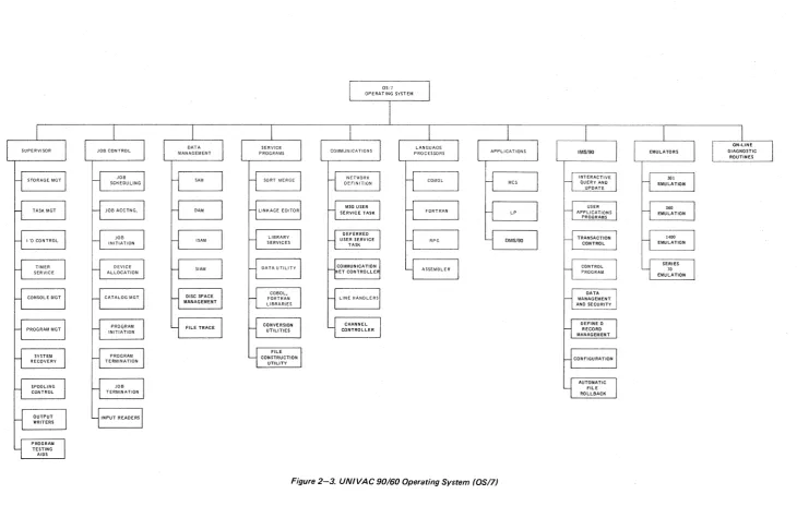
The operating system for the UNIVAC 90/60 System consists of a comprehensive set of control programs, utility service, and programming aids. (See Figure 2-3.) It is modular in design to fulfill a wide range of data processing requirements. The user can select the precise level of software capability to match his configuration. Control programs provide for communications processing and random and sequential batch processing. Data to be processed can be introduced to the system from either central or remote locations.
2.3.1. Supervisor
The supervisor is the part of the operating system that operates with user programs to provide the control necessary for optimum utilization ofthe UNIVAC 90/60 System hardware and software.
2.3.1.1.
Multijobbing/MultitaskingThe UN IV AC 90/60 System can concurrently process from 1 to 14 jobs. Each job consists of one or more job steps (programs) which are executed serially. Additionally, a job step may have one or more tasks which are executed concurrently. This structure allows the user complete flexibility in determining the use of the system and in scheduling the tasks to be done.
The allocation of processor time is based on a system switch list which contains information about switching priorities, time-slice values, and processor utilization.
The number of priorities and the initial time-slice values for each priority level are provided by the user at system generation. Priority for a given job may be changed by the system or the operator within predetermined limits.
2.3.1.2.
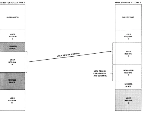
Rollout/RollinAll main storage addresses generated by problem programs are hardware restricted to being job-region-relative addresses. Hardware relocation registers which are managed by the operating system are used to locate job regions in main storage. This facility provides for effective rollout/rollin of jobs without regard to prior addressing constraints. For example, a high priority job may request additional main storage space to satisfy a critical dynamic requirement. In order to provide contiguous storage, it may be necessary to roll out a lower priority job to mass storage. This reduces main storage fragmentation, thus increasing main storage utilization. The lower priority job, when returned to main storage, can be loaded into a different absolute area of main storage.
2.3.2.
Data ManagementData management is that part of the software that provides a convenient and easy-to-use interface between user programs and the hardware-oriented I/O portions of the supervisor. The data management facilities provide benefits such as file organization, record blocking and deblocking, buffering, data validation, label processing, and device independence.
Data management offers four methods of accessing files. These methods are:
• Sequential Access Method (SAM)
• Direct Access Method (DAM)
• Indexed-Sequential Access Method (lSAM)
• System Integrated Access Method (SIAM)
The first three access methods are IBM/360 DOS compatible. The fourth access method is designed for system usage.
o
2.3.3. Job Control
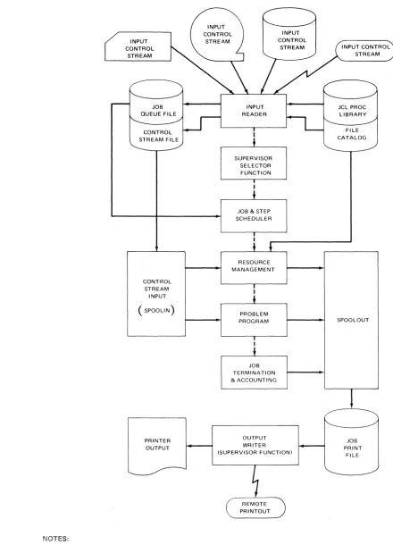
Job control is the nonresident component of the UNIVAC OS/7 Operating System (OS17) that manages the system resources (main storage, software facilities, and peripheral devices), prepares jobs for processing, and initiates program execution. A job is a user-submitted task or unit of work to be performed. Each job can be divided into job steps to be executed serially. Job steps are made up of problem programs, with each job step containing only one request for program execution.
The services performed by OS17 job control are directed by the user through control statements known as the job control language. These control statements convey information required by the operating system to initiate and control the processing of jobs, such as identifying the job and the programs that comprise it and specifying main storage requirements and peripheral device assignments necessary for job execution.
Figure 2-4 shows job flow and the facilities provided by job control.
2.3.3.1. System File Catalog
Use of the system file catalog results in the ability to locate files automatically when only the file identifier is specified. Successive generations of data files may be cataloged and subsequently located by a relative generation number.
Also, control statement sequences can be prepared once and stored in a cataloged library; then the sequences can be called upon as frequently as desired. These control statement sequences are sometimes referred to as cataloged procedures.
2.3.3.2. Automatic Scheduling
The UN IVAC 90/60 System files all jobs submitted to the system into an input work queue based on a user-specified scheduling priority. The jobs may then be initiated automatically according to the scheduling priorities and the availability of system resources. The system operator is permitted to override the automatic job selection process of the system.
2.3.4. Other Features
The UN I V AC 90/60 System software also has the following salient features:
• Auomatic buffering (spooling) to disc or magnetic tape for such peripherals as the card reader or printer.
• Effective methods for recovery from device errors and system failures.
• Extensive job accounting information suitable to both local and remote batch environments.
• Use of reentrant routines to increase the utilization of main storage and decrease I/O traffic caused by program retrievals.
• Job scheduling and general operations support for a fixed-partitioned system can be optionally selected by the user.
• Emulation for the following Data Processing Systems in a multijobbing environment: IBM 301, 360, 1401, 1440, 1460, and Series 70.
NOTES:
INPUT CONTROL
STREAM
CONTROL STREAM
INPUT ( SPOOLlN)
PRINTER OUTPUT
INPUT READER
I
+
SUPERVISOR SELECTOR FUNCTION
JOB & STEP SCHEDULER
RESOURCE MANAGEMENT
PROBLEM PROGRAM
JOB TERMINATION & ACCOUNTING
OUTPUT WRITER (SUPERVISOR FUNCTION)
1. Solid arrows indicate data; broken arrows indicate control.
INPUT CONTROL STREAM
JCL PROC LIBRARY FILE CATALOG
SPOOLOUT
JOB PRINT
FILE
3. CENTRAL HARDWARE
3.1. GENERAL
The central hardware for the UN IVAC 90/60 System consists of the following components:
• Processor
• System Console
• Main Storage
Each of these components is discussed in the following paragraphs.
3.2.
PROCESSORThe UNIVAC 90/60 Processor is a medium-scale, high-performance processor with random or sequential batch processing, scientific processing, and communications processing capabilities. The processor operates under microprogram control. The micro code is resident in a separate semiconductor control storage which has a writable section.
The UN IV AC 90/60 Processor has the following standard characteristics:
•
I ndustry-compatible instruction repertoire•
Hardware program relocation algorithm•
Indirect addressing•
Write or read/write storage protection•
Multiple control modes•
One multiplexer I/O channel•
One selector I/O channel•
A 15-level interrupt structure•
Program status word interrupt control•
Recovery timer facility• Interval timer facility
• Parity generation and checking on the channel and storage buses • System console
• Floating-point arithmetic control
The processor also has provisions for the following optional features: • Up to two additional selector I/O channels
• Subchannel expansion and expanded interface features to enhance the mUltiplexer I/O channel capability • Direct control and external interrupt
Arithmetic and input/output control comprise the major functions of the processor. The hardware associated with these functions is described in the following paragraphs.
3.2.1. Arithmetic Hardware
The arithmetic hardware performs all logical operations, arithmetic operations, data comparisons, and shifting. Fixed-point binary arithmetic uses the twos complement number representation. Floating-point and decimal arithmetic use signed absolute value number representation. This hardware also performs single or double indexing of operand addresses together with address relocation and indirect addressing.
3.2.1.1. Register Stack
The register stack contains general purpose registers in two sets of 16 each, four optional registers for floating-point arithmetic operations, eight working registers, and one relocation register.
• General Purpose Registers
The processor can reference two sets of 16 general purpose registers. One set is reserved for the supervisor while the other set can be used by user programs. This design reduces the interrupt processing time overhead required when only a single set of general registers is used. When the processing mode is changed between user program and supervisor modes, the following steps which would be required in single register systems are unnecessary:
1. Store the contents of user program registers. 2. Load the executive routine data into the registers. 3. Store the executive routine data.
4. Reload the user program data back into the registers.
• Floating-Point Registers
Four doubleword floating-point registers are provided to avoid unnecessary storing and loading operations for results and operand. These registers are numbered 0, 2, 4, and 6. For long format instructions, both words of the register are involved in the operation. For short format instructions, only the first word in the register is involved in the operation; the content of the second word in the register is ignored and not changed. If an odd-numbered register is specified, a program exception interrupt request in generated.
• Working Registers
These registers are used for temporaty storage of operands and intermediate results when executing decimal arithemetic operations. Their primary function is to increase execution speed. These registers are not addressable by the user.
• Relocation Register
This register is used by both the processor and the input/output channels to provide automatic program relocation.
3.2.1.2.
Fixed-Point ArithmeticFixed-point numbers have a fixed-length format comprising a sign bit followed by an integer field. When the sign bit is 1, the integer represents a negative value; when the sign bit is 0, the integer represents a positive value.
r
SIGNHalfword Format
101,
INTEGERlsi
Fullword Format
If
SIGN
INTEGER
Doubleword Format
II
SIGN
INTEGER
\0
~ _ _ _ \ 63
When held in one of the 16 general registers, a fixed-point number is generally treated as a 32-bit operand. When a halfword fixed-point number is called from storage and loaded into a register, the sign is extended to the left to fill the fullword register. The contents of the register are then handled as a fullword operand in fixed-point arithmetic operations.
Certain operations use a 64-bit operand comprised of one sign bit followed by a 63-bit integer field. The 64-bit operand is located in two adjacent general registers, and it is addressed by an even address referring to the lower-numbered register of the pair.
When fixed-point data is located in storage, it may be stored as a halfword, fullword, or doubleword. This data must be located on the integral storage boundary of its associated format.
3.2.1.3. Floating-Point Arithmetic
The UNIVAC 90/60 System can provide floating-point arithmetic operations as an optional feature. A floating-point number comprises a biased exponent (characteristic) and a signed fraction (mantissa). The biased exponent is expressed in excess 64 binary notation; the fraction is expressed as a hexadecimal number having a radix point to the left of the high-order digit. The quantity expressed by the full floating-point number is the product of the fraction and the number 16 raised to the power of the biased exponent minus 64.
Floating-point numbers are either a fullword (short format), or a doubleword (long format) in length. Both formats can be used in main storage or in the floating-point registers. In either format, bit 0 is the sign bit of the fraction, and bits 1 through 7 are exponent. The fraction field comprises bits 8 through 31 in the short format and bits 8 through 63 in the long format.
r
SIGNShort Format EXPONENT FRACTION
0 1 7 8 31
Long Format
SIGN
4-L.--1~PON--,--ENT)18
_ F _ R A C T I O N~{
0
The floating-point instruction set provides for loading, adding, subtracting, comparing, multiplying, dividing, storing, and sign control of short or long format operands. Short format operands provide faster processing and require less storage space than long format operands. Long format operands provide greater precision in computation.
A normalized floating-point number has a nonzero high-order hexadecimal fraction digit and is the most significant representation of a given quantity. The process of normalization consists of shifting the fraction to the left until the high-order hexadecimal digit is nonzero, and reducing the characteristic by the number of shifts. A fraction with one or more high-order digits of zero is unnormalized. A zero fraction cannot be normalized.
3.2.1.4. Decimal Arithmetic
In the unpacked decimal format, each byte contains one digit of a multi digit number. The byte is divided into two equal fields, a zone field and a digit field. A zone value is represented in the most significant four bits, and the digit is represented in the lease significant four bits. The zone portion of the lease significant byte specifies the sign of the number. The unpacked format must be used when data is to be processed by certain I/O devices such as the printer. The format of a 3-digit operand follows:
0
BYTE
~
ZONE DIGIT ZONE
7 8
DIGIT SIGN
15 16
DIGIT
23
UNPACKED DECIMAL OPERAND
In the packed format, each byte contains two digits. The least significant four bits of the least significant byte provide the sign of the number. The packed decimal format is used for all decimal arithmetic operations. The format of a 4-digit number follows:
0
BYTE
~
ZERO
FILL DIGIT DIGIT
7 8
DIGIT DIGIT
15 16
SIGN
23
PACKED DECIMAL OPERAND
Decimal numbers (0 through9) are represented in the 4-bit binary coded decimal form (0000 through 1001). The codes 1010 through 1111 are used for sign codes. The binary values 1011 and 1101 represent a minus sign and the binary values 1010,1100,1110, and 1111 represent a plus sign. This assignment of sign codes permits the use of either of two conventions: American National Standard Code for Information Interchange (ASCII) modified to eight bits, or Extended Binary Coded Decimal Interchange Code (EBCDIC). The codes 1100 (plus) and 1101 (minus) are hardware-generated in either the ASCII or EBCDIC mode. A control bit in the program status word determines whether the system is to operate in the ASCII or the EBCDIC mode. See Appendix C.
3.2.1.5. Logical Operations
Logical operations such as comparing, translating, editing, bit setting, and bit testing are performed by the arithmetic section. Logical operations can be performed in the general purpose registers or main storage. The instruction used determines whether the logical operation is to be performed in main storage or in a register.
3.2.2. Input/Output
The input/output (I/O) hardware of the UNIVAC 90/60 Processor initiates, directs, and monitors the transfer of data between storage and the peripheral subsystems. After the I/O instruction has been initiated, the data transfer is performed concurrently with other processor functions. The selector channels, the multiplexer channel, and the processor can all operate concurrently.
The I/O hardware consists of I/O control logic and the input/output channels using a standard UN IVAC Series 90 I/O interface to connect channels with the unit controllers. This interface is identical for all the I/O control units designed for use with all I/O devices currently available on UNIVAC Series 90 Systems as well as for future devices.
3.2.2.1. Selector Channels
One selector channel in included in the basic system configuration; two selector channels are available as optional features to the basic configuration. High-speed devices, such as UNISERVO 12, 16, or 20 Magnetic Tape Sybsystems, and UNIVAC 8411, 8414, 8424 and/or 8440 Disc Subsystems, are connected only to the selector channels.
Eight standard control units may be attached to each selector channel. Up to 16 I/O devices can be attached to each of the eight control units depending on the particular subsystem selected. The devices attached to a selector channel are serviced on a one-at-a-time basis. That is, once transfer of data is initiated between a particular device and main storage, that tranafer must be completed before another device on the channel can transfer data.
3.2.2.2. Multiplexer Channel
The processor has one multiplexer channel which has eight physical connections to which standard control units (for such devices as a card reader, card punch, or line printer, and a Data Communications Subsystem (DCS) can be attached. The address format for the multiplexer channel provides for 15 subchannel addresses. These can be a combination of standard and, if a DCS is conncted to the multiplexer channel, DCS subchannel addresses.
Subchannel expansion can be added to the basic multiplexer channel which provides an additional 16 subchannel addresses for a total of 31.
The standard control unit occupies one physical connection and uses one standard subchannel address. Devices such as the system console, card reader, line printer, or UNISERVO VI-C Magnetic Tape Subsystem are connected to the processor through the standard control unit. Each DCS occupies one physical connection but uses up to 28 DCS subchannel addresses. The DCS may be used for data communications over 1 to 14 communication lines.
3.2.3. Processor Modes
There are seven bits in the active program status word which determine processor modes of operation. These modes of operation are described in the following paragraphs.
• Selection of Problem or Supervisor Mode
When operating in the problem mode, a program cannot execute privileged instructions. Also, the program performs only the main storage operations permitted by the storage protection key. When operating in the supervisor mode, there are no restrictions on the instruction usage, and storage protection still applies.
• Selection of Register Set
The processor contains two sets of general purpose registers. The user program general registers can be used during the execution of instructions in the problem register mode. Similarly, the supervisor general registers can be used by the supervisor.
• Selection of ASCII or EBCDIC Code Interpretation
• Processor Wait Mode
The processor wait mode is provided to allow the program to suspend instruction processing. This mode is particularly useful when exceptionally high I/O activity precludes a meaningful rate of job execution, when all jobs are waiting for I/O operations to be completed, and when no jobs are in the system.
• Program Trace Mode
When operating in this mode, the execution of a successful branch instruction causes the address of the instruction following the branch instruction and the instruction length code of the branch instruction to be written into a table in main storage.
• Monitor Mode
A program analysis level interrupt is generated prior to the execution of all instructions fetched while in this mode.
• 9400 Compatibility Mode
This mode is provided to inform the software of UNIVAC 9400 System compatibility requirements.
• Special Emulation Mode
This mode permits the UNIVAC 90/60 Processor to access microprograms stored in the writable section of control storage.
3.2.4. Interval Timer
An interval timer is included as an integral component of the UNIVAC 90/60 Processor. It prQvides the software with a relative running-time count and an incremental interrupt count. The running time counter and the interrupt counter are updated once every millisecond.
The running time counter allows for a continuous measure of elapsed time. The count may be incremented or decremented. The counter value changes from maximum to zero after incrementing, and from zero to maximum after decrementing without causing program intervention.
The interrupt counter allows the interval between interrupts to range from one millisecond to 64 seconds.
3.2.5. Interrupt Processing Control
The UNIVAC 90/60 System contains an efficient multilevel interrupt system. The processor can react to external and internal error conditions or monitoring conditions by means of this interrupt system. The hardware and associated software allow the processor to change from the user program state to the privileged or supervisor state. The types of interrupts employed in the UNIVAC 90/60 System are:
• Machine Checks
This interrupt request occurs when a hardware malfunction is detected by the processor or when a hardware malfunction not identified as a subsystem fault is detected by the I/O section, or when a program exception is generated while being masked.
• Program Exception
This interrupt request occurs when a program error is detected by the hardware. The interrupt is generated as a result of one of the following:
Operation Exception
An illegal processor operation has been attempted or an operation using a nonexistent processor feature has been attempted.
Privileged Operation Exception
A privileged operation has been encountered in a problem mode. Execute Exception
The object of an execute instruction is another execute instruction. Protection Exception
The key in key storage does not match the key in the program status word. Addressing Exception
Reference is made to a nonexistent storage location. Specification Exception
An integral boundary reference error has been made; general register pairs or floating-point registers have been specified incorrectly; the length of decimal fields is incorrect. The control indicators set by an LBR or BeRE instruction are invalid.
Data Exception
The operands in decimal and editing operations contain incorrect digit and sign codes; decimal arithmetic fields are aligned incorrectly.
Fixed-Point Overflow Exception
The result of a fixed-point arithmetic operation has caused a high-order carry, or a shift operation has
caused the loss of significant bits. '
Fixed-Point Divide Exception
The quotient exceeds the size of the associated register, or the result of a decimal-to-binary conversion operation exceeds 31 bits.
Decimal Overflow Exception
The capacity of the result field is exceeded during a decimal arithmetic operation. Decimal Divide Exception
Exponent Overflow Exception
The characteristic result exceeds 127 during a floating-point arithmetic operation. Exponent Underflow Exception
The characteristic result is less than zero during a floating-point operation.
Significance Exception
A floating-point addition or subtraction results in a zero fraction. Floating-Point Divide Exception
Floating-point division is attempted with a zero divisor fraction. Indirect Address Exception
An indirect address control word (lACW) with an incorrect format has been referenced. Indirect Address Specification Exception
A main storage reference has exceeded the 8-level indirect addressing capability. • Program Analysis
this interrupt request occurs during program monitoring and certain program tracing operations. • Supervisor Call
This interrupt request occurs as a result of the execution of a supervisor call (SVC) instruction and may have up to 256 different states which are established by the software.
• External
This interrupt is associated with maintenance trace, interrupt key, and the direct control and external interrupt feature. The direct control and external interrupt feature provides for the direct connection between two UNIVAC 90/6Q Processors. The external interrupt request associated with this feature occurs when certain of the signal-in lines associated with the direct control interface of an object processor are enabled. The states within this level are:
Maintenance Trace Interrupt Key
External Signal 2 State * External Signal 3 State * External Signal 4 State * External Signal 5 State * External Signal 6 State* External Signal 7 State *
*This state is a part of the direct control and external interrupt feature.
• Timer
This interrupt request occurs when a present time interval expires. • Other Input/Output Channels
An interrupt request occurs when status is generated or received from a subsystem during channel or subchannel op~rations. Each channel has its own interrupt to reduce software overhead associated with interrupt analysis.
Selector Channel 1 Selector Channel 2 Selector Channel 3
MUltiplexer Channel Standard Multiplexer Channel DCS
3.2.6.
Instruction RepertoireThe power and flexibility of the UNIVAC 90/60 System are reflected in the instruction repertoire and their execution times. The full repertoire includes all nonprivileged instructions of the IBM System/360 universal instruction set. The instruction repertoire has also been enhanced to facilitate dynamic program relocation and indirect addressing.
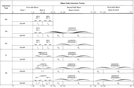
3.2.6.1.
Instruction TypesInstruction Type RR RX RS SI SS
Byte 1
opcode
opcode
opcode
opcode
First Half Word Byte 2
11112
I I
I REG REG I
I OP 1 OP"2 I
i-;~I~~~i
I
I REG :
I OP 1 I I
~-I
r,I
x2I
I '
I REG REG
i
I OP 1 OP 3 Ii
-',-I
-'3-
i
I :
I IMMEDIATE I I OPERAN D I I ____________ ,
I
I
Object Code Instruction Format
19 120
Second Half Word Bytes 3 and 4
31 32
ADDRESS OPERAND 2
./'-...
--ADDRESS OPE RAN D 1
~
35 136
Third Half Word Bytes 5 and 6
47
I
>-_ _ _ oP_co_d_e _ _ + _ _ _ I-_, _ _---1If---'b,'--,L ____
----'d,'--_ _ _-+I_b-=2_..J.I ____
---'d2
=--_ _ _ --II I I
I LENGTH I ADDRESS I
: OP I OP 2 : OPERAND I I _.~ ____ _ _ . . I - - ~ _ _ _ I
ADDRESS OPERAND 2
~I opcode
I
1,-'
I
12 - 'I
I
10 7 Is 11 112 15 116 19 120 31 I 32 35 136 47 I
Figure 3-1. Basic Instruction Formats (Object Code Form)
• Register to Register (R R) Instructions
The R R type instructions are used to process data contained in registers. The maximum length of the data that can be handled is a doubleword. The data may be a signed or unsigned binary number, a short or long format floating-point number, or a decimal number, depending on the specified operation. Operand 1 specifies either a register or a mask. Operand 2 specifies a register.
Some R R type instructions use both operands 1 and 2 as an immediate data operand.
• Register and Indexed Storage (RX) Instructions The RX type instructions are used to process data between registers and indexed storage. The maximum length of the operand that can be handled is a doubleword. The data may be a signed or unsigned binary number, a shour or long format floating-point number, or a decimal number. Operand 1 specifies a register or a mask. Operand 2 specifies a main storage location, which may be further modified by a relocation and indirect addressing, and the number of a register containing an index value.
• Register to Storage (RS) Instructions
The RS type instructions are used to perform multiple register and storage operations as well as data shifting. The first and third operands specify the numbers of two general registers or the boundaries for general register usage. Operand 2 specifies a main storage location, which may be further modified by relocation and indirect addressing, or maybe a shift count.
• Storage and Immediate Operand (SI) Instructions
The SI type instructions are used to perform operations on an 8-bit value, called immediate data, and an operand in storage. Operand 2 specifies the immediate data or mask. Operand 1 specifies a 1-byte or halfword storage location which may be further modified by relocation and indirect addressing depending on the operation.
• Storage to Storage (SS) Instructions
The SS type instructions are used to perform operations on two operands located in storage. In logical operations the operands are assumed to be equal in length and may be from 1 to 256 bytes. In decimal operations the operands may be different lengths and may be from 1 to 16 bytes.
SYMBOL
OPCODE
L
OP1
OP2
OP3
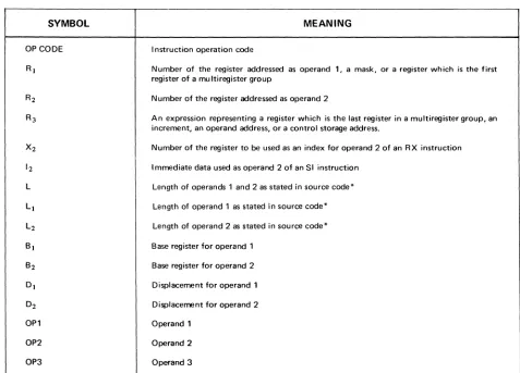
Table 3-1. Svmbols Used to Describe Operand Formats
MEANING
I nstruction operation code
Number of the register addressed as operand 1, a mask, or a register which is the first register of a mu Itiregister group
Number of the register addressed as operand 2
An expression representing a register which is the last register in a multiregister group, an increment, an operand address, or a control storage address.
Number of the register to be used as an index for operand 2 of an RX instruction
Immediate data used as operand 2 of an SI instruction
Length of operands 1 and 2 as stated in source code*
Length of operand 1 as stated in source code*
Length of operand 2 as stated in source code*
Base register for operand 1
Base register for operand 2
Displacement for operand 1
Displacement for operand 2
Operand 1
Operand 2
Operand 3
3.2.6.2.
Nonprivileged Instruction Set
This instruction set includes the 132 nonprivileged instructions of the IBM System/360 universal instruction set, an add immediate (AI) instruction, three instructions for indirect addressing (BALE, LBR, and BCRE), and an emulation aid (EA) instruction. Instructions are provided to process a fixed-length binary numbers, floating-point numbers, packed and unpacked decimal numbers, and EBCDIC or ASCII characters. Data may be transferred between main storage and the user program set of general registers and from stroage to storage. The operations of shifting, branching, and logical functions are also included. All nonprivileged instructions are listed in Appendix A.
3.2.6.3.
Privileged I nstruction Set
The privileged instruction set is used by the software operating system when operating in the supervisory state. In this state, all instructions are valid and can be executed. This set of instructions includes the facility to load the current program status word (PSW), entirely or in parts; to load and store the contents of the key storage; to utilize the direct control and external interrupt feature; to control the I/O channels and subsystems; and to load the writable section of control storage. Instructions in the privileged set cannot be executed in a user program. The privileged instructions are listed in Appendix A.
3.2.6.4.
Indirect Addressing
The UN IVAC 90/60 System non privileged instruction set is extended to include three additional instructions: load base relativize (LBR), branch and link external (BALE), and branch on condition to return external (BCRE). These instructions are the operating commands for the UNIVAC 90/60 indirect addressing function. The indirect addressing function is a unique design which has no equivalent in the current industry-compatible instruction set.
Indirect addressing provides uncomplicated entry to reentrant system subroutines under control of the supervisor. The user need not directly indicate the address of the subroutine in a supervisor request. Instead, the reference to the subroutine is implicity indicated in the transfer address of the BALE instruction. The BALE instruction then references the associated indirect address control word (I ACW) contained in a vector table in main storage. The IACW indicates the address of the reference; the IACW also has control bits which can .indicate additional indirection (up to eight levels), switch from relative or absolute addressing, or cause program exception interrupts. The BALE instruction also provides a means for the user to examine the current control indicators.
Instructions used for operations such as shifting and constant generation are not sensitive to the operand control indicators.
The tndirect addressing function in the UNIVAC 90/60 System has the following advantages when referencing system subroutines ..
• No interrupt occurs (as with SVC), reducing system overhead, when the subroutine is in main storage. • The supervisor is capable of moving subroutines without impacting user programs.
• User region sizes are reduced, since code with a low usage frequency is moved into main storage only when referenced.
• The user can place application subroutines or data bases, such as rate tables, under supervisor control.
3.2.6.5.
Address Relocation
Another unique design feature in the UN (VAC 90/60 System is address relocation. The address relocation scheme utilizes a hardware relocating register that is dynamically loaded by hardware from a fixed main storage position each time the protection key of the program in control of the system changes.
These relocation registers define virtual address zero in the associated regions of main storage, and the contents of a register are automatically added to all the storage references generated by a user porgram.
This scheme provides a flexible and efficient rollout/rollin capability, because the supervisor can locate the rolled-in program in any portion of main storage by adjusting the associated relocation register.
Address relocation increases system throughout because:
• Storage utilization is improved. There is a decrease in checkerboarding and a resulting reduction of unused space. This unused space can be consolidated to provide additional main storage regions of useful size.
• Except in special cases, the program loader does not have to relocate programs as they are being loaded. This saves considerable processor time.
3.3.
MAIN STORAGE
The main storage of the UNIVAC 90/60 System consists of high-speed, semi-conductor storage developed for the UNIVAC Series 90 computers: Main storage is contained in freestanding units with 600 nanosecond read or write cycle time for a fullword.
Minimum storage size is 131,072 bytes. This can be expanded by the following: 32,768-byte increments up to 262,144 bytes;
Address and data are checked for odd parity.
Each main storage cabinet is equipped with seven switches. These switches are used as the most significant bits of the cabinet starting address. If it becomes necessary to place a 131 K storage module offline, the switches on the cabined with the highest addresses can be set to the starting address of the module removed from service. This permits the remaining online modules to have sequential addresses.
3.3.1.
INFORMATION POSITIONING
Locations in main storage are addressed consecutively from 0 through a maximum of 1,048,575. Bytes may be accessed separately or in groups. A group of bytes is addressed by the leftmost byte of the group. The bits in a byte are numbered from left to right starting with zero.
Ib
H
bF Ib F
~
Ib
I
o
7
Halfword data formats consist of two consecutive bytes.
0 - - - - 7 8 - - - - 1 5
Fullword data formats consist of four consecutive bytes.
0 - - - - 7 8 - - - 1 5 1 6 - - - 2 3 2 4 - - - 3 1
Doubleword data formats consist of eight consecutive bytes.
Variable data formats consist of a variable number of consecutive bytes.
0 - - - - 7 0 - - - - 7
First Byte Last Byte
Fixed-length fields, such as halfwords and fullwords, have integral boundaries. Fixed-length fields must be loaded into main storage so that the address is evenly divisible by the field length (in bytes). Thus, a halfword must have an address that is a multiple of 2, a fullword must have an address that is a multiple of 4, and a doubleword must have an address that is a multiple of 8.
Variable-length data fields are not restricted by boundaries. Instructions must begin on halfword boundaries and must have lengths of two, four, or six bytes.
3.3.2. Low Order Storage
The low order 640 bytes of main storage have been reserved to contain specific operating information. The information stored in these locations is accessed by the hardware and the operating system during the execution of appropriate functions. The operating system provides for the loading and protecting of the information in these locations.
3.3.3 Storage Protection
Program integrity in a multijobbing environment is guaranteed by the storage protection capability implemented in the processor and I/O channels. Sixteen keys are provided for this purpose. Write and read/write protection are provided.
Protection is provided in 2048-byte blocks of main storage. The supervisor assigns each block a storage protection key. A comparison is made between a requester key and the appropriate storage protection key. When the keys match, the storage operation specified is performed. When the keys do not match and the block specifies write storage protection, a read operation is allowed and a write operation is disallowed. When the keys do not match and the block specifies read/write storage protection, all operations are disallowed. In the case of disallowed operations, a program exception interrupt request is generated.
3.3.4. Program Relocation Registers
There are 16 program relocation registers located in low order main storage. These registers serve as base registers for the program modules in storage. A copy of the contents of the register associated with the current program status word is stored in a register in the control hardware to facilitate rapid storage addressing.
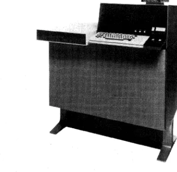
3.4. SYSTEM CONSOLE
The UN IV AC 90/60 System Console is a freestanding input/output device for directing and monitoring the operation of the system. (See Figure 3-2.) The system console provides a centralized location for initial load control, run/stop control, and system status monitoring. The system console consists of a keyboard and visual display unit, switches and indicators, which are housed in a cabinet that is separate from the processor. The system console communicates with the processor through the multiplexer channel.
The keyboard and visual display unit, a UNISCOPE 100 Display Terminal, is capable of displaying 96 characters, including uppercase and lowercase alphabets, on the visual display screen. The visual display screen has a screen capacity of 1024 characters at a time. The total number of characters displayed is subdivided into 16 rows of 24 characters each. All communications between the operator and the operating system are displayed. The operator controls consist of an alphanumeric typewriter keyboard, cursor control keys, editing keys, data control keys, control knobs, and indicators. Thus, the operator can key-in a message, see it displayed on the visual display screen, edit it, and transm it it to the processor.
The system console includes all controls and indicators necessary to operate and monitor the operation of the system. A panel is provided to allow operator control of the switches, and to present an indication of the system configuration for the operator.
The system console cabinet also provides space for mounting the UNIVAC 9000 Series Channel Adapter.
As an optional feature, a UNIVAC incremental printer can be connected to the system console to provide additional hard copy output. It may be used to duplicate all messages displayed on the visual display screen. The UN IVAC incremental printer is mounted in a separate cabinet. This printer has a 94-character set (including uppercase and lowercase), a 132-position print line, prints up to 30 characters per second, and has a paper feed rate of 30 I ines per second.
4. PERIPHERAL EQUIPMENT
4.1. GENERAL
A full line of onsite peripheral equipment is available for use with the UNIVAC 90/60 System. These subsystems are:
• UNIVAC 8411 Disc Subsystem
• UNIVAC 8414 Disc Subsystem
• UNIVAC 8424 Disc Subsystem
• UNIVAC 8440 Disc Subsystem
• UNISERVO VI-C Magnetic Tape Subsystem
• UNISERVO 12/16 Magnetic Tape Subsystem
• UNISERVO 20 Magnetic Tape Subsystem
• UNIVAC 0711 Card Reader Subsystem
• UN IV AC 0716 Card Reader Subsystem
• UNIVAC 0768 Printer Subsystem
• UNIVAC 0770 Printer Subsystem
• UNIVAC 0604 Card Punch Subsystem
• UNIVAC 0920 Paper Tape Subsystem
• UNIVAC 2703 Optical Document Reader
• UNISCOPE 100 Display Terminal
• UNIVAC 9000 Series Channel Adapter may be used to attach the following systems:
UN IV AC 9200 System
UNIVAC 9400 System
UNIVAC 90/60 System
UN I V AC 90170 System
4.2.
DISC SUBSYSTEMSUNIVAC 8411/8414 Disc Subsystem
CONTROL UNIT DISC STORAGE UNIT
UNIVAC 8424/8440 Disc Subsystem
CHARACTERISTIC UNIVAC UNIVAC UNIVAC UNIVAC 8411 8414 8424 8440
NUMBER OF DRIVES 1-8 2-8 2-8 2-8
NUMBER OF DISC DRIVES
PER CABINET 2 2
NUMBER OF R!W HEAD
ACCESSOR MECHANISMS PER DISC DRIVE
NUMBER OF R!W HEADS PER
DISC DRIVE 10 20 20 20
NUMBER OF TRACKS PER
DISC SURFACE 203 203 406 406
NUMBER OF DATA RECORDING
SURFACES PER DISC DRIVE 10 20 20 20
NUMBER OF USABLE TRACKS
PER SURFACE 200 200 400 400
NUMBER OF USABLE TRACKS
PER DISC DRIVE 2000 4000 8000 8120
MAXIMUM NUMBER OF BYTES
PER TRACK 3625 7294 7294 14,910
CAPACITY (8oBIT BYTES
PER DISC PAGK) 7,250,000 29,176,000 58,352,000 119,280,000
MINIMUM ARM POSITIONING
TIME 25ms 25 ms 10 ms 10ms
AVERAGE ARM POSITIONING
TIME 75ms 60 ms 30ms 30ms
MAXIMUM ARM POSITIONING
TIME 135ms 130ms 55 ms 55ms
AVERAGE LATENCY TIME 12.5 ms 12.5ms 12.5 ms 12.5 ms
MAXIMUM LATENCY TIME 25 ms 25 ms 25ms 25ms
AVERAGE ACCESS TIME 87.5 ms 72.5 ms 42.5 ms 42.5 ms
MAXIMUM ACCESS TIME 160 ms 155 ms 55 ms 80 ms
DISC DRIVE SPEED 2400 rpm 2400 rpm 2400 rpm 2400 rpm
STORAGE TRANSFER
RATE 156,000 bytes! 312,000 bytes! 312,000 bytes! 624,000 bytes!
The availability of four different disc subsystems enables the user to choose the disc storage facilities best suited to the installation. These facilities include the lower cost UNIVAC 8411 Disc Subsystem, the higher capacity UNIVAC 8414 Disc Subsystem, and the high performance large capacity of the UNIVAC 8424 and 8440 Disc Subsystems. A disc subsystem is attached to the processor by means of a selector channel. These subsystems offer many advantages in standard data processing as well as in communications operations, especially in a