F R O N T I E R L E T T E R
Open Access
On volume-source representations based
on the representation theorem
Mie Ichihara
1*†, Tetsuya Kusakabe
1†, Nobuki Kame
1and Hiroyuki Kumagai
2Abstract
We discuss different ways to characterize a moment tensor associated with an actual volume change ofVC, which has been represented in terms of either the stress glut or the corresponding stress-free volume changeVT. Eshelby’s virtual operation provides a conceptual model relatingVCtoVT and the stress glut, where non-elastic processes such as phase transitions allowVT to be introduced and subsequent elastic deformation of−VT is assumed to produce the stress glut. While it is true thatVTcorrectly represents the moment tensor of an actual volume source with volume changeVC, an explanation as to why such an operation relatingVCtoVTexists has not previously been given.
This study presents a comprehensive explanation of the relationship betweenVCandVTbased on the
representation theorem. The displacement field is represented using Green’s function, which consists of two integrals over the source surface: one for displacement and the other for traction. Both integrals are necessary for representing volumetric sources, whereas the representation of seismic faults includes only the first term, as the second integral over the two adjacent fault surfaces, across which the traction balances, always vanishes. Therefore, in a seismological framework, the contribution from the second term should be included as an additional surface displacement. We show that the seismic moment tensor of a volume source is directly obtained from the actual state of the displacement and stress at the source without considering any virtual non-elastic operations. A purely mathematical procedure based on the representation theorem enables us to specify the additional imaginary displacement necessary for representing a volume source only by the displacement term, which linksVCtoVT. It also specifies the additional imaginary stress necessary for representing a moment tensor solely by the traction term, which gives the “stress glut.” The imaginary displacement-stress approach clarifies the mathematical background to the classical theory.
Keywords: Moment tensor, Volume source, Volcano seismology
Background
A moment tensor inversion is a powerful tool for extracting source information from seismic and geode-tic observations. Volumetric changes are often related to the movement and expansion of fluid (i.e., magma and gas) at active volcanoes (Chouet 1996; Nishimura et al. 2000; Kazahaya et al. 2011; Maeda and Takeo 2011) or to underground explosions (Richards and Kim 2005). Esti-mating the amount of fluid mass involved in a deformation
*Correspondence: [email protected] †Equal contributors
1Earthquake Research Institute, The University of Tokyo, Yayoi, Bunkyo-ku, Tokyo 113-0032, Japan
Full list of author information is available at the end of the article
event is a key for understanding volcanic processes. How-ever, the interpretation of a moment tensor in terms of the actual deformation of the source region is non-unique (Backus and Mulcahy 1976; Wielandt 2003; Ampuero and Dahlen 2005). This uncertainty is more significant in the case of a source involving volumetric change and is there-fore a critical issue in studies of volcanoes (Amoruso and Crescentini 2009; Kumagai et al. 2014; Mizuno et al. 2015). Because of the uncertainty, the source process cannot be directly determined by the seismic source inversion. Alternatively, fluid mechanical models for the source pro-cess can be compared with the seismic observation, if the geometry, volume change, and stress change in the source are linked to a seismic moment.
The current way of connecting a source volume change to a seismic moment tensor is not straightforward. The seismic moment of a spherical source has been defined in two different ways (Müller 2001; Richards and Kim 2005):
M0 = (λ+2μ)VC, (1)
M0 = (λ+2μ/3)VT, (2)
where λ and μ are Lamé’s constants and VC and
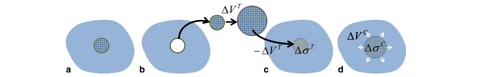
VT are two different definitions of a source volume change. VT is directly obtained under the assumption of a moment tensor for an internal surface character-ized by a displacement gap, and VC is the actual vol-ume change at the source. The difference betweenVT and VC has been discussed by various authors; for a review, see Kumagai et al. (2014). The two volumes are connected with each other through Eshelby’s virtual operation approach (Eshelby 1957) by Aki and Richards (1980, 2002). Figure 1 summarizes this operation. First, the source material is separated by cutting along a closed surface that surrounds the source (Fig. 1a). Then, it is removed from the matrix and undergoes an inelastic (stress-free) deformation byVT (Fig. 1b). The inelasti-cally deformed source volume is elastiinelasti-cally strained and pushed back to its original place: this will generate an additional stress field σT in the source volume and an additional traction is applied on its surface to hold its shape (Fig. 1c). Finally, the source material is welded across the cut surface, and the applied traction is released. Both the source and matrix deform elastically, which results in the source volume change of VC with the elastic stress change fromσT toσC(Fig. 1d).
Eshelby’s approach was originally introduced to obtain the equivalent body force, or the “stress glut,” in the moment tensor representation of a volume source. The stress glut is defined as the difference between the true physical stress and the model stress (Backus and Mulcahy 1976) and has been shown to be equivalent to the moment-density tensor (Backus and Mulcahy 1976; Aki and Richards 1980). In Eshelby’s model, the stress glut is given by the stress σT in the source material after pushed back into its original space under elastic strain (Fig. 1c). Consequently, writing the true stress as σC
(Fig. 1d), the model stress (Backus and Mulcahy 1976) is−(σT−σC), which is tensional in the case shown in Fig. 1.
The actual changes (i.e.,VC and the actual pressure change) are relevant in the fluid mechanical modeling for the source, while the moment tensor representation is directly linked to the effective values (i.e.,VT and the stress glut). Defining the relationship between the actual changes and the moment tensor representation is known to be a potentially confusing problem (Aki and Richards 1980; Aki and Richards 2002). The moment tensor rep-resentation of a spherical volume source in terms of the stress glut, which in this isotropic case is the pressure glutp, was originally given by equation 3.34 of Aki and Richards (1980) as
M= 4π
3 a 3
⎛
⎝0p 0p 00
0 0 p
⎞
⎠, (3)
along with the remark “in the above equation,pshould not be confused with the pressure jump at the spher-ical surface at radius a.” The expression given in (3) was replaced in the second edition of their textbook (equation. 3.35 in Aki and Richards, 2002) by
M=
⎛ ⎝
λ+ 2 3μ
VT 0 0
0 λ+23μVT 0
0 0 λ+23μVT
⎞ ⎠,
(4)
with the comment that “in the above equation, VT is the stress-free volume change and should not be confused with the volume changeVCof a confined source region.” It is commonly accepted that the volume change directly related to the isotropic part (i.e., the trace) of the moment tensor isVT, given by the equation
tr(M)=3
λ+ 2
3μ V
T, (5)
and that VC can be obtained fromVT by Eshelby’s operation. However, it can be difficult to understand the mathematical reasoning underpinning this calcula-tion, because Eshelby’s operation is entirely conceptual
and assumes specific processes for the stress-free volume change, such as phase transition.
Richards and Kim (2005) noted this problem for the case of the moment tensor representation of an underground explosion. The use of the definition ofVT may appeal, since it is associated with a stress-free strain that phe-nomenologically appears to describe the consequences of the explosion in an unconfined volume, which is deter-mined by the explosion yield. In reality, seismic moments differ for explosions having the same charge size placed at different depths. Therefore,VT is not literally a stress-free volume change of the charge excited by the explosion (Richards and Kim 2005). Kumagai et al. (2014) made comprehensive case studies of isotropic volume sources, finding different forms of the relation betweenVT and the source volume changeVCdepending on the source material and geometry.
Here, we present a straightforward explanation of the relationships amongVT,VC, the stress glut, and the actual stress for a general volume source based solely on the representation theorem, which in turn yields the dis-placement field using Green’s function. In the absence of body forces, the displacement field consists of two inte-grals over the source surface: one for surface displacement and the other for surface traction. First, we demonstrate that in contrast to the representation of earthquake shear faulting, the implicit assumption of omitting the surface traction integral, made while deriving the moment tensor, does not hold for a volume source. Second, we introduce a mathematical procedure developed in the boundary-integral equation methods (Altiero and Gavazza 1980) for representing a volume source, which adequately con-siders the traction contribution. The traction correction turns out to be an additional surface displacement in the other surface integral term, causing an “imaginary volume change.” We therefore propose an alternative definition ofVT as the sum ofVC and this imaginary volume change.
Method
A conventional moment tensor representation in seismology
We consider an elastic body with volumeVexand external surfaceSand with internal surfaceof a volume source. The elastic deformation field inVexis produced by the dis-placement and traction exerted on the surfacesandSin the case of a no-body force. The representation theorem gives an expression for the displacementuk in Vex (Aki and Richards, 1980, equation 2.41):
uk(x,t)= −
+S
cijpquinj∗Gkp,qd+
+S
Ti∗Gkid,
(6)
whereGkpis the elastic Green’s function in the medium without the internal surface,Gkp,qis its spatial deriva-tive in theqth direction,cijpqis the elastic constant tensor,
Ti is the traction, and nj is a unit vector normal to the surface and directed outwards fromVex. It is noted that
nj on the internal surface is customarily taken out-wards fromVex. The surface integral onS in (6) can be eliminated if we assume that bothui andGkisatisfy the same homogeneous boundary conditions onS; otherwise, we have to exactly evaluate the integral onS(Kame and Kusakabe 2012). We note thatf∗g=0tf(τ)g(t−τ)dτ =
t
0f(t−τ)g(τ)dτ =
∞
−∞ f(τ)g(t−τ)dτiff(t)andg(t)are zero fort<0 (Aki and Richards 1980). Under the assump-tion of homogeneous boundary condiassump-tions onS, the first and second terms of (6) represent contributions due to the displacement and traction on, respectively.
In the case of a seismic source due to faulting, con-sists of two adjacent surfaces, labeled+and−, which are the opposing faces of the fault, in which case (6) is rewritten as
uk(x,t)=
cijpq[ui]nj∗Gkp,qd−
[Ti]∗Gkid,
(7)
where square brackets are used to denote the difference
between the enclosed values on + and − and the
surface-normal vector onis taken in the direction from
−to+following the convention adopted by Aki and Richards (1980). It is the same direction as the normal vec-tor on−, that is, opposite to the original surface-normal vector on. That is why Eq. (7) has an opposite sign from (6). The continuity of traction across the fault surfaces means that [Ti] is always zero; consequently, (7) reduces to
uk(x,t)=
cijpq[ui]nj∗Gkp,qd, (8)
and the moment-density tensormpqis defined in terms of the displacement discontinuity as
mpq=cijpq[ui]nj. (9)
When a fault planeis effectively regarded as a point source, (8) is approximated by
uk(x,t)=Mpq∗Gkp,q, (10)
Mpq=
mpqd, (11)
whereMpqis the moment tensor.
The elastic tensor for an isotropic body is
cijpq=λδijδpq+μ(δipδjq+δiqδjp), (12)
whereλ andμare Lamé parameters andδij is the Kro-necker symbol. Equation (12) reduces (9) to
Volumetric source representations in seismology
The preceding discussion is not limited to a shear fault but includes opening on the fault, i.e., a displacement dis-continuity oriented perpendicular to the fault surface. Let us now consider the case where a surface= ++− lies on thex3 = 0 plane and the displacement discon-tinuity has a uniform non-zero component solely in the
x3-direction perpendicular to. This source corresponds to an opening crack, and it represents a typical example of a volume source. For (11), the moment tensor represen-tation of a thin crack with an opening dislocation in an isotropic medium is
M=
⎛
⎝λ0 0λ 00 0 0 λ+2μ
⎞
⎠[u3]. (14)
An isotropic volume source may be represented by three perpendicular planar cracks with equal areaand opening [u], given
M=
⎛ ⎝λ+
2
3μ 0 0
0 λ+ 23μ 0
0 0 λ+ 23μ
⎞
⎠(3[u]). (15)
Note that (15) corresponds to (4), if the total opening volume 3[u]is the stress-free volume changeVT.
For the isotropic moment tensor in (15), the 3D static Green’s function directly gives the radial displacement fieldur(x) = uisor (r)as a function of distancerfrom the center of the cracks as follows (Kumagai et al. 2014):
uisor (r)= λ+ 2 3μ λ+2μ
VT
4πr2, (16)
noting that only a radial displacement exists. On the other hand, the analytic displacement field, as obtained for a spherically expanding volume source by Kumagai et al. (2014), is
usolr = V
C
4πr2, (17)
where VC is the actual volume change in the source region.
IfVT in (16) is equal to the spherical volume change
VCin (17), the radial displacementuisor in (16) is smaller thanusolr in (17) and the difference is
usolr −uisor = 4 3μ λ+2μ
VC
4πr2. (18)
Both displacements are identical if we assume
VT = λ+2μ λ+2
3μ
VC, (19)
and this adjustment factor is the same as that convention-ally adopted. In the literature, the adjustment has been explained with reference to Eshelby’s operation (Eshelby 1957) assuming VT is the stress-free volume change
(Aki and Richards 2002). Müller (2001) considered (15) to be true when the isotropic source consists of opening cracks that are homogeneously distributed over the sur-face of a sphere, in which caseVT is the total opening whileVC is the fraction that opens outward. Although it has been acknowledged that the adjustment for a spher-ical volumetric source is correct, a method for obtaining the representation from the seismological moment tensor has not been clearly explained for the general case.
Here, we note that the difference in (19) originates from the second term of (6) that is not included for seismic fault sources. The first and second surface integral terms of (6) respectively give
udisr = λ+ 2 3μ λ+2μ
VC
4πr2, (20)
utrar = 4 3μ λ+2μ
VC
4πr2. (21)
By summingur =udisr +utrar , we directly obtain the ana-lytical solution (17) without adjusting the volume change; the mathematical procedure required to obtain this result is given in the Appendix.
Although both terms of (6) are necessary to fully repre-sent the displacement field with the true boundary condi-tions, it is commonly inconvenient to include two terms in wave analyses. In the following section, we show that using the stress-free volume change, or the stress glut, provides a way of combining the two terms into a single term.
Volume-source representations based on the representation theorem
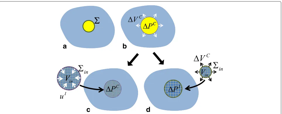
We consider the displacement field due to the expansion of a source cavity bounded by within a surrounding elastic body (see Fig. 3a, b). The displacement field in the elastic body is then represented only by integration on as per (6) with the specified Green’s function, regardless of the material inside the source body. Here, it is assumed that the displacement and the traction onare specified. Note that these quantities are not independent but should obey the elastic equations.
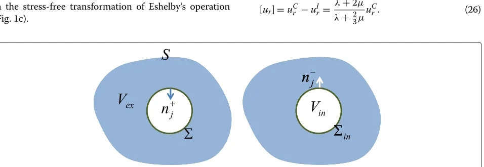
First, we replace the material inside the cavity with an elastic body Vin with surface in that has the same mechanical properties as the surrounding elastic body and the same shape as the cavity. It is assumed that this pro-cedure does not change the boundary conditions onso that the deformation field un is unchanged. The normal vector forinis directed outwards with respect toVin, the opposite direction to that for. The representation (6) may include the surface integral onin:
uk(x,t)= −
+in
cijpquinj ∗Gkp,qd +
+in
Ti ∗Gkid.
Because Vin is composed of the same elastic mate-rial as the external body, the elastic deformation field in
Vin, including the traction and displacement relation on in, satisfies the same elastic equations so that the same Green’s function is applicable on in. Moreover, Betti’s theorem guarantees that
−
in
cijpquinj∗Gkp,qd+
in
Ti∗Gkid=0, (23)
outsideVin. Becauseandinare the same, but oppos-ing, faces of the cavity surface, the integrals on the two surfaces are combined in the same way as (7), giving
uk(x,t)=
cijpq[ui]nj∗Gkp,qd−
[Ti]∗Gkid,
(24)
where the direction of the surface-normal vector onis replaced byn−j that is directed frominto(Fig. 2) fol-lowing Aki and Richards (1980) as in Eq. (7). Adequately taking [ui] and [Ti] allows the displacement field to be represented either by the first or the second integral term on the right-hand side of Eq. (24), which is the so-called indirect boundary-integral equation method (Altiero and Gavazza 1980).
When the bodyVinis subject to the same surface trac-tionTiCon its surfaceinas that on, the term with [Ti] vanishes in (24) and we obtain the same representation as (8). The elastic displacement oninis not the same as that onbut is the value bringingVinfrom zero traction to the given traction by elastic deformation (Fig. 3c). Therefore, the displacement discontinuity [ui] in (8) is interpreted as the difference between the actual displacementuCi on the cavity wall and the imaginary displacementuIi onin required to replace the traction term. It is also noted that [ui] corresponds to the difference between the surface of
Vin in the stress-free condition and the original size of the cavity and is therefore equivalent to the displacement in the stress-free transformation of Eshelby’s operation (Fig. 1c).
Alternatively, we may eliminate the displacement term and keep the traction term in (24). In this case, we replace the material inside the cavity with an elastic bodyVinwith surfaceinthat has the same mechanical properties as the surrounding elastic body and the same shape as the cav-ity. The surface displacement oninis assumed to beuCi as that on(Fig. 3d). The deformation ofVinunder this boundary condition should satisfy the elastic equations as in the previous case. The surface traction on in is then different fromTiC. Rather than (8), we may instead represent the solution by
uk(x,t)= −
[Ti]∗Gkid. (25)
The stress discontinuity [Ti] is the difference between the actual traction on the cavity wallTiCand the imaginary tractionTiI that is required to replace the displacement term in (24). BecauseTiC −TiI = TiC +(−TiI), [Ti] has an additional traction−TiIthat is equivalent to the defor-mation ofVinby−uCi . Therefore, [Ti] corresponds to the traction of the state shown in Fig. 1c in Eshelby’s opera-tion. Putting [Ti]= −(τijnj), Eq. (25) is equivalent with equation (3.26) of Aki and Richards (1980) withτijbeing the stress glut of Backus and Mulcahy (1976).
Our interpretation can be illustrated well using a sim-ple analytic problem. Consider the case where the cavity is a sphere with radiusRand volumeV = 43πR3, filled by fluid with an overpressurePC. The corresponding sur-face displacement of the cavity is directed radially outward withuCr =RPC/(4μ), and the volume change isVC=
VPC/(43μ)(Kumagai et al. 2014). On the other hand, the displacement oninfor the same overpressure is directed radially inward with 4πR2uI
r = −VPC/(λ+ 23μ), giving uIr = −4μuCr/(3λ+2μ). The displacement gap used in the moment tensor is then
[ur]=uCr −uIr =
λ+2μ
λ+ 2 3μ
uCr. (26)
Fig. 2A schematic illustration of the normal vectors.n+j andnj−on the internal surfacesandin, respectively.Vexis the elastic medium of
Fig. 3Schematic illustration of our new interpretation: expansion fromatobbyVCdue to the overpressurePCin the fluid cavity bounded by drives the process.cThe internal fluid is replaced by an elastic bodyVinconsisting of the same elastic material as the external medium.Vinhas the same traction oninas the actual overpressure. The corresponding displacement oninisuIi, which is different from the actual displacement on.
dThe internal fluid is replaced by an elastic bodyVinconsisting of the same elastic material as the external medium. A displacement identical to the actual displacement on(b) is applied toVin. The pressure change inVin is thenPI, which differs fromPC
If we assume [ur] as the surface displacement, the cor-responding volume change is
4πR2[ur]= λ+ 2μ
λ+ 2 3μ
VC, (27)
which is equal to Eshelby’s stress-free volume change
VT in (19). Alternatively, if the same outward displace-ment uCr is applied to the inner sphere surface in, the corresponding stress field in Vin is a negative pressure defined as
PI= −
λ+2 3μ
3uCr R = −
λ+ 2 3μ
VC V ,
(28)
and therefore,
[Ti]=
PC−PI
ni=(λ+2μ)V C
V ni=
λ+2 3μ
VT V ni.
(29)
Results and discussion A unified explanation
Here, we have shown the difference of the effective changes (i.e., VT and the stress glut) from the actual changes (i.e., VC and the actual pressure change) as a consequence of reducing the two surface integral terms in the representation (6) to one term as either (8) or (25). This reduction is done by replacing the surface dis-placement withuCi −uIi or replacing the surface traction withTiC−TiI, respectively, which has already been shown
by Altiero and Gavazza (1980) as the indirect boundary-integral methods. Here, we make a link between their formulation and the moment tensor representation of a volume source. Given that the stress giving the traction
TiC−TiIcorresponds to the so-called stress glut, we pro-pose calling uCi − uIi the “displacement glut,” which is equivalent to Eshelby’s stress-free transformation of Aki and Richards (2002) and to the spherical-crack opening of Müller (2001). We consider the term “displacement glut” to be more appropriate because it is not linked to specific processes such as the stress-free transformation or spherical-crack models and because it makes a logical counterpart to the stress glut. Moreover, the representa-tion in terms of the displacement glut, rather than stress glut, is more useful because the seismic moment ten-sor inversion framework has been developed in the form of (8).
The present work generalizes the conclusion of Kumagai et al. (2014) for a bimaterial spherical source. In calcu-lating the displacement glut or stress glut, it should be assumed that the internal body has the same elastic prop-erties as the external body, regardless of the actual internal material. This understanding does not necessarily help in the interpretation of a moment tensor in terms of the physical source process, but it is useful for forward mod-eling from the source process to the equivalent moment tensor. When a source geometry is defined andTiC oruCi
of the external elastic body. This calculation can be per-formed for arbitrary geometries. The distribution of [ui] on the surface can then be obtained, and the moment-density tensor calculated by (9). Finally, the moment tensor of the equivalent point source is obtained by inte-grating the moment-density tensor over the source surface as in (11). This calculation can be performed using either numerical or analytical methods.
Conclusion
This work presents a comprehensive explanation as to why VT, rather than VC, appears in the moment tensor representation of a volumetric source. We math-ematically redefineVT as the result of a displacement glut, instead of Eshelby’s stress-free volume change con-cept. The difference between the displacement glut and the actual displacement of the source surface replaces the contribution of the traction surface integral term in the representation theorem, which has not previously been used in seismology. With this understanding, we can more confidently link the moment tensor representation with fluid mechanical modeling.
Appendix
Representation theorem for a spherical displacement field
We consider the static displacement field due to the expansion of a spherical cavity in an unbounded, isotropic, and homogeneous medium. The initial radius of the sphere isR. The origin of the spatial coordinate system is defined as the center of the sphere.
Green’s function depends on the distanceLbetween the source atξ and the observation point atx:
Gkp(L)=
In the static case, the representation given by (6) can be rewritten:
For clarity, in the following, we omit the dependence on the spatial variables where they are obvious from the context.
The first term is rewritten using (12) and separated into an isotropic partuKuk and a non-isotropic partuμku:
The second term is represented byuTk:
uTk =
TiGkid(ξ). (37)
Let both the displacement and traction on the sphere surface be directed radially outwards with magnitude
RandP, respectively:
ui(ξ)= −Rni, (38)
Ti(ξ)= −Pni, (39)
whereniis the unit vector normal to the surface, pointing outwards from the elastic medium, i.e., into the sphere. We note that
VC =4πR2R (40)
and, according to the relation of linear elasticity,
P=4μR
R . (41)
Using the boundary conditions (38) and (39), Eqs. (35)– (37) are rewritten as
uKuk =KR
We first evaluate (44) using Green’s function (30):
uTk = −P
the sphere, the surface integral in (45) is converted into a volume integral over the sphereVs, becoming
uTk = P
Because the displacement field is spherically symmetric and non-directional, we may assumex=(0, 0,x)(x>0). Representingξ in a polar coordinate system, we haveL=
Evaluating this integral, we obtain
uTk = −P
Recalling thatxrepresents|x| =rand the definition of
Dxfrom (31), we have
Using (32) and (39), finally, we obtain the radial displace-ment in the same form as (21)
uTk =
wherexk/ris a unit vector in the radial direction.
The isotropic part of the displacement term
Equation (42) is calculated in a similar way as in the previous section:
Using a polar coordinate system and assuming x =
(0, 0,x)(x>0), we have
The partial differentiation of (54) in (53) is conducted in the same way as in the previous subsection. Converting
RtoVCusing (40) and using the definition ofK(35),
The above expression for uKuk gives the radial dis-placement in the same form as (20). In the following section, the remaining term uμku from (43) is shown to vanish.
The non-isotropic part of the displacement term
The values obtained for the first and second terms of the integrand in (43) are denoted as uμku1 and uμku2, respectively. The calculation of the latter follows the method outlined in the previous section, and it is obvious that
the calculation of the first term is more complicated and is presented below.
For mathematical convenience, the variable of partial
Returning to polar coordinates, we have d =
R202πdφ0πdθsinθ. We letx=(0, 0,x) (x>0), and
As in (54), we also representLin polar coordinates, from which we obtain
Substituting (61) and (62) into (58) and (60), and conduct-ing the integration with respect toφ, we obtain
A= R From the definition ofL, we have
cosθ = L
and (64) reduces to
Bk=
We note that the solution outside the sphere is obtained when|x−R| =x−Rin (66) and (67), while that inside the sphere is obtained when|x−R| = −x+R.
Evaluating the algebra and integration with respect toL
in (66) and (67), we obtain
Referring back to (51), the partial differentiation is per-formed as follows:
The other partial derivative term vanishes, as
∂2
Combining (72) and (73), we finally obtain
uμku1= 2
The authors have no competing interests to declare.
Authors’ contributions
All the authors contributed to discussions clarifying the theory presented in this manuscript. MI presented the idea for the new interpretation. TK solved the problem for the spherical case presented in the Appendix. NK and TK verified the mathematical consistency of the new interpretation in the representation theorem. All authors read and approved the final manuscript.
Acknowledgements
for valuable discussions and suggestions. M.I. was supported by JSPS (KAKENHI 24234567), T.K. was supported by a Grant-in-Aid from JSPS (No. 25-7419), and N.K. was supported by JSPS (KAKENHI 25400441). This work was also supported by MEXT of Japan via the Program for Leading Graduate Schools and by the Earthquake and Volcano Hazards Observation and Research Program.
Author details
1Earthquake Research Institute, The University of Tokyo, Yayoi, Bunkyo-ku, Tokyo 113-0032, Japan.2Graduate School of Environmental Studies, Nagoya University, Chikusa-ku, Nagoya 464-8601, Japan.
Received: 10 September 2015 Accepted: 12 January 2016
References
Aki K, Richards PG (1980) Quantitative seismology: theory and methods. First Ed. W. H. Freeman, San Francisco
Aki, K, Richards PG (2002) Quantitative seismology. 2nd Edn. University Science Books, Sausalito
Altiero NJ, Gavazza SD (1980) On a unified boundary-integral equation method. J Elasticity 10:1–9
Amoruso A, Crescentini L (2009) Shape and volume change of pressurized ellipsoidal cavities from deformation and seismic data. J Geophys Res 114:B02210. doi:10.1029/2008JB005946
Ampuero JP, Dahlen FA (2005) Ambiguity of the moment tensor. Bull Seism Soc Am 95(2):390–400. doi:10.1785/0120040103
Backus G, Mulcahy M (1976) Moment tensors and other phenomenological descriptions of seismic sources - I. continuous displacements. Geophys J R astr Soc 46:341–361
Chouet BA (1996) New methods and future trends in seismological volcano monitoring. In: Monitoring and mitigation of volcano hazards. Springer, Berlin. pp 23–97
Davis PM (1986) Surface deformation due to inflation of an arbitrarily oriented triaxial ellipsoidal cavity in an elastic half-space, with reference to Kilauea Volcano. Hawaii J Goephys Res 91(B7):7429–7438
Eshelby JD (1957) The determination of the elastic field of an ellipsoidal inclusion and related problems. Proc R Soc London, Ser A 241:376–396 Ichihara M (2008) Dynamics of a spherical viscoelastic shell: implications to a
criterion for fragmentation/expansion of bubbly magma. Earth Planet Sci Lett 265:18–21
Kame N, Kusakabe T (2012) Proposal of extended boundary integral equation method for rupture dynamics interacting with medium interfaces. J Appl Mech 79(031017). doi:10.1115/1.4005899
Kazahaya R, Mori T, Takeo M, Ohminato T, Urabe T, Maeda Y (2011) Relation between single very long period pulses and volcanic gas emissions at Mt. Asama, Japan. Goephys Res Lett 105(B8):19,135–19,147
Kumagai H, Maeda Y, Ichihara M, Kame N, Kusakabe T (2014) Seismic moment and volume change of a spherical source. Earth Planet Space 66(7). doi:10.1186/1880-5981-66-7
Maeda Y, Takeo M (2011) Very-long-period pulses at Asama volcano, central Japan, inferred from dense seismic observations. Goephys J Int 185(1):265–282. doi:10.1111/j.1365-246X.2011.04938.x
Mizuno N, Ichihara M, Kame N (2015) Moment tensors associated with expansion and movement of fluid in ellipsoidal cavities. J Geophys Res. in press
Müller G (2001) Volume change of seismic sources from moment tensors. Bull Seism Soc Am 91:880–884
Nishimura T, Nakamichi H, Tanaka S, Sato M, Kobayashi T, Ueki S, Hamaguchi H, Ohtake M, Sato H (2000) Source process of very long period seismic events associated with the 1998 activity of Iwate Volcano, northeastern Japan. J Goephys Res 38:L11307. doi:10.1029/2011GL047555
Richards PG, Kim W-Y (2005) Equivalent volume sources for explosions at depth: theory and observations. Bull Seism Soc Am 95(2):401–407. doi:10.1785/0120040034
Wielandt E (2003) On the relationship between seismic moment and source volume. http://www.software-for-seismometry.de/textfiles/
TheoreticalSeismology/volsource.ps
Submit your manuscript to a
journal and benefi t from:
7 Convenient online submission 7 Rigorous peer review
7 Immediate publication on acceptance 7 Open access: articles freely available online 7 High visibility within the fi eld
7 Retaining the copyright to your article