Sonic Watermarking
Ryuki Tachibana
Tokyo Research Laboratory, IBM Japan, 1623-14 Shimotsuruma, Yamato-shi, Kanagawa-ken 242-8502, Japan Email:[email protected]
Received 5 September 2003; Revised 8 January 2004; Recommended for Publication by Ioannis Pitas
Audio watermarking has been used mainly for digital sound. In this paper, we extend the range of its applications to live perfor-mances with a new composition method for real-time audio watermarking. Sonic watermarking mixes the sound of the watermark signal and the host sound in the air to detect illegal music recordings recorded from auditoriums. We propose an audio watermark-ing algorithm for sonic watermarkwatermark-ing that increases the magnitudes of the host signal only in segmented areas pseudorandomly chosen in the time-frequency plane. The result of a MUSHRA subjective listening test assesses the acoustic quality of the method in the range of “excellent quality.” The robustness is dependent on the type of music samples. For popular and orchestral music, a watermark can be stably detected from music samples that have been sonic-watermarked and then once compressed in an MPEG 1 layer 3 file.
Keywords and phrases:sonic watermarking, audio watermarking, real-time embedding, live performance, bootleg recording, copyright protection.
1. INTRODUCTION
A digital audio watermark has been proposed as a means to identify the owner or distributor of digital audio data
[1,2,3,4]. Proposed applications of audio watermarks are
copyright management, annotation, authentication, broad-cast monitoring, and tamper proofing. For these purposes, the transparency, data payload, reliability, and robustness of audio watermarking technologies have been improved by a number of researchers. Recently, several audio watermarking techniques that work by modifying magnitudes in the fre-quency domain were proposed to achieve robustness against distortions such as time scale modification and pitch shifting
[5,6,7].
Of the various applications, the primary driving forces for audio watermarking research have been the copy con-trol of digital music and searching for illegally copied dig-ital music, as can be seen in The Secure Digdig-ital
Mu-sic Initiative (http://www.sdmi.org/) and the Japanese
So-ciety for the Rights of Authors, Composers and Pub-lishers (Final selection of technology toward the global
spread of digital audio watermarks,http://www.jasrac.or.jp/
ejhp/release/2000/1006.html, October 2001). In these usages, it is natural to consider that an original music sample, which is the target of watermark embedding, exists as a file stored digitally on a computer. However, music is performed,
cre-ated, stored, and listened to in many different ways, and it is
much more common that music is not stored as a digital file on a computer.
Earlier research [8] proposed various composition
meth-ods for real-time watermark embedding and showed how they can extend the range of applications of audio water-marks. In a proposed composition method named “analog watermarking,” a trusted conventional analog mixer is used to mix the host signal (HS) and the watermark signal (WS) after the WS is generated by a computer and converted to an analog signal. This composition method makes it unnec-essary to convert the analog HS to a digital signal, since the conversion results in a risk of interrupting and delaying the playback of the HS.
At the same time, another composition method named “sonic watermarking” was proposed. This composition method mixes the sound of the WS and the host sound in the air so that the watermark can be detected from a recording of
the mixed sound. The method will allow searching for
boot-leg recordingson the Internet, that is, illegal music files that have been recorded in auditoriums by untrustworthy audi-ence members using portable recording devices. The record-ings are sometimes burned on audio CDs and even sold at shops, or distributed via the Internet. Countermeasures, such as examining the audience members’ personal belongings at auditorium entrances, have been used for decades to cope with this problem. The ease of distribution in the broad-band Internet has increased the problem of bootleg record-ings. For movies, applications of video watermarking to dig-ital cinema have been gathering increasing attention recently
[9,10]. One of the purposes is to prevent ahandy cam attack,
Uploading
Figure1: Sonic watermarking to detect bootleg recordings on the Internet. The watermark sound and the host sound are mixed in the air.
neither digital watermarking, encryption, nor streaming can
be used inliveperformances, so there has been no efficient
means to protect the copyrights of live performances in the Internet era.
In this paper, we carefully consider the application model and the possible problems of sonic watermarking, which was
briefly proposed in [8], and report the results of intensive
ro-bustness tests and a multiple stimulus with hidden reference
and anchors [11] (MUSHRA) subjective listening test which
we performed to investigate the effects of critical factors of
sonic watermarking, such as the delay and the distance be-tween the sound sources of the HS and the WS.
The paper is organized as follows. InSection 2, we
de-scribe the usage scenario of sonic watermarking. Some pos-sible problems limiting the use of sonic watermarking are
listed in Section 3. In Section 4, we describe a
watermark-ing algorithm that is designed to solve some of the prob-lems. The acoustic quality of the algorithm is assessed by
a subjective listening test described in Section 5. The
ro-bustness of the algorithm is shown by experimental results in Section 6. InSection 7, we present some concluding re-marks.
2. SONIC WATERMARKING
In sonic watermarking, the watermark sound generated by a watermark generator is mixed with the host sound in the
air (Figure 1). A watermark generator is a device that is
equipped with a microphone, a speaker, and a computer. The host sound is captured using the microphone, the computer calculates the WS, and the WS enters the air from the speaker. The reason that the computer needs to be fed the host sound
is to calculate the frequency masking effect [12] of the host
sound. The lifecycle of a bootleg recording containing sonic
watermarks is illustrated inFigure 2. While broken lines with
arrowheads indicate sonic propagation, the solid lines indi-cate wired analog transmissions or digital file transfers. For example, the untrustworthy audience member may compress
Searching + Watermark detection Computer
Figure 2: The lifecycle of a bootleg recording with sonic water-marks. While broken lines with arrowheads indicate sonic propa-gation, solid lines indicate wired analog transmissions or digital file transfers.
the bootleg recording as an MP31file and upload it to the
In-ternet. They may attack the sonic watermarking before com-pression. The recording device may be an analog cassette tape recorder, an MP3 recorder, a minidisc recorder, and so forth. Note that sonic watermarking is not necessary in live per-formances where the sound of the musical instruments and the performers are mixed and amplified using analog
elec-tronic devices. Analog watermarking [8] can be used instead.
3. PROBLEMS
In this section, we classify the possible problems that may limit the use of sonic watermarking into three major cat-egories: (1) real-time embedding, (2) robustness, and (3) acoustic quality. Though all of the other problems of digital audio watermarking are also problems of sonic watermark-ing, they are not listed here.
3.1. Problems related to real-time embedding
The major problems related to real-time embedding are the performance of the watermark embedding process and the delay of the WS.
(1)Performance. Watermark embedding faster than real-time is the minimum condition for sonic watermarking. The computational load of the watermark generator must be kept low enough for stable real-time production of the WS. A wa-termark embedding algorithm faster than real-time was also
reported by [14].
(2) Delay.Even when the watermark generator works in real-time, the watermark sound will be delayed relative to the host sound. We will discuss the problems of robustness and acoustic quality caused by the delay in later sections.
The delay consists of a prerecording delay and a delay in-side the watermark generator. The prerecording delay is the
Total delay
Time Recording point Playing point
Sound card (out) Playback buffers
Watermark signal buffer Watermark calculation
Host signal buffer Recording buffer
Sound card (in)
Figure 3: A watermark signal is delayed relative to a host signal because of the recording buffers, watermark calculations, and play-back buffers.
time required for the sound to propagate from the source of the host sound to the microphone of the watermark genera-tor. For example, when the distance is 5 m, the prerecording delay will be approximately 15 milliseconds.
The delay inside the watermark generator is caused by
the recording buffers, playback buffers, and WS calculations
(Figure 3). Though the length of the playback buffers and the
recording buffers can be reduced using technologies, such as
ASIO2software and hardware, it is impossible to reduce them
to zero. The WS calculation causes two kinds of delay. The first is that it is necessary to store a discrete Fourier transform (DFT) frame of the HS to calculate its power spectrums. The second is the elapsed time for the WS calculation.
3.2. Robustness
Possible causes interfering with successful detection can be roughly categorized into (1) deteriorations after recording and (2) deteriorations before and during recording by the untrustworthy audience member. After recording, the un-trustworthy audience member may try to delete the water-mark from the bootleg recording. The possible attacks in-clude compression, analog conversion, trimming, pitch shift-ing, random sample croppshift-ing, and so forth. As for deteriora-tions before and during recording, the following items have to be considered.
(1)Delay of the watermark signal. When the WS is layed, the phase of the HS drastically changes during the de-lay, so the phases of the HS and the WS become almost in-dependent. Watermarking algorithms assuming perfect
syn-chronization of the phases suffer serious damage from the
delay.
(2) Reverberations. Reverberations of the auditorium must be mixed into the host sound and the watermark sound.
(3) Noises made by audience. Noises made by sources other than the musical instruments become disturbing
fac-2ASIO is the Steinberg audio stream input/output architecture for low latency high performance audio handling.
tors for watermark detection. Such sounds include voices and applause from audience members and rustling noises made by hands touching the recording device. If microphones di-rected towards the audience record the loud noise of the au-dience, and if the watermark generator utilizes the masking
effect of the audience noise as well, detection of the
water-mark will be easier. However, since it is impossible to record noises that are made near widely scattered portable recording devices, the noise inevitably interferes with watermark detec-tion.
(4) Multiple watermark generators. In some cases, ar-rangements using multiple watermark generators would be
better to reflect the actual masking effects of each
audi-ence member. When using multiple watermark generators, it would be also necessary to consider their mutual interfer-ence.
3.3. Acoustic quality
There are several factors that may make the acoustic quality of sonic watermarking worse than that of digital audio wa-termarking.
(1) Strength of the watermark signal. Because the effi -ciency of watermark embedding is worse and more severe deterioration is expected in the sound than for digital audio watermarking, the WS must be relatively louder than a digital audio watermark. This results in lower acoustic quality.
(2)Delay of the watermark signal.An example would be when the host sound includes a drumbeat that abruptly di-minishes, and the delayed watermark sound stands out from the host sound and results in worse acoustic quality. There
is a “postmasking effect” that occurs after the masker
dimin-ishes [12]. For the first 5 milliseconds after the masker
di-minishes, the amount of the postmasking effect is as high as
simultaneous masking. After the 5 milliseconds, it starts an almost exponential decay with a time constant of 10 millisec-onds. Therefore, if the delay of the watermark sound is short
enough, the postmasking effect is expected to mask the
wa-termark sound. However, the longer the delay, the more the host sound changes, and the weaker the masking from the
postmasking effect.
(3)Differences of the masker.The HS captured by the
mi-crophone of the watermark generator is different from the
host sound that the audience listens to. Hence, the masking
effect calculated by the generator will also be different from
the actual masking effect as heard by the audience.
(4) Different locations of the sound sources. While the sources of the host sound may be spread around the audi-torium stage, the sources of the watermark sound must be limited to a few locations, even if multiple watermark
genera-tors are used. The difference in the direction and the distance
of the sources of the watermark sound and the host sound
from each audience member will have a negative effect on
the acoustic quality.
4. ALGORITHMS
(a) (b)
Figure4: (b) is an enlargement of a part of (a). A pattern block consists of tiles. The embedding algorithm modifies magnitudes in the tiles according to pseudorandom numbers. The numbers in the figure are examples of the pseudorandom values.
processings such as geometric distortions of the audio
sig-nal was proposed in [6,15]. Since the algorithm is not
ap-plicable to sonic watermarking because of the delay of the WS, we altered the embedding algorithm. If the same values of parameters were used, the same previous detection algo-rithm can detect the watermark from the content, whether the previous algorithm or the modified algorithm is used for watermarking. However, because this is the first intensive ex-periments of sonic watermarking, more priority was given to the basic robustness against sonic propagation and noise ad-dition than to the robustness against geometric distortion.
Therefore, different parameter values from [15] were used
in the experiments, and robustness against geometric distor-tions was not tested.
4.1. Basic concepts
The method can be summarized as follows. The method em-beds a multiple-bit message in the content by dividing it into short messages and embedding each of them together
with a synchronization signal in a pattern block. The
syn-chronization signal is an additional bit whose value is al-ways 1. The pattern block is defined as a two-dimensional segmented area in the time-frequency plane of the content (Figure 4a), which is constructed from the sequence of power spectrums calculated using short-term DFTs. A pattern block
is further divided intotiles. We call the tiles in row asubband.
A tile consists of four consecutive overlapping DFT frames. A pseudorandom number is selected corresponding to each tile (Figure 4b). We denote the value of the pseudorandom
num-ber assigned to the tile at thebth subband in thetth frame
byωt,b, which is +1 or−1. The previous algorithm decreased
the magnitudes of the HS in the tiles assigned−1 (Figure 5b).
However, because it is impossible to decrease the magnitudes of the HS in the case of sonic watermarking, the proposed
algorithm makes the WS zero in those tiles (Figure 5d). For
the tiles with a positive sign, the magnitudes and the phases of the WS are given as in the previous method. However, be-cause of the delay, to give the WS the same phases as the HS
at the computer has almost the same effect as giving the WS
a random phase (Figure 5c).
Figure5: The host signal and the watermark signal (a) and (b) for the previous method and (c) and (d) for the proposed method.
We denote the value of the bit assigned to the tile byBt,b,
which is 1 or 0. The values of the pseudorandom numbers and the tile assignments of the bits are determined by a sym-metric key shared by the embedder and the detector.
4.2. Watermark generation
The watermark generation algorithm calculates the complex
spectrum,ct,f, of the fth frequency bin in thetth frame of
a pattern block of the content by using the DFT analysis of a frame of the content. We denote the magnitude and the phase
of the bin byat,f andθt,f, respectively. Then the algorithm
calculates the inaudible level of the magnitude modification by using a psychoacoustic model based on the complex
spec-trum. We indicate this amount of the fth frequency of the
tth frame in a pattern block bypt,f. We use this amount for
the magnitude in the fth frequency bin of the WS.
A sign,st,b, which determines whether to increase or leave
unchanged the magnitudes of the HS in a tile is calculated
from the pseudorandom value,ωt,b, the bit value,Bt,b, and
the location,t, of the frame in the block. If the frame is in
the first two frames of a row of tiles, that is, if the remainder
of dividing tby 4 is less than 2, thenst,b = ωt,b(2Bt,b−1).
Otherwisest,b= −ωt,b(2Bt,b−1). This is because, by
embed-ding opposite signs in the first and last two frames of a tile
and by detecting the watermark using the difference of the
magnitudes, cancellation of the HS can make the detection
robust. In the tiles where the calculated sign,st,b, is positive,
the phase of the HS,θt,f, is used for the phase,φt,f, in the fth
frequency bin of the WS, while we assume the fth frequency
is in the bth subband. In the tiles with a negative sign, the
magnitudept,f and the phaseφt,f is set to zero. At this point
in the procedure, the magnitudept,fand the phaseφt,f of the
WS have been calculated. The WS is converted to the time domain using inverse DFTs.
This procedure increases the magnitudes of the HS by
pt,f only in the tiles with a positive sign. This change makes
the power distribution of the content nonuniform, and hence
makes detection possible. However, because the efficiency of
magnitude modification is much worse than in the previous algorithm, a decrease of the detected watermark strength is inevitable. It is necessary to use a stronger WS than that the previous method uses.
4.2.1. Psychoacoustic model
The ISO-MPEG 1 audio psychoacoustic model 2 for layer 3
the experiments, with some alterations:
(i) an absolute threshold was not used for these experi-ments. We believe this is not suitable for practical wa-termarking because it depends on the listening volume and is too small in the frequencies used for watermark-ing,
(ii) a local minimum of masking values within each fre-quency subband was used for all frefre-quency bins in the subband. Excessive changes to the WS magnitudes do not contribute to the watermark strength, and they also lower the acoustic quality by increasing the WS,
(iii) a 512-sample frame, 256-sample IBLEN,3 and a sine
window were used for the DFT for the psychoacoustic analysis to reduce the computational cost.
Due to the postmasking effect, a shorter DFT frame is
ex-pected to result in better acoustic quality, because of the shorter delay. However, the poor frequency resolution caused by a too short DFT frame reduces the detected watermark strength. This is the reason a 512-sample DFT frame was se-lected for the implementation.
4.3. Watermark detection
The detection algorithm calculates the magnitudes of the content for all tiles and correlates these magnitudes with the pseudorandom array.
The magnitudeat,f of the fth frequency in thetth frame
of a pattern block of the content is calculated by the DFT analysis of a frame of the content. A frame overlaps the adja-cent frames by a half window. The magnitudes are then nor-malized by the average of the magnitudes in the frame. We
denote a normalized magnitude by at,f. The difference
be-tween the logarithmic magnitudes of a frame and the next
nonoverlapping frame is taken asPt,f =logat,f −logat,f+2.
The magnitudeQt,bof a tile located at thebth subband of the
tth frame in the block is calculated by averaging thePt,fs in
the tile. The detected watermark strength for the jth bit in
the tile is calculated as the cross-correlation of the pseudo-random numbers and the normalized magnitudes of the tiles by
lated for the tiles assigned for the bit. Similarly, the synchro-nization strength is calculated for the synchrosynchro-nization signal. The watermark strength for a bit is calculated after synchro-nizing to the first frame of the block. The synchronization process consists of a global synchronization and a local ad-justment. In the global synchronization, assuming that cor-rect synchronization positions of several consecutive blocks
3IBLEN is a length parameter used by the MPEG 1 psychoacoustic model [13]. The analysis window for the psychoacoustic calculation process is shifted by IBLEN for each FFT.
are separated by the same number of frames, the synchro-nization strengths detected from blocks that are separated by the same number of frames are summed up, and the frame that gives the maximum summed synchronization strength is chosen. In the local adjustment, the frame with the lo-cally maximum synchronization strength is chosen from a
few neighboring frames. In [15], the synchronization process
is described in more detail.
4.4. Implementation
We implemented a watermark generator that can generate sonic watermarks in real time and a detector that can detect 64-bit messages in 30-second pieces of music A Pentium IV
2.2 GHz Windows XP PC equipped with a Sound Blaster
Au-digy Platinum sound card by Creative Technology, Ltd. was used for the platform. The message is encoded in 448 bits by adding 8 cyclic redundancy check (CRC) parity bits, using turbo coding, and repeating it twice. Each pattern block has 3 bits and a synchronization signal embedded, and the block has 24 columns and 8 rows of tiles. Each of the 24 frequency subbands is given an equal bandwidth of 6 frequency bins. The frequency of the highest bin used is 12.7 kHz. The length of a DFT frame is 512 samples to shorten the delay. Based on the psychoacoustic model, the root mean square power of the
WS is 23.0 dB lower than that of the HS on average.
Exam-ples of watermark signals generated for a popular song and a
trumpet solo are shown inFigure 6.
At the time of detection, while 48 tiles out of the 192 tiles are dedicated to the local adjustment of the pattern block synchronization, the tiles assigned for the bits are also used for the global synchronization. For the global synchroniza-tion, it is assumed that 16 consecutive blocks have consistent synchronization positions. The false alarm error ratio is
the-oretically under 10−5, based on the threshold of the square
means of the detected bit strengths. Another threshold on the estimated watermark SNR is set to keep the code word
error ratio under 10−5. The reasons to use both thresholds
are described in [16].
4.4.1. Delay
The delay of the WS was approximately 17.8 milliseconds in total. The details are as follows. A total of 128 samples for
both the playback buffer and the recording buffer were
re-quired for stable real-time watermark generation. The length of a DFT frame was 512 samples. The watermark calcula-tion process took approximately 3.1% of the playback time. Since the length of a DFT frame was 512 samples, the elapsed time for the WS calculation corresponds approximately to the playback time for 16 samples. Hence, the total delay was
128 + 128 + 512 + 16=784 samples, which was about 17.8
milliseconds for 44.1 kHz sampling.
5. ACOUSTIC QUALITY
The evaluation of the subjective audio quality of the
algo-rithm was done by a MUSHRA [11] listening test. The
14
Figure6: Examples of the watermark signal and the corresponding host signal for (a) a popular song and (b) a trumpet solo.
Table1: The test samples for the listening tests.
Sample Duration Category Description
is1 8 s Solo Castanets
is2 10 s Solo Glockenspiel
is3 12 s Solo Guitar
is4 14 s Solo Trumpet
io1 15 s Orchestra Soloists and orchestra
io2 12 s Orchestra Wind ensemble
ip1 16 s Popular Eddie Rabbitt
ip2 13 s Popular Michael Jackson
ip3 12 s Popular Mai Kuraki
investigated. Those are (1) the delay of the WS relative to the HS and (2) the angle between the sound sources of the WS and the HS (as measured from the listener’s location).
The test samples were monaural excerpts from popular music, orchestral music, and instrumental solos as described inTable 1. The mean duration of the samples was 12.3 sec-onds. All of the test signals were sampled at a frequency of
44.1 kHz and with a bit resolution of 16 bits. All of them were
upsampled to 48 kHz before the test to adjust to the listen-ing equipment. Though most of the 18 subjects were inexpe-rienced listeners, there were training sessions in advance of the test in which they were exposed to the full range and na-ture of all of the test signals. To give anchors for comparison, the subjects were also required to assess the audio quality of
hidden references (hr),47 kHz lowpass filtered samples (al7),
and samples which had been compressed in MP3 files with a bit rate of 48 kbps (am48) or 64 kbps (am64) for a monaural channel using the Fraunhofer codec of Musicmatch Jukebox 7.20. The references (r), the hidden references, and the
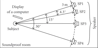
an-chors were played by the speaker SP1 (Figure 7). The other
test signals (Table 2) were as described below.
4Though the test signals of the hidden references were identical to the reference signals, the subjects were required to assess their quality without knowing which were which.
Speak
Figure7: The listening environment for the MUSHRA subjective
listening tests. Three speakers, SP2, SP3, and SP4, were at offsets from the direction of SP1 by 4.3◦, 15◦, and 30◦, respectively.
(i)sd10 sonic watermark with a delay of 10 milliseconds.
While the HS completely identical to the reference was played from SP1, a WS that had been computed in advance based on the HS was simultaneously played from another speaker,
SP2, with a delay of 10 milliseconds. SP2 was offset from the
direction of SP1 by 4.3◦. The subjects listened to the mixed
sound of the HS and the WS.
(ii)sd20 sonic watermark with a delay of 20 milliseconds.
The same WS used for sd10 was played from SP2 with a delay of 20 milliseconds, which is close to the delay of our imple-mentation.
(iii)sd40 sonic watermark with a delay of 40 milliseconds.
The WS was played from SP2 with a delay of 40 milliseconds. (iv)sa15 sonic watermark with an angle of 15◦.The WS was played from another speaker, SP3, with a delay of 20
mil-liseconds. SP3 was offset 15◦from SP1.
(v)sa30 sonic watermark with an angle of 30◦.The WS was played from another speaker, SP4, with a delay of 20
millisec-onds. SP4 was offset 30◦from SP1.
5.1. Results
The mean and 95% confidence interval of the subjective
acoustic quality of the test signals are shown in Figure 8.
Table2: The test signals for the listening tests. SP1, SP2, SP3, and SP4 are the speakers illustrated inFigure 7. Monaural signals simul-taneously played from the speakers are listed in this table. The ab-breviations are explained inTable 3.
Signal SP1 SP2 SP3 SP4
r REF – – –
Table3: Description of the abbreviations used inTable 2.
Abbreviation Description
REF Reference monaural signal
MP364 Compressed signal using MP3 64 kbps MP348 Compressed signal using MP3 48 kbps LP7 7 kHz lowpass filtered signal
WD10 Watermark signal with 10 milliseconds delay WD20 Watermark signal with 20 milliseconds delay WD40 Watermark signal with 40 milliseconds delay
quality. Though the WSs were not inaudible, the acoustic quality for most of the test samples can be considered to be good enough for the realistic use.
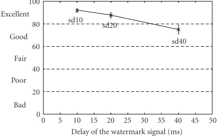
5.1.1. Effect of the delay
The relationship of the quality and the delay is shown in Figure 9. Most subjects could notice acoustic impairments in sd40 and reduced its score to “good” quality. Especially in
the case of castanets (Figure 10), the watermark sound with
a large delay could be heard as additional small castanets. A
similar effect also occurred for drumbeats and cymbals in the
popular music (Figure 11). In those cases, the subjects
per-ceived increased noisiness at the higher frequencies. For the test samples in which long notes were held for some seconds (Figure 12), the effect of the delay was low. In general, the
quality difference between sd10 and sd20 was assessed to be
small, and subjects sometimes gave sd20 better evaluations than sd10.
5.1.2. Effect of the sound source direction
The relationship of the quality and the sound source
di-rection is shown inFigure 13. The effect was so large that
sa30 was assessed in the range of “fair.” When the WS was
played from SP4, the subjects noticed the difference by
per-ceiving a weak stereo effect. However, in the case of sd20,
even though the WS was played from SP2 in addition to the HS from SP1, the subjects perceived the mixed sound as a
monaural sound. The effect was particularly prominent for
sa30 sd40 sd10 am48 hr
r am64 al7 sd20 sa15
0
Figure8: The mean and 95% confidence interval of the subjective acoustic quality of the test signals for all subjects. The test signals are described inTable 2.
50
Delay of the watermark signal (ms) 0
Figure 9: The relationship between the delay of the WS and the
subjective acoustic quality.
Figure10: The subjective acoustic quality of the instrumental solo test sample is1, “castanets.”
the test samples for which the effect of the delay was
dis-tinguishable. Although the situation would be more compli-cated with multiple sources of the host sound for the realistic use of sonic watermarking, the experimental results suggest the sound source of the WS should be placed as close to the source of the host sound as possible.
6. ROBUSTNESS
sa30
Figure11: The subjective acoustic quality of the popular music test sample ip3, “Mai Kuraki.”
sa30
Figure12: The subjective acoustic quality of the orchestral music test sample io2, “wind ensemble.”
35
Angle between the sound sources (degree) 0
Figure13: The relationship between the offset angle of the sound sources and the subjective acoustic quality.
watermarking: sonic propagation, echo addition, noise addi-tion, and MP3 compression. The results of the tests were col-lected for three categories: (a) popular music, (b) orchestral music, and (c) instrumental solos. The numbers of test
sam-ples and the duration for each category are listed inTable 4.
The test samples of instrumental solos included 59 samples
of performance of single instruments from SQAM.5 All of
the signals were monaural and sampled at a frequency of 44.1 kHz and with a bit resolution of 16 bits. Since it has been
shown in [8] that real-time sonic watermarking using the
proposed algorithm is feasible, we did not use real-time
wa-termarking for the tests. We calculated the WS off-line, and
added them to or played them simultaneously with the HS.
5Sound quality assessment material disc produced by the European Broadcasting Union for subjective tests.
Table4: The number and the durations of the test samples used for the robustness tests.
Category Number of samples Duration
Popular Music 20 92 min
Orchestral Music 13 112 min
Instrumental Solos 76 120 min
Table5: The CDRs at which the correct 64-bit messages were de-tected. Watermark embedding was performed by digital addition (Digital WM) or sonic watermarking (sonic WM). Detection was done immediately after embedding or after MP3 compression and decompression.
Popular Music Digital WM Sonic WM
Original watermark 100% 96%
MP3 64 kbps 100% 96%
MP3 48 kbps 100% 95%
Orchestral Music Digital WM Sonic WM
Original watermark 100% 99%
MP3 64 kbps 100% 99%
MP3 48 kbps 100% 97%
Instrumental Solos Digital WM Sonic WM
Original watermark 99% 60%
MP3 64 kbps 97% 53%
MP3 48 kbps 66% 37%
6.1. Results
We measured the correct detection rates (CDRs) at which the correct 64-bit messages were detected. The error correction and detection algorithm successfully avoided the detection of an incorrect message.
6.1.1. Robustness against MP3 compression
Table 5 shows the results for sonic watermarking and MP3 compression. “Digital WM” means that the WS was digitally added to the HS with a delay of 20 milliseconds. “Sonic WM” means that the sound of the WS was mixed with the host sound in the air and recorded by a microphone. We used the same experimental equipment as used for sd20 of the listening test. For the “original watermark,” the watermark was detected immediately after watermark embedding as de-scribed above. For “MP3,” the watermarked signal was com-pressed in an MP3 file with the specified bit rate for a monau-ral channel and then decompressed before watermark detec-tion. For popular music and orchestral music, correct water-marks were detected from over 95% of detection windows after sonic watermarking and MP3 compression. The rea-son the CDRs for instrumental solos were low is that the test samples included many sections that are almost silent or at a quite low volume, and the watermarks in those sections were easily destroyed by the background noise of the room and by
the MP3 compression. We observed a 28 dB(A)6background
noise in the soundproof room when nothing was played by the speakers.
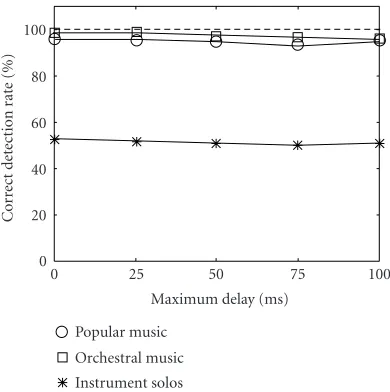
100
Figure14: The CDRs after sonic watermaking and echo addition.
The leftmost points are the rates immediately after sonic watermak-ing.
6.1.2. Robustness against echo addition
Figure 14shows the CDRs after sonic WM and echo addi-tion. Echoing was done digitally on a computer with a
feed-back coefficient of 0.5. The horizontal axis of the figure is the
value of the maximum delay used for echo addition. Though the CDRs for the instrumental solos were low because of sonic WM, it can be seen that echo addition interferes very little with watermark detection.
6.1.3. Robustness against noise addition
Figure 15shows the CDRs after sonic WM and noise addi-tion. White Gaussian noises with an average noise-to-signal ratio shown in the horizontal axis of the figure were digi-tally added to the recordings. For popular music, the CDRs
remained high up to−20 dB of noise addition. In contrast,
the CDRs for orchestral music dropped after noise addition
above−35 dB. This is because orchestral music has wider
dy-namic ranges than popular music does, and contains more low volume sections. Those quiet sections degrade more quickly than loud sections do when the additive noise has
a comparable signal level. Though it has been shown in [8]
that CDR for quiet sections can be improved, at the sacrifice
of transparency, by utilizing the masking effect of the
back-ground noise, the robustness against noise when the masking
effect is not used by the watermark generator is still an open
problem.
7. SUMMARY
In this paper, we introduced the idea of sonic watermark-ing that mixes the sound of the watermark signal and the host sound in the air to detect bootleg recordings. The pos-sible problems that may limit the use of sonic watermarking were classified. We proposed an audio watermarking algo-rithm suitable for sonic watermarking. The subjective
acous-−20 −25 −30 −35 −40
Additional noise level (dB) 0
Figure15: The CDRs after sonic watermaking and noise addition. The leftmost points are the rates immediately after sonic watermak-ing.
tic quality of the algorithm was assessed in the range of “ex-cellent” quality by the MUSHRA listening test. We assessed
the effect of the delay of the watermark signal on the quality,
and found that 20 milliseconds were short enough to
sus-tain excellent quality. The effect of the direction of the sound
sources of the watermark signal and the host signal was so large that special attention should be paid to the placement of the sound sources when using sonic watermarking. The experimental results of robustness were dependent on the type of the music samples. For popular music, the watermark was quite robust so that correct messages were detected from over 90% of the detection windows even when noise addi-tion, echo addiaddi-tion, or MP3 compression was performed af-ter sonic waaf-termarking. However, in the case of instrument solos, since the watermarks for low volume sections were eas-ily degraded by the background noise, the CDR after sonic watermarking was only 60%.
Because this is the first attempt of this kind, there are still large problems to solve with sonic watermarking. The robustness of low volume sections and the acoustic trans-parency certainly have a room to improve. Some other au-dio watermarking algorithms might be also suitable for sonic watermarking. We need to theoretically and experimentally
compare those algorithms. To evaluate the effects of the
REFERENCES
[1] W. Bender, D. Gruhl, N. Morimoto, and A. Lu, “Techniques for data hiding,”IBM Systems J., vol. 35, no. 3-4, pp. 313–336, 1996.
[2] D. Gruhl, A. Lu, and W. Bender, “Echo hiding,” inInformation Hiding Workshop, pp. 293–315, Cambridge, UK, 1996. [3] L. Boney, A. H. Tewfik, and K. N. Hamdy, “Digital watermarks
for audio signals,” inProc. IEEE International Conference on Multimedia Computing and Systems, pp. 473–480, Hiroshima, Japan, June 1996.
[4] M. D. Swanson, B. Zhu, A. H. Tewfik, and L. Boney, “Robust audio watermarking using perceptual masking,” Signal Pro-cessing, vol. 66, no. 3, pp. 337–355, 1998.
[5] J. Haitsma, M. van der Veen, T. Kalker, and F. Bruekers, “Audio watermarking for monitoring and copy protection,” inProc. ACM Multimedia 2000 Workshops, pp. 119–122, Los Angeles, Calif, USA, November 2000.
[6] R. Tachibana, S. Shimizu, S. Kobayashi, and T. Nakamura, “Audio watermarking method robust against time- and frequency-fluctuation,” inSecurity and Watermarking of Mul-timedia Contents III, vol. 4314 ofProceedings of SPIE, pp. 104– 115, San Jose, Calif, USA, January 2001.
[7] D. Kirovski and H. Malvar, “Spread-spectrum audio wa-termarking: requirements, applications, and limitations,” in IEEE 4th Workshop on Multimedia Signal Processing, pp. 219– 224, Cannes, France, October 2001.
[8] R. Tachibana, “Audio watermarking for live performance,” inSecurity and Watermarking of Multimedia Contents V, vol. 5020 of Proceedings of SPIE, pp. 32–43, Santa Clara, Calif, USA, January 2003.
[9] D. Delannay, J.-F. Delaigle, B. M. Macq, and M. Barlaud, “Compensation of geometrical deformations for watermark extraction in digital cinema application,” inSecurity and Wa-termarking of Multimedia Contents III, vol. 4314 ofProceedings of SPIE, pp. 149–157, San Jose, Calif, USA, January 2001. [10] A. van Leest, J. Haitsma, and T. Kalker, “On digital cinema
and watermarking,” inSecurity and Watermarking of Multi-media Contents V, vol. 5020 ofProceedings of SPIE, pp. 526– 535, Santa Clara, Calif, USA, January 2003.
[11] ITU-R, Method for the Subjective Assessment of Intermediate Quality Level of Coding Systems, Recommendation BS.1534-1,http://www.itu.int/search/index.html.
[12] E. Zwicker and H. Fastl, Psychoacoustics, Springer-Verlag, New York, NY, USA, 2nd edition, 1999.
[13] ISO/IEC, “Coding of moving pictures and associated audio for digital storage media at up to about 1.5 Mbit/s – part 3: Audio,” Tech. Rep. 11172-3, 1993.
[14] C. Neubauer, R. Kulessa, and J. Herre, “A compatible family of bitstream watermarking schemes for MPEG-audio,” inProc. 110th Convention Audio Engineering Society, Amsterdam, The Netherlands, May 2001.
[15] R. Tachibana, S. Shimizu, S. Kobayashi, and T. Nakamura, “An audio watermarking method using a two-dimensional pseudo-random array,” Signal Processing, vol. 82, no. 10, pp. 1455–1469, October 2002.
[16] S. Shimizu, “Performance analysis of information hiding,” inSecurity and Watermarking of Multimedia Contents IV, vol. 4675 ofProceedings of SPIE, pp. 421–432, San Jose, Calif, USA, January 2002.
[17] M. J. Crocker, “Rating measures, descriptors, criteria, and procedures for determining human response to noise,” in En-cyclopedia of Acoustics, M. J. Crocker, Ed., vol. 2, chapter 80, pp. 943–965, John Wiley & Sons, New York, NY, USA, 1997.
Ryuki Tachibanais a Researcher at Tokyo Research Laboratory of IBM Japan. He re-ceived his Master’s degree in aerospace en-gineering from the University of Tokyo, Japan, in 1998, where he studied application of artificial intelligence, computer-aided de-sign, and cognitive science to aerospace en-gineering. Since he joined IBM Japan in 1998, his main research interests have been in the field of digital watermarking. He has