R E S E A R C H
Open Access
An improved three-coil wireless power link
to increase spacing distance and power for
magnetic resonant coupling system
Xian Zhang
1*, Hao Meng
1, Bin Wei
2, Songcen Wang
2and Qingxin Yang
1Abstract
When wireless power transfer (WPT) technology is used to power the sensor networks, it is necessary to increase the transmission power and distance. We strictly deduced two necessary conditions for strong coupling by coupled mode theory. Next, the transmission power and efficiency as a function of coupling coefficient and quality factor are derived, and the maximum active power of the load depends on the coupling coefficient between resonators, quality factor of the resonator and the drive power. In order to increase transmission power and distance, an improved three-coil wireless power link is proposed. Meanwhile, an experimental platform was established, and the experimental results show that the transmission power can reach 120 W at a distance of 2.5 m. This proves that the improved three-coil wireless power link is very effective.
Keywords:Three-coil wireless power link, Magnetic resonant coupling, Coupled mode theory, Critical strong coupling, Optimal impedance feed
1 Introduction
The magnetic resonant coupling wireless power transfer (MRC-WPT) was first proposed by MIT’s team in 2007 [1] and is now gaining more spotlights ranging from contactless battery charging of consumer electronics [2], electric vehicles [3–5], to biological implanted devices’ power supply [6,7].
WPT technology can be categorized according to their operating frequencies, which are short-range inductive power transmission (IPT) (at the range of a few hundred kilohertz), mid-range MRC-WPT also known as WiTricity (at the range of several MHz) and long-range directly microwave radiation (range above GHz) [8, 9]. Different from other two methods, MRC-WPT operates in strong coupling state to transfer energy wirelessly via evanescent non-radiative near field. High-frequency power flows among resonators in a mid-range which is on the order of several times the physical size of transmitting or receiving end when system is tuned into resonant state and finally
absorbed by the load. Moreover, it interacts weakly with biological tissues or other non-resonant objects.
In the past two decades, IPT is the mainstream of WPT and its transmission distance is short. However, MRC-WPT has a significant increase in transmission distance. For mid-range applications, MRC-WPT is a good choice to reach a range of meters, which is of great significance for the power supply of wireless sensor net-works [10, 11]. Nevertheless, the transmission power of MRC-WPT system decreases with increasing transmis-sion distance because the magnetic coupling is relatively small at longer distances. Therefore, power transmission range needs to be extended to achieve more flexibility.
Several methods were previously proposed to accom-modate power pickups when there is deviation in radial direction. In [12], a multiphase system is proposed to obtain a wider power delivery zone. In [13], a wide power transmission area is achieved by two transmit-ters. In [14], a cooperative operating coupler featuring tight-strong coupling is proposed to enhance anti-offset capability. However, transmission distance cannot be extended in coil axis directions by these methods.
In [15–17], superconductor is utilized to reduce the coil losses and increase transmission distance. But it is
* Correspondence:[email protected]
1Tianjin Key Laboratory of Advanced Electrical Engineering and Energy
Technology, Tianjin Polytechnic University, Tianjin 300387, China Full list of author information is available at the end of the article
and power at a reasonable level of efficiency. First, the time domain solution of power exchange between two resonators is achieved through coupled mode theory. Two key prerequisites of strong coupling are deduced by discussing the angular frequency, mode coupling factor and quality factor. After that, the overall transmission efficiency and the maximum power of the load are ana-lysed. Finally, a three-coil wireless power link containing two helix resonators and a device coil was established, and power on the load reached 120 W with transmission distance up to 2.5 m. Measured values have an error of ± 2.5% compared to theoretical ones.
2 Methods/experimental section
It is necessary to increase the load power and to extend the transmission distance in axial direction for MRC-WPT system. Though there is high power over kilowatts and long distance over several kilometres via micro-wave transmis-sion, it is far from safety and stability compared to MRC-WPT by using the non-radiative near field. When the electrical parameters are fixed, the maximum active power the load can get depends on the coupling coefficient between resonators, quality factor of the resonator and the drive power. Therefore, if we intend to increase the load power, the overall contribution of three parameters above should be concerned.
It can be seen from the calculation formula (Q=ωL/R) of the resonator quality factor that the quality factor can be improved in two aspects: (1) increasing the ratio of inductance and resistance and (2) increasing the natural resonant frequency. In this paper, in order to increase the quality factor of the resonators, the oxygen-free copper tube with smooth surface is relatively nice material, be-cause it has good conductive property and skin effect is reduced to some extent. It should be noted that there is only limited improvement for the ratio of inductance and resistance. The efficient way to get a larger quality factor is to increase the natural resonant frequency. With partici-pation of the distributed capacitance between coil tubes, the resonant frequency is up to 13.56 MHz with the qual-ity factor of 1100~1500.
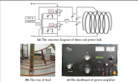
In our project, high-frequency power is fed directly to the transmitting resonator. The high-frequency signal is
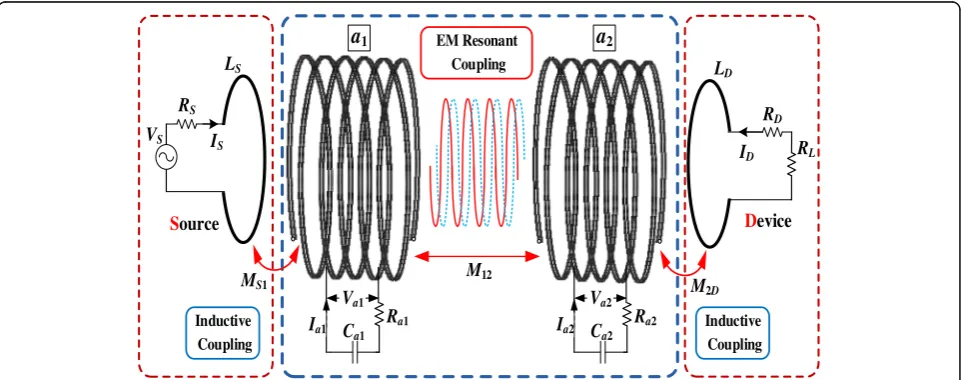
A general configuration of MRC-WPT system is shown in Fig. 2; there are three sections to fulfil the functions of power coupling, transformation and transmission. Power on resonator a1,2 is acquired through inductive coupling to achieve the conversion of low voltage/high current and high voltage/low current between resonators and source or device coil. Once the system is tuned into resonant state, power exchanges between the resonators through EM resonantly coupling which results in a rela-tively low transmission loss by high impedance perform-ance.Va1,2,Ia1,2,Ca1,2andRa1,2are equivalent to voltage, current, capacitance and resistance of resonator a1,2, respectively; I1,2, RS,D and LS,D are current, resistance and induction of source coil and device coil; VS is driving voltage;RLis load resistance;MS1, M1,2 andM2D are mutual induction between the coils. Here, the coup-ling effect between non-resonant source and device coil is ignored.
3.1 Prerequisites for efficient wireless power transfer
The coupled mode theory is usually employed to de-scribe the general laws of wave interaction phenomena such as optical waves and sound waves. It is very suit-able for modelling the resonant energy exchange. For the lossless resonators in a MRC-WPT system, energy exchange between resonators can be described by two decoupled differential equations as (1) [19].
da1
initial condition as Γ{t= 0, a1(t) =A(t); a1(t) = 0}, the solution can be derived as (2), where ω is the average value ofω1andω2.
a1ð Þ ¼t Að Þ0 cosð Þ þΩt jω1−ω2
2Ω sinð ÞΩt
h i
ejωt a2ð Þ ¼t Að Þ0 κ21 sinð Þ=Ωt Ωejωt
(
ð2Þ
Their two eigenvalues are λ12= ±Ω= [(ω1−ω2)2/4
−κ12*κ21]0.5. There is the first prerequisite that the max-imum energy exchange exists unlessω1=ω2. It is simple and intuitive but explains why the two circuits have to be tuned into resonance.
For a lossy coupling system, the natural resonant angular frequency will have an offset, and modified resonant angular frequency can be expressed as ω’ 1,2 =ω1,2 (1 +j/2Q1,2). The eigenvalues can be expressed as (3) by Taylor expansion, when the quality factor Q is high enough. In general, for more convenient impedance matching, the resonators are designed to be the same size, resonant frequency and quality factor, so there are Q1=Q2=Qandω1=ω2=ω.
λ1;2¼− ω
Q
ffiffiffiffiffiffiffiffiffiffiffiffiffi κ12κ21
p ð
3Þ
If we intend to obtain a sustaining growth in oscillation, it must meet the condition that there is a positive root and the item within the radical sign is a real number. In general, the parameters of resonators are designed to be the same, so there areQ1=Q2=Qandω1=ω2=ω. And the second prerequisite is shown as (4) after simplification.
κ12κ21
j j>> ω2
4Q2 ð4Þ
The two mode coupling factors denote the energy coupling rate; the two quality factors denote the loss rate. In other words, the resonators with high-quality factors are needed to form a low-loss bridge for energy flowing between the source and device.
Energy exchange relationship between resonators in normalization is shown as Fig. 3 in which |a1|2, |a2|2 and |a1+a2|2 indicate energy of resonator 1, 2 and overall system. Presence of quality factor Q makes the overall energy decays exponentially. Reason of attenu-ation in linear system includes Joule loss and radiattenu-ation
(a)
The structure diagram of three-coil power link
(b)
The way of feed
(c)
The dashboard of power amplifier
loss which can be expressed as absorption and radi-ation of Q value. As shown in Fig. 3a with ω1=ω2 and different mode coupling factor, though there is almost 100% energy exchange, it cannot keep sustain-ing and attenuatsustain-ing through several cycles. Usually, the distance between the two resonators is several times of them. So it can be called as loose coupling mode. In Fig. 3b, when angular frequencies differ greatly, most of energy were stored in resonator 1, and the receiver gets very limited energy which is the main reason of decline in transmission power and overall efficiency, which can be called as weak coupling mode. As soon as the two requirements are met, it is working under the strong coupling state in which proportion of energy exchange reaches 100% theoretically, as shown in Fig. 3c, which can be called as strong and tight coupling mode.
Quality factor reflects the ratio of EM energy stored in circuit and energy consumed in a cycle when in reson-ance. Energy consumption comes from the resonator itself and load resistance. For high-Q resonator, RD is small enough to be ignored, and the value of equivalent quality factorQ′is more close toQL. Therefore, active power on the loadPLis
PL¼A 2
ω0 4k212
QL
k212þ1=ðQQLÞ
−2
ð6Þ
So when resonance occurs,PLis a multivariate func-tion of excitafunc-tion power, resonant angular frequency, coupling coefficient and quality factor. Figure 4 shows the variation of normalized PL with load quality factor and coupling coefficient, wherein logarithmic coordi-nates are used to facilitate observation except z-axis. When operating frequency is kept constant, PL is not always increasing withk12, but reaches maximum under a certain condition which is the critical coupling position. In general, coupling coefficient changes with the spacing variation, and other parameters are fixed
Ra1
VS RS
RL RD
I1 I2
Ca1
Va1
Ia1
Source Device
a
1a
2Ra2
Ca2
Va2
Ia2
LS LD
MS1 M12 M2D
EM Resonant Coupling
Inductive Coupling Inductive
Coupling
IS I
D
Fig. 2Directly field-circuit model of a MRC-WPT system. The analysis of the coupling principle of the field-circuit is shown in Fig.2. The source coil and device coil are coupled with the resonant coils through inductive coupling, and the resonant coils perform power transmission through EM resonant coupling
Ω
Resonant frequency(MHz) 10.1–14.5 –
values. Thus, the maximum active power obtained by the load is
PLmax¼A 2
ω0Q ð
7Þ
To derive the transmission efficiency function, we as-sumed that external objects do not participate in energy exchange. Active power consumption result in the loss on load power, a1 and a2. While power consumption can be divided into Joule losses and radiation losses of a certain dose, both can be embodied by equivalent quality factor. So the overall efficiencyηcan be expressed as:
η¼ PL
Ptotal
¼ ðQ=QLÞ ðk12QÞ2 1þQ=QL
ð Þ2þ
1þQ=QL
ð Þ ðk12QÞ2
ð8Þ
And the maximum transmission efficiency can be obtained from (8) as:
ηmax¼1−2=ð1þQ=QLÞ ð9Þ
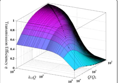
It can be drawn that linear resonant coupling system transmission efficiency depends mainly on two factors. The first item Q/QL shows the role of impedance matching circuit. Here, the load quality factor is generally less than the oscillator quality factor which ensures that transmission efficiency is always over zero. When QL<<Q, system efficiency approaches the maximum which indicates power is all absorbed by the load. When QL=Q, efficiency is almost zero, indicating that power stored around the load
(a)
loose coupling mode(b)
weak coupling mode(c)
strong and tight coupling modeFig. 3Schematic of normalized energy exchanging. Normalized energy exchanging is solved by coupled mode method. In loose coupling mode, the power of the system quickly attenuates to zero. In weak coupling mode, the rate of energy exchange between the transmitter and the receiving end is very small; it means that the transmitting efficiency is low. In strong and tight coupling mode, the system will work in a highly efficient transmission and low-loss state.aLoose coupling mode.bWeak coupling mode.cStrong and tight coupling mode
Fig. 4Normalized active powerPLas a function ofk12andQL. LEGEND:
The abscissa axis is the coupling coefficientk12and the load quality factorQL. They are two important parameters affecting the power. The
composed of four coils which are source coil, two resona-tors and device coil, as shown in Fig.2. In section III, the energy exchange between two resonators is mainly ana-lysed by the coupled mode theory. There is also energy transmission between source coil or device coil and reso-nators. In the resonant state, the transmission efficiencies between two adjacent coils can be expressed by circuit theory as: can be seen that when the quality factor of coils andk12 are constant, the increase of coupling coefficientskS1and k2Dcontribute to the improvement of the efficiency. How-ever, the source coil and the device coil have the function
k
tors, it determines the state of system. Once the coupling coefficientk12exceeds the threshold value, frequency split-ting disappears andPLdecreases with the reduction ofk12. In general, MRC-WPT system is intended to operate in a far enough distance to increase the flexibility of power supply. Therefore, the remaining method to reduce damp-ing effect is to choose the coils with larger dimension and more number of turns. However, for helical resonator, this is also a way to reduce the flexibility of MRC-WPT.
Only the characteristic impedance of the coil matches the output impedance of the power supply; there will be no reflected power. The degree of matching is com-monly measured by the reflectance coefficient, as shown in (11).
Γ¼ Zo−R0S
ZoþR0S ð
11Þ
where Zo is the characteristic impedance of the reson-ator. In order to achieve this purpose, the resonators adopt γ matching method whose feed position is in the centre of the coil, and its characteristic impedance can be adjusted until it matches the output impedance of the
Fig. 5Transmission efficiencyηas a function ofQ/QLandk12Q. The
abscissa axis isQ/QLandk12Q. For system efficiency, it is related to
many factors. In this paper, we combine the relevant factors to see the relationship of efficiency more directly
Fig. 6Transmission efficiencyηand power of the loadPLas a
function of spacing distance. Transmission efficiencyηand power of the loadPLas a function of spacing distance is shown in this
figure. The transmission efficiencyηcurves of theoretical value and experimental value when the frequency can be varied decay with the increase of distance. When the frequency is constant, there is a peak value of the loadPL. The curve shows that the error between
power supply. The output impedance of the power supply is generally 50Ω. Meanwhile, the resonator of reception side uses the same method to adjust impedance. In this way, the maximum source power is loaded to resonator and efficiently transmitted to the load.
In order to verify the transmission performance of the improved three-coil link, a three-coil wireless power transfer system was established and its transmission performance was tested within the distance of 0 to 3 m. Theoretical and experimental values of η and PL as a function of spacing distance is shown in Fig. 6. Two 60-W bulbs connected in parallel are the load whose power has experienced a process of first increasing and then decreasing. And the power reaches a maximum of 120 W at a distance of 1.5 m. It is the critical coupling point when frequency keeps constant. The efficiency curve shows that the closer two resonators, the higher the efficiency is when frequency can be varied. However, it will decrease when distance is greater than 1.5 m. When source power is increased to 300 W, it can still supply 120 W at 2.5 m under efficiency about 32% from DC power to the load, as shown in Fig.7.
5 Conclusions
Precondition of energy exchange in strong coupling can be expressed as follows: the angular frequency of resona-tors is equal, and the product of coupling coefficient and quality factor is much larger than 1. We further derived that efficiency was constrained byQ/QLand k12Qwhich reflect the contribution by electrical structure and spacing distance respectively. The maximum active power of the load depends on the coupling coefficient between resonators, quality factor of the resonator and the drive power. An improved three-coil wireless power link is proposed to maximize the transmission distance
and power at a reasonable level of efficiency. Meanwhile, a centre feed method is applied to resonators to achieve good impedance matching. In order to verify the theory, two 220 V/60 W bulbs are used as load, and MRC-WPT system with helical centre feed coils are designed. Exper-iments show that 120 W can be wirelessly transmitted at a distance of 2.5 m which is two times the power, 1.25 times the distance and 2.13 times the efficiency of [1]. In the future work, we can use this system to supply power for wireless sensor networks.
Abbreviation
MRC-WPT:Magnetic resonant coupling wireless power transfer; WPT: Wireless power transfer
Acknowledgements
This work was supported by the Science and Technology Project of State Grid Corporation of China: Research on Electromagnetic Safety Evaluation and Test method of Wireless Charging for Electric Vehicles.
Authors’contributions
XZ is the main writer of this paper. He proposed the main idea, deduced the performance of WPT detection, completed the simulation and analysed the result. HM introduced the algebraic equation of power and efficiency by coupled mode theory. BW and SW provided experimental environment and completed the experiment. QY gave some important suggestions for three-coil wireless power link. All authors read and approved the final manuscript.
Authors’information
Zhang Xian, male, Ph.D., Associate professor of Tianjin Key Laboratory of Advanced Electrical Engineering and Energy Technology come from Tianjin Polytechnic University (TJPU), Tianjin, China, was born in Hebei, China, on Dec 1983. He received the Bachelor degree from Hebei University of Technology (HEBUT) in 2009, majoring in Electrical Engineering, and the Doctor Degree in Engineering form HEBUT in 2012. Now, he majors in wireless power transmission and standards in TJPU.
Meng Hao was born in Hebei Province, People’s Republic of China, in Apr 1990. He received B.S. degree from Hebei University in 2016, majoring in Electrical Engineering. He is currently working toward the M.S. degree in School of Electrical Engineering and Automation, Tianjin Polytechnic University. His research interest is wireless power transfer.
Wei Bin, male, Ph.D., Professor of engineering, come from China Electric Power Research Institute (CEPRI), Beijing, China, was born in Hubei, China, on 2.5m
0.2m
0.6m
received the Bachelor degree from Hebei University of Technology (HEBUT) in 1986, majoring in Electrical Engineering, and the Doctor Degree in Engineering form HEBUT in 1997. Now, he majors in Engineering electromagnetic field and magnetic technology in TJPU.
Competing interests
The authors declare that they have no competing interests.
Publisher’s Note
Springer Nature remains neutral with regard to jurisdictional claims in published maps and institutional affiliations.
Author details 1
Tianjin Key Laboratory of Advanced Electrical Engineering and Energy Technology, Tianjin Polytechnic University, Tianjin 300387, China.2China
Electric Power Research Institute, Beijing 100085, China.
Received: 14 February 2018 Accepted: 10 May 2018
References
1. A Kurs, A Karalis, R Moffatt, et al., Wireless power transfer via strongly coupled magnetic resonances. Science317(5834), 83–86 (2007) 2. VT Nguyen, SH Kang, JH Choi, et al., Magnetic resonance wireless power
transfer using three-coil system with single planar receiver for laptop applications. IEEE Trans. Consum. Electron.61(2), 160–166 (2015) 3. X Zhang, Z Yuan, Q Yang, et al., Coil design and efficiency analysis for
dynamic wireless charging system for electric vehicles. IEEE Trans. Magn.52(7), 1–4 (2016)
4. SC Moon, GW Moon, Wireless power transfer system with an asymmetric four-coil resonator for electric vehicle battery chargers. IEEE Trans. Power Electron.31(10), 6844–6854 (2016)
5. X Zhang, P Zhang, Q Yang, et al., Magnetic shielding design and analysis for wireless charging coupler of electric vehicles based on finite element method. Transactions of China Electrotechnical Society31(1), 71–79 (2016) 6. YY Ko, SL Ho, WN Fu, et al., A novel hybrid resonator for wireless
power delivery in bio-implantable devices. IEEE Trans. Magn.48(11), 4518–4521 (2012)
7. D Ahn, M Ghovanloo, Optimal design of wireless power transmission links for millimeter-sized biomedical implants. IEEE Transactions on Biomedical Circuits and Systems10(1), 125–137 (2016)
8. Q Yang, P Zhang, L Zhu, et al., Key fundamental problems and technical bottlenecks of the wireless power transmission technology. Transactions of China Electrotechnical Society30(5), 1–8 (2015)
9. X Zhang, Z Yuan, P Zhang, et al., Transmitting capacity estimation and verification for wireless power transmission system via electromagnetic resonant coupling. Transactions of China Electrotechnical Society30(19), 47–54 (2015)
10. Y Dong, L Yu, L Li, et al., Resonance wireless power transmission technology theory and its applications in the micro-sensor. Microcomputer & Its Applications33(3), 1–4 (2014)
11. B Kallel, O Kanoun, H Trabelsi, Large air gap misalignment tolerable multi-coil inductive power transfer for wireless sensors. IET Power Electron.9(8), 1768–1774 (2016)
12. GA Covic, JT Boys, M Kissin, et al., A three-phase inductive power transfer system for roadway-powered vehicles. IEEE Trans. Ind. Electron. 54(6), 3370–3378 (2007)
18. AP Sample, DA Meyer, JR Smith, Analysis, experimental results, and range adaptation of magnetically coupled resonators for wireless power transfer. IEEE Trans. Ind. Electron.58(2), 544–554 (2011)