for MPEG-4 Talking Heads
Nikos Grammalidis
Informatics and Telematics Institute, Centre for Research and Technology Hellas, 1st Km Thermi-Panorama Road, Thessaloniki 57001, Greece
Email: [email protected]
Nikos Sarris
Information Processing Laboratory, Electrical and Computer Engineering Department, Aristotle University of Thessaloniki, Thessaloniki 54006, Greece
Email: [email protected]
Fani Deligianni
Informatics and Telematics Institute, Centre for Research and Technology Hellas, 1st Km Thermi-Panorama Road, Thessaloniki 57001, Greece
Email: [email protected]
Michael G. Strintzis
Informatics and Telematics Institute, Centre for Research and Technology Hellas, 1st Km Thermi-Panorama Road, Thessaloniki 57001, Greece
Email: [email protected]
Received 31 August 2001 and in revised form 14 May 2002
This paper studies a new method for three-dimensional (3D) facial model adaptation and its integration into a text-to-speech (TTS) system. The 3D facial adaptation requires a set of two orthogonal views of the user’s face with a number of feature points located on both views. Based on the correspondences of the feature points’ positions, a generic face model is deformed nonrigidly treating every facial part as a separate entity. A cylindrical texture map is then built from the two image views. The generated head models are compared to corresponding models obtained by the commonly used adaptation method that utilizes 3D radial bases functions. The generated 3D models are integrated into a talking head system, which consists of two distinct parts: a multilingual text-to-speech sub-system and an MPEG-4 compliant facial animation sub-system. Support for the Greek language has been added, while preserving lip and speech synchronization.
Keywords and phrases:MPEG-4, 3D model-based coding, text-to-speech, facial adaptation, talking face.
1. INTRODUCTION
Talking heads apply in a great variety of applications, such as human-machine interfaces (HMI) or virtual reality applica-tions. For example, such systems can be used in information kiosks, virtual shopping agents, news and e-mail reading in the Internet, for pleasant navigation tours in 3D worlds or for interactive educational software. Although cartoon-like characters can be used in some of these applications, synthe-sizing photo-realistic models of a specific person, although challenging, opens new horizons in realism and personaliza-tion.
The system presented here can be used to generate per-sonalized 3D talking heads based on a generic MPEG-4
compliant model by using a new 3D adaptation approach. Our system consists of three modules: the 3D facial adap-tation algorithm, the text-to-speech converter and the facial animation engine. These will be outlined separately in the following paragraphs and in detail in the following sections.
to facial features. In [3, 4], the deformation is performed by an interpolation scheme utilizing radial basis functions. In [5], two orthogonal photos of the target face are used and the generic face model is deformed by a 3D geometric trans-formation, specifically the Dirichlet free form deformation (FFD) [6, 7]. In [8], the required 3D positions of the facial features are estimated from a series of captured image frames of the target face and the generic model is transformed by ap-plying an interpolation function based on radial basis func-tions. Information from one view of the target face is uti-lized in [9] to measure the face, eyes, and mouth dimensions which are used to adapt a simple 3D face model by rigidly transforming the whole face and locally correcting the posi-tion and orientaposi-tion of the face, eyes, and mouth. Geometric assumptions have to be made however, as the 3D character-istics of the features cannot be totally deduced from only one view.
Our approach differs from those of all above methods in that it treats the facial model as a collection of facial parts, which are allowed to deform according to separate affine transformations. This is a simple method which does not require the use of any specialized equipment (as a 3D laser scanner) and is effective for face characterization because the physiological differences in characteristics between faces are based on precisely such local variations, that is, a person may have a longer or shorter nose, narrower eyes, and so forth. Thus, in the proposed method after rigidly transforming the whole model so that it is aligned and scaled according to the target face, each facial part is stretched, rotated, and trans-lated separately and in the optimal way (by minimization of a distance cost function) to fit to the required corresponding target facial part. The model nodes between different parts are interpolated to provide a natural smooth transition from one facial part to the other.
The available front and profile views of the face are then combined using the knowledge of the human face symmetry to generate a texture map containing the texture information for the entire head. The texture value stored to the texture map is produced as an average of the corresponding color values obtained by projecting the corresponding 3D point to the available images.
The generated 3D models are then integrated into a talk-ing head system which consists of two distinct parts: a multi-lingual text-to-speechsystem and a facial animationengine based on MPEG-4 facial animation parameters (FAPs).
A text-to-speech synthesizer is a computer-based system that should be able to read any text aloud [10]. A talk-ing head combines the TTS engine with a facial anima-tion engine able to naturally reproduce a person’s facial ex-pressions while he is reading a specific text. While various commercial [11, 12] and research [13, 14] talking head sys-tems are already available, the MPEG-4 standard provides new kinds of standardization to the field. The synthetic-natural hybrid coding (SNHC) part of MPEG-4 describes all possible facial movements and expressions using 68 pa-rameters, referred as facial animation parameters (FAPs). Al-though MPEG-4 supports TTS synthesis by providing an in-terface to a proprietary text-to-speech synthesizer (TTSI),
the synchronization of the FAP synthesizer with the TTS sys-tem, which is usually an asynchronous source, is generally difficult [15]. As in [15], we have solved the problem by con-verting the phonemes (and facial expressions that input by the user as special characters—smileys along with their dura-tion) to FAPs. Since the durations of the phonemes are avail-able both the TTS and the facial animation engine, lip and speech synchronization is always achieved.
Many research or commercial TTS synthesizers are cur-rently available. We have chosen to base our system to the multilingual speech synthesizer of the MBROLA project [16]. This synthesizer needs as input a list of phonemes, together with prosodic information (duration of phonemes and a piecewise linear description of pitch), and produces speech samples on 16 bits (linear), at the sampling frequency of the diphone database used. Phoneme transcription is achieved by a rule-based system for the Greek language or by a decision-tree-based system that is trained using a pronun-ciation dictionary for the English language. Durations and prosody information are synthetically generated using tech-niques similar to those developed for the MBRDICO project [17].
The paper is organized as follows: in Section 2, the face model adaptation method is described, while in Section 3 the two parts of the talking head system are presented. Gen-erated 3D models are presented in Section 4 and compared to the same models obtained using the radial basis func-tion (RBF) interpolafunc-tion approach. Finally, conclusions are drawn in Section 5.
2. 3D FACIAL MODEL ADAPTATION
In this section, we propose a method for the adaptation of a generic 3D face model to a face captured from two orthogo-nal views: a front and a profile. A number of feature points have to be located on both (2D) views in order to deduce the 3D positions of the head we wish to model. Several meth-ods exist for the automatic extraction of facial feature points as seen in [18, 19, 20], although no method has yet been re-ported to be 100% accurate and insensitive to lighting and background conditions. Thus, in the presented system, pre-vious work, detailed in [21], has been exploited to locate au-tomatically the positions of the facial features but a manual user interactive tool has also been developed to allow for cor-rections in the calculated positions. This was necessary be-cause the feature points in the two views need to be exactly positioned, as minor errors will result in unnatural looking 3D models.
The rest of this section outlines the proposed facial adap-tation algorithm, which follows the following steps.
(1) Calculation of the 3D positions of the located feature points in the two views.
Focal length,f
Figure1: Image acquisition layout.
required 3D positions, while the rest of the model nodes are displaced so that the natural characteristics of the human face are preserved.
2.1. Calculation of the 3D positions of the features
Having located the set of characteristic feature points in both views, the calculation of their 3D coordinates is carried out in the following way.
We assume the use of a perspective projection camera system, which is shown in Figure 1. The 3D points with co-ordinates (x, y, z) are projected on two image planes, the front and the profile, with perspective rays passing through the two corresponding projection centersC1andC2, which lie within the physical camera and are at a distance bfrom each other. The focal length f is the distance of the image planes from the corresponding centers of projection, while the point where the optical axis of the camera intersects the image plane is called the principal point. For the frontal im-age plane the principal point coordinates are (XF0, YF0) and
for the profile (XP0, YP0). In our experiments, these were fixed
to the centers of the corresponding projection images. Fi-nally,XFandYFare the projections on the frontal view, while
XPandYPare the projections on the profile view of the per-son’s face.
The projection coordinates for the frontal image can be computed from the similar triangles P1C1P0 and p1C1P0, shown in Figure 1. In the same way, the projection coordi-nates for the profile image may also be determined
XF= f−zx+XF0, XP=f
This system gives for every feature point four equations with three unknown (the 3D position of the feature point
(x, y, z)). This is solved by least squares methods, detailed in
the appendix, to provide the 3D position (x, y, z) of every feature point, given the projections of the feature points on the frontal (XF, YF) and profile view (XP, YP).
2.2. Rigid adaptation
Having calculated the positions of the feature points in 3D, a generic 3D facial model needs to be deformed so that its corresponding feature nodes are displaced as close as possi-ble to these required positions, while preserving the natural smoothness and geometry of the human face.
The first part of the deformation involves a rigid transfor-mation of the model. Thus, the model is rotated and trans-lated to match the pose of the real face. The rotation and translation transformations are calculated by a slight mod-ification of the spatial resectionproblem in photogramme-try [22]. Specifically, the relation between the initial and the transformed model is given by
Then the rotation matrixRwill be given by [22]
Our purpose is the minimization of the following sum of squares by appropriate selection of the 6 unknown parame-ters (3 translation coefficients:Tx,Ty,Tzand 3 rotation
an-whereNis the number of feature points located in the front and profile image frames, (xi, yi, zi) are their required posi-tions in the 3D space calculated as described in Section 2.1 and (xi, yi, zi) are the positions of the model 3D nodes
af-ter the transformation (2). This minimization is accom-plished by use of the nonlinear Levenberg-Marquadt algo-rithm [23, 24, 25]. A number of iterations of the above method are used to determine the values of the Euler angles corresponding to the rotation matrixRand the three com-ponents of the translation vectorT.
2.3. Nonrigid adaptation
The rigid transformation may align the generic model with the required face and scale it to meet the total face dimen-sions. However, the local physiology of the face cannot be altered in this way. Thus, in the second step of the adap-tation process the model is transformed in a nonrigid way aiming to further displace the feature nodes bringing them as close as possible to their exact calculated positions, while the facial parts retain their natural characteristics. To per-form this adaptation, the generic model1(shown in Figure 2) is split into separate face parts (left eye, right eye, mouth, etc.) and a rigid adaptation is performed on every part sep-arately. This means that every 3D face part is rotated, trans-lated, and stretched so as to minimize the distances of the feature points belonging to that face part from their required positions. This is accomplished with the following transfor-mations.
1The generic model used in our experiments was adapted from the model provided by Instituto Superior Tecnico (IST), Universidade Tecnica de Lisboa, Portugal [26].
Figure2: Generic 3D head model.
Centering at the origin
The center of the face part is found as the 3D center of the feature nodes contained and the whole part is translated to-wards the origin so that this center is translated on the origin. The same is done with the set of required feature positions (i.e., their center is found and they are translated towards the origin in the same manner).
Alignment
The face part is rotated around the origin so that three lines connecting three pairs of feature nodes are aligned with the corresponding lines connecting the required fea-ture positions. This is accomplished by minimizing the dif-ferences in the gradients of these lines. For one pair of nodes at (x1, y1, z1) and (x2, y2, z2), with required positions at (x1, y1, z1) and (x2, y2, z2) this would involve finding the 3×3 rotation matrixRwhich would perform the following minimization:
The face part is scaled around the origin with different scale factors for every axis (sx, sy, sz) so that the distances
(a)
(b)
(c)
Figure3: Local adaptation of the nose (a), mouth (b), and right eyebrow (c). The wireframe (both textured and transparent) is drawn at the rigidly deformed position, while the arrows represent the nonrigid deformation and the cubes show the desired position of the feature points.
minimized. Thus, if (xRi, yRi, zRi) are the coordinates of the
feature nodes after the rotation and (xi, yi, zi) their required positions this would involve finding the 3×3 scaling matrix Swhich would minimize the following set of equations:
N
After the stretching transformation the face part is translated back towards its original position by adding the position vector of the face part center calculated and subtracted in step 1.
Results of these steps for three facial parts are shown in Figure 3, where the model is drawn at its rigidly deformed position (xi, yi, zi), the arrows show the final nonrigid
dis-placement vectors (xSi, ySi, zSi) and the cubes represent the desired positions for the feature nodes. It is evident that the desired positions of the feature nodes are achieved af-ter the nonrigid deformation (arithmetic results are given
in Section 5), while the neighboring (to the features) nodes exhibit similar motion vectors, thus accomplishing a smooth deformed surface. Visual results of the complete deformed head are given at the end of this section as well as in Section 5. Between all facial parts one series of nodes is defined as border nodes. These nodes may belong to more than one facial part and thus, their deformed positions are found by linear interpolation of their candidate positions according to every facial part they may belong to. This is done to assure that a smooth transition is achieved from one facial part to the other without neglecting the original surface curvature at those points in the generic model.
Thus, the final deformed model adapts to the particular characteristics implied by the feature points (e.g., bigger nose or smaller eyes) keeping the generic characteristics of a hu-man face (smoothness of the skin and symmetry of the face). Figure 4 shows the results of the rigid and nonrigid adapta-tion procedures, by projecadapta-tion of the rigidly and nonrigidly deformed model on the frontal and profile image views of the target face.
Figure4: Rigid (upper) and nonrigid (lower) adaptation of the face model on the front and profile views.
Front or profile view
L(γ,θ)
Lc
Figure5: Projecting the 3D model triangles on the cylindrical sur-face in order to generate the texture map.
of the head model from any given viewing angle. To achieve this the central axis,Lc, of the cylinder must lie within the model. In our implementation this was accomplished by se-lecting the cylinder axis to be the same as the 3D ellipsoid major axis. The mapping of 3D coordinates (x, y, z) to cylin-drical coordinates (yc, θc) (Figure 5) is given by
tanθc=xz−−zx0
0
, yc=y, (10)
where (x0, y0, z0) is the 3D head model centroid. For each position on the cylindrical surfaceC(yc, θc), the
correspond-ing position on a wireframe triangle is found as the intersec-tion of the perpendicular to the cylinder axis semi-line,L(y,θ), starting from this axis and passing throughC, and the wire-frame, as shown in Figure 5.
We assume that this semi-line intersects with the wire-frame only once, which is to be expected, given the
physiol-ogy of the human face. The texture valueTwhich is stored to the texture map at this positionC, is produced as a weighted average of the corresponding colour values obtained by pro-jecting the corresponding 3D point to the available images
T=kIfront+ (1−k)Iprofile, (11)
wherek = 1 if the 3D point is projected only on the front view and k = 0 if the 3D point is projected only in the profile view. If the 3D point is projected on both the front and the profile views,kis selected to be proportional to the area of the 2D triangle projections on the front and profile views of the wireframe. This is reasonable because the greater this triangle area is, the better the resolution of the corre-sponding texture image in the vicinity of this 3D point. More specifically, since the front plane is perpendicular to the z -axis, the area of the projected triangle in the frontal view equals
Efront= |nz|E, (12)
whereEfrontis the area of the 2D triangle projection in the front view,n = (nx, ny, nz) is the normal vector to the 3D triangle andEis the area of the 3D triangle. In a similar way
Eprofile= |nx|E. (13)
Using (12) and (13), the following equation can be used to calculatekif the triangle is visible in both views:
k=Efront/
Efront+Eprofile
= |nz|/|nx|+|nz|. (14)
(a) (b) (c)
Figure6: (a) Front image, (b) profile image, (c) profile image after equalization.
Figure7: The texture map generated from the front and the profile view.
Figure8: The generated head model, viewed from three different viewpoints.
significantly, thus the combination of both images into one homogeneous texture map becomes a very difficult task.
To solve this problem we use a linear calibration model to correct for systematic luminance differences between the two cameras. More specifically, in the texture generation procedure, we use the following transformation of the pro-file view:
Ieq
pr =AIpr+B, (15)
where the parametersAandBare computed so that the skin region in the calibrated view has similar statistics (mean, variance) as in the front view. The optimal parametersAand
Bare given by
A= σfr
σpr, B=µfr−Aµpr.
(16)
Using the above calibration procedure for the profile view, the generated texture maps are much smoother and the
qual-ity of the visualized models is significantly improved, as shown in the example in Figure 6.
The texture map generated from the front and the profile view is shown in Figure 7, while three views of the texture-mapped head model are shown in Figure 8.
3. 3D FACIAL ADAPTATION USING RBF
For comparison, a 3D facial adaptation procedure based on radial basis function (RBF) theory [23] was implemented.
Assuming thatn3D (feature) points yi,i =1, . . . , nare
available and that xi, i = 1, . . . , n are the corresponding
points before adaptation, the following interpolation func-tion is used:
f(x)=
n
j=1
wjΦx−xj+
M
l=1
vlpl(x), (17)
Text
Figure9: Overview of the system.
Speech
Figure10: General overview of a TTS synthesizer [10].
the Eucledian norm is calculated in the 3D space, pl(x) are
first-order polynomial terms in the 3D space, used to simu-late rigid (rotation, translation, and scale) transformations. Weightswj ∈R3andvl ∈R3are estimated by solving the
following linear system ofn+Mequations withn+M un-known:
In our tests we implemented the Wu functions which belong in the family of compactly supported RBF functions [23]
Φ(r)=(1−r)6+
6 + 36r+ 82r2+ 72r3+ 30r4+ 5r5, (19)
wherer=r1/rmax, andrmaxdefines the function support.
4. THE TALKING HEAD SYSTEM
A text-to-speech synthesizer is a computer-based system that should be able to read any text aloud [10]. A talking head combines a TTS engine with a facial animation engine able to naturally reproduce a person’s facial expressions while he is reading specific text. Our talking face can additionally
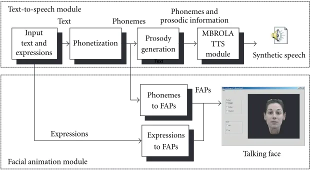
re-produce human emotions, which are input as special sym-bols (smileys) within the text. The basic system structure of the talking head system that was developed is illustrated in Figure 9.
The basic modules of the system are the text-to-speech module for speech synthesis and the facial animation module for synthesis of facial expressions during speech. Synchro-nization between these two modules, resulting to lip-speech synchronization, is guaranteed since the same phonemic de-scription of speech is used as input at both modules. More details about these two modules are provided in the follow-ing subsections.
4.1. Text-to-speech module
nique. Both algorithms produce speech by concatenating el-ementary speech units called diphones. Unlike TD-PSOLA, MBROLA makes use of a diphone database specially adapted to the requirements of the synthesizer, and obtained after a complex processing (actually, a hybrid harmonic/stochastic analysis-synthesis) of an original diphone database (i.e., a database composed of speech samples). The resulting synthesis technique takes advantage of the flexibility of para-metric speech models while keeping the computational sim-plicity of time-domain synthesizers [10]. The MBROLA sys-tem actually provides only the DSP component of a speech synthesizer (see Figure 10) and is based on the concatenation of diphones. It uses a list of phonemes as input, together with prosodic information (duration of phonemes and a piece-wise linear description of pitch), and produces speech sam-ples on 16 bits (linear), at the sampling frequency of the di-phone database used. The advantages of using this system are (i) it is a noncommercial product of a very successful EU
project;
(ii) it allows us to focus on the more important natural language processing module to improve the natural-ness and to add color in the synthesized voices; (iii) it allows designing truly multilingual TTS systems
by supporting already more than 24 languages, while more can be supported in the future;
(iv) it is an easy to use Windows-based application.
For the results of this paper, we have used the English MBROLA diphone database and the Greek diphone MBROLA database that has been built by Bletsas and Ser-giadis [28]. However, we have defined a set of rules to achieve phonemic analysis and used simple rules to add prosody in-formation. The design of the natural language processing module differs for each language and consists of the follow-ing stages.
A text pre-processor is used to identify different words and to identify numbers, abbreviations, acronyms, and id-iomatics and transform them into full text when needed. A lookup dictionary is used to directly provide the phonetic transcription of such words or symbols.
A phonetisation module is responsible for the auto-matic determination of the phonetic transcription of regular words. This module is used to identify the phonemes com-prising each word and estimate their duration. While the mean duration of each phoneme is a user-defined parame-ter mathematical models are used to modify the duration of each phoneme in order to achieve more natural speech syn-thesis.
An (optional) synthetic prosody generation module, which adds additional properties to the final speech signal
by the MBRDICO project [17]. The same project provides utilities for automatic training of the decision trees based on a pronunciation dictionary for English language [29]. However, we have observed that phonetisation rules in the Greek language are much simpler than the English language and that a rule-based phonetisation module could be de-signed instead. More specifically, rules are made up of four parts:
(1) The left context. (2) The text to match. (3) The right context.
(4) The phonemes to substitute for the matched text.
For each unmatched letter in a word, each rule is examined, in turn, when thetext to matchstarts with the letter in the word. If the text to match is found and the right and left con-text patterns also match, the phonemes for that rule are out-put and the procedure is repeated for the next unmatched letter. This algorithm is faster and also solves the problem of creating or finding an existing Greek phonetisation dic-tionary to train the decision tree. We have written rules to cover all possible phoneme combinations in the Greek lan-guage and the extensive tests show that results are very satis-factory.
A lookup table containing the mean duration of each phoneme is used to provide an initial value of its duration. Then, according to the position of the corresponding syllable inside the word and the possible presence of accent, its dura-tion is accordingly modified, using rules similar to those im-plemented by the MBRDICO project [17]. More specifically, in the Greek language, an accent-mark shows the accent of the word, so the corresponding prosody can be easily added, that is, the duration of the phoneme under the accent-mark is increased. Furthermore, phoneme durations are inversely proportional to the number of syllables in a word and at the end of the word the tone must fall and thus the pitch reduced by 60 Hz.
All the generated synthetic speech parameters (i.e., list of phonemes along with their durations and prosodic informa-tion) are written in a text file and are used by MBROLA to actually synthesize the speech, which is then either directly output from the speakers or stored in the disk as a sound (.wav) file.
4.2. Facial animation module
Table1: Facial expressions and corresponding symbols in the TTS
expression. In addition, there are two special high-level FAP’s that are used to describevisemesandfacial expressions:
The viseme FAP identifies 14visemes, each correspond-ing to the facial expression produced when a specific phoneme is articulated. Thus each phoneme is mapped to a viseme (although some phonemes may map to the same viseme). Visemes (as well as expressions) are characterized as high-level FAPs, since their values can be expressed in terms of standard (low level) FAPs. The visemes for the Greek phonemes are similar to the visemes for the English phonemes. Thus, we have designed a lookup table that maps Greek visemes to the corresponding English ones, or per-forms a blending of two visemes in cases that this proves to be necessary. This is supported by MPEG-4, as a Viseme FAP can specify two out of the predefined list of 14 visemes, and a factor to blend between them.
The expression FAP is used to describe emotional face expressions (e.g., joy, sadness, etc.). There are 6 such expres-sions currently supported by the MPEG-4 standard and our TTS system. We can introducefacial expressionsby using spe-cial symbols in the text, as shown in Table 1. Expression sym-bols are input as text along with a number, which defines the desired duration of the expression in ms, e.g.,\:)1000. The TTS module produces no output (silences) within the ex-pression duration. As the viseme FAP, the exex-pression FAP can specify two out of the predefined list of six basic expressions and intensity values allowing the blending of the two expres-sions.
In order to achieve a more natural facial animation the viseme or expression FAP values are attributed to specific time instants, that is, the midtime of their corresponding time interval and used as keyframes. Then an interpolation procedure is used to calculate FAP values corresponding to frames between two consecutive keyframes. For this purpose, a smoothing function is used to smooth out the transitions between two visemes (or expressions). Specifically, the third-order Hermite function is used
f(x)=2x3−3x2+ 1a1+ wherea1anda2are the FAP values corresponding to the two keyframes,x∈[0,1], andgis the desired gradient at the first keyframe (x=0). This function, also used in [15], provides very satisfactory interpolation results. The same procedure is used for Greek and English TTS.
In addition, facial movements (small head rotations and
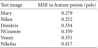
Table2: FPD method deformation error, measured in the projected positions of the feature points.
Test image MSE in feature points (pels)
Mary 0.279
eye blinking), are periodically performed by inserting spe-cific FAP sequences, along the lip movements, thus adding a higher degree of realism to the talking head.
Synchronization between the sound file produced by MBROLA and the FAP file produced by converting the phonemes to FAPs is achieved, since the durations of the phonemes are available to both the TTS and the facial ani-mation engine.
5. EXPERIMENTAL RESULTS
In Figures 11, 12, 13, 14, and 15 we provide visual results for our 3D adaptation method compared to the RBF adap-tation method. It is evident that while the RBF adapadap-tation method ensures that the given feature points are displaced at their exact required positions the natural smoothness of the human face is not maintained in all cases. This is achieved by our method (facial parts deformation—FPD) which by operating on every part separately ensures that the initial characteristics of most facial parts are maintained. The pro-posed method, although not guaranteeing displacement of the feature points at their exact required position, results to a negligible deviation from this requirement, as shown in Table 2. This is illustrated also visually in Figure 18, where an adapted with the FPD method model (this adaptation is illustrated in Figure 17) is animated presenting the seven different emotions provided by the MPEG-4 standard. In Figure 16 we illustrate the provided interface of our viewer together with some frames of the resulting talking head.
6. CONCLUSIONS
(a) FPD adaptation.
(b) RBF adaptation.
Figure11:Marytest images.
(a) FPD adaptation.
(b) RBF adaptation.
(a) FPD adaptation.
(b) RBF adaptation.
Figure13:Dimitristest images.
(a) FPD adaptation.
(b) RBF adaptation.
(a) FPD adaptation.
(b) RBF adaptation.
Figure15:Vennytest images.
Figure17: FPD adaptation onNikolastest image.
Figure18: MPEG-4 emotions onNikolastest image.
APPENDIX
The system of the four equations given in (1) can be rewritten as
This system can be given in the form
A·x=b, (A.2)
The solution to this system is found by the least squares method by the calculation of
ward a high-level interface for the design of MPEG-4 compli-ant animated faces,”IEEE Trans. Circuits and Systems for Video Technology, vol. 9, no. 2, pp. 277–289, 1999.
[4] R. Pockaj, M. Costa, F. Lavagetto, and C. Braccini, “MPEG-4 facial animation: an implementation,” inProc. International Workshop on Synthetic-Natural Hybrid Coding and 3-D Imag-ing, pp. 33–36, Santorini, Greece, September 1999.
[5] W.-S. Lee, M. Escher, G. Sannier, and N. Magnenat-Thalmann, “MPEG-4 compatible faces from orthogonal pho-tos,” inInternational Conference on Computer Animation, pp. 186–194, Geneva, Switzerland, May 1999.
[6] L. Moccozet and N. Magnenat-Thalmann, “Dirichlet free-form defree-formations and their application to hand simulation,” inInternational Conference on Computer Animation, pp. 93– 102, IEEE Computer Society, Geneva, Switzerland, 1997. [7] T. Sederberg and S. R. Parry, “Free form deformation of solid
geometric models,” inProc. SIGGRAPH ’86, pp. 151–160, Dallas, Tex, USA, August 1986.
[8] F. Pighin, J. Auslander, D. Lischinski, D. Salesin, and R. Szeliski, “Realistic facial animation using image based 3D morphing,” Tech. Rep. UW-CSE-97-01-03, University of Washington, Seattle, Wash, USA, May 1997.
[9] L. Zhang, “Automatic adaptation of a face model using action units for semantic coding of videophone sequences,” IEEE Trans. Circuits and Systems for Video Technology, vol. 8, no. 6, pp. 781–795, 1998.
[10] T. Dutoit,An Introduction to Text-To-Speech Synthesis, Kluwer Academic, Dordrecht, Netherlands, 1996.
[11] Digimask—The Face of the Future, http://www.digimask. com.
[12] LifeFX—The face of the Internet, http://www.lifefx.com. [13] N. M. Brooke, “Computer graphics synthesis of talking faces,”
inTalking Machines: Theories, Models, and Designs, G. Bailly, C. Benot, and T. R. Sawallis, Eds., pp. 505–522, North Hol-land, Elvsevier, Amsterdam, 1992.
[14] B. DeGraph and M. Wahrman, “Mike, the talking head,” Computer Graphics, vol. 11, pp. 15–17, 1988.
[15] J. Ostermann, M. Beutnagel, A. Fischer, and Y. Wang, “In-tegration of talking heads and text-to-speech synthesizers for visual TTS,” inProc. 5th International Conference on Spoken Language Processing (ICSLP-98), Sydney, Australia, November 1998.
[16] MBROLA project, http://tcts.fpms.ac.be/synthesis/mbrola. html.
[17] MBRDICO project, http://tcts.fpms.ac.be/synthesis/mbrdico/. [18] A. Al-Qayedi and A. F. Clark, “An algorithm for face and facial-feature location based on grey-scale information and facial geometry,” inProc. IEEE International Conference on Im-age Processing and its Applications, vol. 2, pp. 625–629, Manch-ester, UK, July 1999.
[19] T. C. Chang and T. S. Huang, “Facial feature extraction from color images,” in12th International Conference on Pattern Recognition, vol. 2, pp. 39–43, Israel, October 1994.
[20] M. Reinders, P. J. L. van Beek, B. Sankur, and J. C. A. van der Lubbe, “Facial feature localization and adaptation of a generic face model for model based-coding,”Signal Processing: Image Communication, vol. 7, no. 1, pp. 57–74, 1995.
[24] D. W. Marquardt, “An algorithm for least squares estimation of non-linear parameters,” SIAM J. Appl. Math., vol. 11, pp. 431–441, 1963.
[25] The minpack library, Netlib repository, http://www.netlib. org/minpack/.
[26] G. A. Abrantes and F. Pereira, “MPEG-4 facial anima-tion technology: survey, implementaanima-tion, and results,” IEEE Trans. Circuits and Systems for Video Technology, vol. 9, no. 2, pp. 290–305, 1999.
[27] F. Pighin, J. Hecker, D. Lischinski, R. Szeliski, and D. H. Salesin, “Synthesizing realistic facial expressions from pho-tographs,” Computer Graphics, vol. 32, pp. 75–84, August 1998, Annual Conference Series.
[28] Esopos, Hellenic TTS System, http://esopos.ee.auth.gr. [29] V. Pagel, K. Lenzo, and A. W. Black, “Letter to sound rules
for accented lexicon compression,” inProc. 5th International Conference on Spoken Language Processing (ICSLP-98), Syd-ney, Australia, November 1998.
Nikos Grammalidis is an Associate Re-searcher in the Informatics and Telematics Institute. He received his B.S. and Ph.D. de-grees in electrical and computer engineer-ing from the Aristotle University of Thessa-loniki, in 1992 and 2000, respectively. Prior to his current position, he was a Researcher in 3D Imaging Laboratory at the Aristo-tle University of Thessaloniki. His main re-search interests include image compression,
3D data processing, multimedia image communication, 3D mo-tion estimamo-tion, stereo and multiview image sequence coding. His involvement with those research areas has led to the coauthoring of more than 10 articles in refereed journals and more than 25 papers in international conferences. Since 1992, he has been involved in more than 10 projects, funded by the EC and the Greek Ministry of Research and Technology.
Nikos Sarriswas born in Athens, Greece in 1971. He received his Master of Engineer-ing degree in computer systems engineer-ing from the University of Manchester In-stitute of Science and Technology (UMIST), in 1995. He has worked as a Research As-sistant in the Information Processing Labo-ratory of the Aristotle University of Thessa-loniki for 4 years, where he participated in several national and international projects.
Fani Deligianni received her B.S. degree (Diploma) in electrical and computer engi-neering from Aristotle University of Thes-saloniki, Greece in 2000. In 2001, she has worked as a Researcher in the 3D Imag-ing Laboratory at the Aristotle University of Thessaloniki. Her main interests include 3D computer graphics, facial animation, and MPEG-4 coding. Ms. Deligianni is currently pursuing her M.S. degree in advanced com-puting at Imperial College, London.
Michael G. Strintzisreceived the Diploma degree in electrical engineering from the National Technical University of Athens, Athens, Greece in 1967, and the M.A. and Ph.D. degrees in electrical engineering from Princeton University, Princeton, NJ, USA in 1969 and 1970, respectively. He then joined the Electrical Engineering Depart-ment at the University of Pittsburgh, Pitts-burgh, Pa., USA, where he served as