P-CORDIC: A Precomputation Based Rotation
CORDIC Algorithm
Martin Kuhlmann
Broadcom Corporation, Irvine, CA 92619, USA Email: [email protected]
Keshab K. Parhi
Department of Electrical and Computer Engineering, University of Minnesota, Minneapolis, MN 55455, USA Email: [email protected]
Received 30 August 2001 and in revised form 14 May 2002
This paper presents a CORDIC (coordinate rotation digital computer) algorithm and architecture for the rotation mode in which the directions of all micro-rotations are precomputed while maintaining a constant scale factor. Thus, an examination of the sign of the angle after each iteration is no longer required. The algorithm is capable to perform the CORDIC computation for an operand word-length of 54 bits. Additionally, there is a higher degree of freedom in choosing the pipeline cutsets due to the novel feature of independence of the iterationsiandi−1 in the CORDIC rotation.
Keywords and phrases:CORDIC, computer arithmetic, constant scale factor, precomputation, rotation mode.
1. INTRODUCTION
CORDIC (coordinate rotation digital computer) [1, 2] is an iterative algorithm for the calculation of the rotation of a 2-dimensional vector, in linear, circular, or hyperbolic coor-dinate systems, using only add and shift operations. It has a wide range of applications including discrete transforma-tions such as Hartley transform [3], discrete cosine form [4], fast Fourier transform (FFT) [5], chirp Z trans-form (CZT) [6], solving eigenvalue and singular value prob-lems [7], digital filters [8], Toeplitz system and linear system solvers [9], and Kalman filters [10]. It is also able to detect multiuser in code division multiple access (CDMA) wireless systems [11].
The CORDIC algorithm consists of two operating modes, the rotation mode and the vectoring mode, respec-tively. In the rotation mode, a vector (x, y) is rotated by an angleθto obtain the new vector (x∗, y∗) (see Figure 1). In every micro-rotationi, fixed angles of the value arctan(2−i)
are subtracted or added from/to the angle remainderθi, so
that the angle remainder approaches zero. In the vectoring mode, the length Rand the angle towards thex-axisαof a vector (x, y) are computed. For this purpose, the vector is ro-tated towards thex-axis so that they-component approaches zero. The sum of all angle rotations is equal to the value of α, while the value of the x-component corresponds to the lengthRof the vector (x, y). The mathematical relations for
y∗
y
θ α
x∗ x R
Figure1: The rotation and vectoring mode of the CORDIC algo-rithm.
the CORDIC rotations are as follows:
xi+1=xi+m·σi·2−i·yi,
yi+1=yi−σi·2−i·xi,
zi+1=zi− 1
m·σi·arctan
√
m2−i,
(1)
the choice of rectangular (m=0), circular (m=1), or hy-perbolic (m= −1) coordinate systems. The required micro-rotations are not perfect micro-rotations, they increase the length of the vector. In order to maintain a constant vector length, the obtained results have to be scaled by a scale factorK. Nev-ertheless, assuming consecutive rotations in positive and/or negative directions, the scale factor is constant and can be precomputed according to
The computation of the scale factor can be truncated after n/2 iterations because the multiplicands in the lastn/2 itera-tions are 1 due to the finite word-length and do not affect the final value ofK1,
There are two different approaches for the computation of the CORDIC algorithm. The first one uses consecutive rotations in positive and/or negative direction, where the weight of each rotation is 1. Hence,σiis either−1 or 1,
de-pending on the sign of the angle remainderz(i). In every it-eration a significant amount of time is used to examine the most significant bit in case of a binary architecture or the most significant three digits of a redundant architecture to predict the sign ofz(i) and hence the rotation directionσi. In
comparison to the CORDIC implementations with constant scale factor, other implementations use a minimally redun-dant radix-4 or an even higher radix number representation [12, 13, 14]. These architectures make use of a wider range ofσi. In case of a minimally redundant radix-4 architecture,
σi ∈ {−2,−1,0,1,2}. By using this numbering system, the
number of iterations can be reduced. However, the compu-tation time per iteration increases, since it takes more time to differentiate between five different rotation direction values and to generate five different multiples of arctan(2−i). The
scale factor also becomes variable and has to be computed every time, due to the absence of consecutive rotations lead-ing to an increase in area.
To speed up the computation time of the CORDIC algo-rithm, either the number of iterations or the delay of each it-eration have to be minimized. The proposed algorithm intro-duces a novel approach, in which the rotation direction can be precomputed by adding the rotation angleθ, a constant and a variable adjustment which is stored in a table. Hence, a significant speedup of the delay per iteration is obtained. Since all rotation directions are known before the actual rota-tion begins, more than one rotarota-tion can also be performed in one iteration leading to a reduction in latency. The proposed architecture also eliminates the z-datapath and reduces the area of the implementation.
This paper is organized as follows. Section 2 presents the theoretical background for the novel CORDIC algorithm for rotation mode and Section 3 presents the novel architecture.
Section 4 performs an evaluation of different CORDIC ar-chitectures while Section 5 concludes the paper.
2. THE NOVEL CORDIC ALGORITHM
2.1. Mathematical derivation using Taylor series
The summation of all micro-rotation with their correspond-ing weightσiis equivalent to the rotation angleθ
θ=
traction of the micro-angles θi. Since consecutive rotations
are employed, the scale factor is constant. The value ofσcan be interpreted as a number in radix-2 representation. The goal of the proposed method is to compute the sequence of the micro-rotation without performing any iteration. To ac-complish this, σi is recoding as 2di−1 leading to a binary
representation in which a zero corresponds to the addition of a micro-angle [15, 16]. This allows the use of simple bi-nary adders. Adding and subtracting 2−ito (4) results in
θ= Solving (8) fordresults in
d=0.5θ+ 0.5c1+ sign(θ)·
whereccorresponds to 0.5c1. Table 1 shows the values of the partial offsetsifor the first 10 values ofiand indicates that
the value ofidecreases approximately by a factor of 8 with
increasingi. Hence, the summation ofdiican be limited to
Table1: The values ofiof the first 10 values ofi.
Iterationi Partial offseti
0 0.214601836602551690 1 3.635239099919176e-02 2 5.021336873135844e-03 3 6.450054532385649e-04 4 8.119000404265152e-05 5 1.016656973172375e-05 6 1.271379523169197e-06 7 1.589398988887035e-07 8 1.986803302817237e-08 9 2.483521181314878e-09
Rather than storing the partial offsetsiand computing
the sum over alliof the productdii,δ =
n/3
i=1diican be
precomputed and stored. Hence, the only difficulty consists of determining which offset corresponds to the inputθ. This can be achieved by comparing the inputθwith a reference angleθref. The reference anglesθrefcorrespond to the sum-mation of the firstn/3 micro-rotation. To be certain to obtain the correct offset,θhas to be larger than the reference angle θref. All reference angles are stored in a ROM and are accessed by the most significantn/3 bits ofθ. In addition to the refer-ence angles, the values ofδare stored. In case of a negative differenceθref−θ, the correspondingδis selected, otherwise the next smaller value ofδ is chosen to be subtracted from θ+c−sign(θ)·0.
Example1. Assuming we have a word-length of 16 bits and θ = 0.9773844. According to Table 2, θref corresponds to 0.97337076 andδ=0.03644375. Hence,dis computed as
d=0.5·θ+ 1−0.5·c+
n/3
i=0 dii
=0.5·0.9773844 + 1.08624513 + 0.03644375
=1.6113811=1.10011100100000112, σ=11¯1¯1111¯1¯11¯1¯1¯1¯1¯111.
(11)
2.2. High precision
By using a mantissa of n = 54 bits (corresponding to the floating point precision), the ROM for storing all offsets would require 218entries. This is rather impractical since the required area to implement the ROM will exceed by far the area for the CORDIC implementation. To reduce the area for the ROM,δcan be split into two parts,
δ=δROM+δr, (12)
where δROM is stored in a ROM while δr is computed. By
examining the Taylor series expansion of arctan(2−i), it
be-comes obvious that the partial offsetfor iterationiandi+ 1
Table2: The reference angles of the rotation mode and their corre-sponding values ofδfor an operand word-length of 16 bits.
θref δ
−0.01640412 0.00008119 0.04607554 0.00009136 0.10746824 0.00064501 0.16994791 0.00065517 0.23230586 0.00072620 0.29478553 0.00073636 0.34871558 0.00502134 0.41119525 0.00503150 0.47355320 0.00510253 0.53603287 0.00511269 0.59742557 0.00566634 0.65990524 0.00567651 0.72226319 0.00574753 0.78474286 0.00575770 0.78605347 0.03635239 0.84853314 0.03636256 0.91089109 0.03643358 0.97337076 0.03644375 1.03476346 0.03699740 1.09724313 0.03700756 1.15960108 0.03707859 1.22208075 0.03708875 1.27601080 0.04137373 1.33849046 0.04138389 1.40084842 0.04145492 1.46332808 0.04146508 1.52472079 0.04201873 1.58720045 0.04202890
corresponds to
i=2−i−arctan
2−i =
−2−3i
3 +
2−5i
5 −
2−7i
7 +
2−9i
9 − · · ·
, (13)
i+1=2−i−1−arctan
2−i−1 (14)
=
−2−3i−3
3 +
2−5i−5
5 −
2−7i−7
7 +
2−9i−9 9 − · · ·
(15)
=2−3
−2−3i
3 +
2−5i−2
5 −
2−7i−4
7 +
2−9i−6 9 − · · ·
.
(16)
By comparing (13) and (16), it can be seen that (13) is about 23times larger than (16). Assuming a word-length ofnbits andi >n/5 −2, the factor is 23. Hence, the term
n/5−1=
the remaining offsetδris computed as
Assume that we have a word-length of 50 bits and θ =
0.977384381116. Using the most significant 9 bits of θ, δROM = 0.03644501895249 can be obtained. Hence, d is computed according to
d=0.5·θ+ 1−0.5·c+δROM+δr
=0.5·0.97738438111600 + 1.08624514683872 + 0.03644501895249 + 2.483521181241566e
−09·1 + 2−18+ 2−21+ 2−24
=1.61138235883274
=1.1001110010000011100011011
1100100100010011011100012. (18)
2.3. The rotation mode in hyperbolic coordinate
systems
Similar to the circular coordinate system, a simple corre-lation between the input angleθ and the directions of the micro-rotation can be obtained. Due to the incomplete rep-resentation of the hyperbolic rotation angleθi, some
itera-tions have to be performed twice. In [2], it was recommended that every 4th, 13th, (3k+ 1)th iteration should be repeated to complete the angle representation.
Similar to the rotation mode in circular coordinate sys-tem, the rotation angleθis equivalent to the summation of all micro-rotation with their corresponding weight. This leads to
Performing a Taylor series expansion and applyingσi=2di−
1 results in Since these extra rotation are not known in advance, an ef-ficient high precision VLSI implementation is not possible. However, for signal processing applications using a word-length of less than 13 bits, the ROM size corresponds to only 14 entries.
3. THE NOVEL ROTATION-CORDIC ARCHITECTURE
For an implementation with the operand word-length of nbits, the pre-processing part consists of a ROM of 2n/5−2
entries in which the reference anglesθrefand the correspond-ing offsetsδare stored, respectively (see Figure 2). To avoid a second access to the ROM in case ofθref> θthe next smaller offsetδk−1is additionally stored in thekth entry of the ROM. The ROM is accessed by then/5−2MSB bits ofθ. A binary tree adder computes, whetherθis smaller or larger than the chosen reference angleθrefand selects the corresponding off -set (eitherδkorδk−1). Using a 3 : 2 compressor and another
fast binary tree adder, the two required additions to obtain dapprox=0.5θ+c2+δROMcan be performed, wherec2 corre-sponds toc+sign(θ)0. Using the bitsdn/5−1todn/3,δrcan
be computed according to (17) and has to be added todapprox. For the worst case scenario, there is a possible ripple from the bit d3(n/5−1) to the bitd(n/5)which would call for a time consuming ripple adder. However, by employing an extra ro-tation for d3(n/5−1)−1 this limitation can be resolved. This extra rotation corresponds to the overflow bit of the addition from the bitsdapprox−3(n/5−1)···nandδr. The additional rotation
also does not affect the scale factor, since 3(n/5 −1)> n/2. For a precision ofn≤ 16 bits, there are less than 32 offsets which can be stored in a ROM and the additional overhead to computeδrcan be removed.
The alternative architecture can be chosen by realizing that the directions of the micro-rotations are required in a most significant bit first manner (see Figure 2). As in the pre-vious architecture, a fast binary adder is employed to deter-mine which offset has to be selected. A redundant sign digit adder adds 0.5θ, c, andδROM and an on-the-fly converter starts converting resulting into the corresponding binary representation. Normally, the most significant bit cannot be determined until the least significant digit is converted. How-ever, such worst cases do not exist in the CORDIC imple-mentation, due to the redundant representations of the an-gles arctan(2−i), where
as opposed to the binary representation
2−i>
∞
k=i+1
2−k. (22)
θ
ROM
θref
θ
δkδk−1 2 words Fast adder
Muxes sign
δROM δr
c2 θ
Redundant adder
εn/5−2∗d[n/5−2 :n/3]
x y
On-the-fly converter σ CORDIC rotations
x∗ y∗
Figure2: The novel architecture for the rotation mode.
Table3: The maximal number of consecutive rotation in the same direction.
i θi l−1 i θi l−1 i θi l−1
0 45 3 2 14.04 6 4 3.58 10 1 26.57 5 3 7.13 8 5 1.79 12
iteration has to be rotated into the opposite direction. This happens if the angle remainder zi ≈ 0. Table 3 shows the
maximum number of consecutive unidirectional rotations depending on the iteration numberi. This limitation leads to a reduction in the complexity of the online converters and its most significant bits can already be used to start the rota-tions in thex/ydatapath.
Example2. Assuming an angleθ =0.001. Hence, the angle remainderθicorrespond to
θ0=0.001,
θ1=θ0−arctan(1)= −0.7844, θ2=θ1+ arctan(0.5)= −0.3208, θ3=θ2+ arctan(0.25)= −0.0758, θ4=θ3+ arctan(0.125)=0.0486.
(23)
The next rotation has to be performed in the negative direc-tions, sinceθ4>0. Hence, it is not possible to obtain rotation sequence likeσ0···4=01111 but it has to beσ0···4=01110.
3.1. Evaluation of thez-datapath
Delay analysis
In this paper, we assume a similar delay model as proposed in [14]. Nevertheless in [14], the unit delay is set to a gate delay
while in our evaluation the unit delay is set to a full-adder de-lay. Hence, the delays for 2-input (NAND, NOR) gate, XOR, multiplexer, register, and full-adder are 0.25, 0.5, 0.5, 0.5, and 1tFA.
The determination of which offset has to be chosen con-sists of the delay of the decoder, the ROM, a fast binaryn -bit tree adder and a multiplexer. Assuming a delay of log2(m) gate delays for the decoder, wheremcorresponds to the num-ber of rows in the ROM (m < log2(n) + 1), one for the word-line driver and another for the ROM, log2(n)·tMux for the fast binary adder and 0.5·tFA for the multiplexer, we can obtain the correct value of δROM after a delay of (0.5 log2(n) + 1 + 0.25 log2(log2(n)))·tFA.
A 3 : 2 compressor can be employed to reduce the num-ber of partial products to two. An additional fast binary tree adder can compute the final value ofdapprox. Hence, the entire delay to obtaindapproxcorresponds to
0.5 log2(n) + 1 + 0.25 log2log2(n)
+ 1 + 0.5 log2(n)·tFA=
log2(n) + 2.25·tFA. (24)
After obtaining the bitsdn/5−1todn/3,δrcan be computed.
Since the value ofδris smaller than 2−3(n/5−1)and the value
ofdapprox+δris not required before 23(n/5)tFAthe computa-tion ofδris not in the critical path.
Alternatively to the 3 : 2 compressor and the tree adder, a minimally redundant radix-4 sign digit adder can be em-ployed which has a delay of two full-adders. Hence, all output digits are available after these two full-adder delays. An addi-tional on-the-fly converter converts the digits into its equiva-lent binary representation starting with the MSD. It requires a delay of multiplexer and four NANDs/NORs to convert one digit which results in 1.5tFAper digit (1 digit=2 bits). The last digit is converted after a delay of (n/2 + 1)·1.5tFA. As already described in Table 3, bitn/3 is stable as soon as the last digit (corresponding to bit n) has been converted. Hence, the n/3 rotation can be performed after a delay of (n/2 + 1)·1.5tFA. Therefore, the iterationsi=0 can already be performed after a delay of (n/2 + 1)·1.5tFA−n/3·2tFA= (1/12·n+ 1)tFA. Note that the conversion of one redundant digit is performed faster than the addition/subtraction of the x/y datapath. Hence, an initial delay of (1/12·n+ 1)tFA+ (log2(n) + 2.25)tFA=(1/12·n+ log2(n) + 3.25)tFAhas to be added to the delay of thex/ydatapath.
Area analysis
the examination of the most significant three digits, about 5700AFAare required.
The proposed architecture utilizes a ROM of word-length nand 2n/5−2entries, requiring an area ofn·2n/5−2·A
FA· 1/50 resulting in 552AFAfor a word-length of 54 bits. The im-plementation of the decoders can be done in multiple ways. NOR based decoders with precharge lead to the fastest imple-mentation. However, the decoder area becomes larger. The decoder size per word-line corresponds toAdec = 0.83AFA. Since 2n/5−2decoders are required, the area for all decoder corresponds to Adec,total = 0.83·2n/5−2 = 424AFA, as-suming a 54 bit word-length. The ROM has to store θref, δk, andδk−1. This results in a total area for the ROM and
the decoder of about 2080AFA. The computation of δr
re-quiresn/3−n/5 + 2 =2n/15 + 2 rows of CSA (carry-save-adders) and Muxes and a final fast binary tree adder. Note that each row of CSA adders and Muxes only consists of (n−3n/5 + 6 = 2n/5 + 6) bits (the more significant bits are zero). The required area corresponds to 10·27AFA+ 10·27Amuxand 5·27AFA, respectively. Hence, the compu-tation ofδr requires 540AFA. Moreover, the two redundant
sign digit adder require 2n·AFA, while the converter con-sists of about (0.5n2+n)A
mux. This corresponds to 108 and 696AFA for a word-length of 54 bits. This makes a total of 3426AFA, which is about 60% of the z-datapath previously employed.
3.2. Evaluation of thex/ydatapath
In the firstn/2 micro-rotations, the critical path of thex/y rotator part consists of a multiplexer and a 4 : 2 compres-sor, which has a combined critical path of 2 full-adders. The lastn/2 micro-rotations can be performed only usingn/4 it-erations, since Booth encoding can be employed. However, the delay of the selection for the multiple of the shiftedx/y components requires slightly more time, resulting in a delay of about one full-adder delay. The delay for the 4 : 2 com-pressor remains 1.5 full-adder. Hence, the critical path of the entirex/yrotator part consists ofn/2·2tFA+n/4·2.5·tFA= 1.625n·tFA. Note that the direction of the first iteration is already known; hence, the first iteration is not in the critical path. Therefore, the critical path of the entirex/yrotator part consists of (1.625n−2)tFA.
As an example, for a word-length ofn=16 bits, thex/y datapath delay and the entire delay of the CORDIC algorithm corresponds to 24 and 32.5 full-adder delays, respectively.
3.3. Scale factor compensation
Since the scale factor is constant, thexandyvalues can al-ready be scaled while the rotation direction is being com-puted. The scaling requires an adder of word-length (n+ log2(n)) bits. Using a binary tree adder, this results in a de-lay of log2(n+ log2(n))·tMux. For the scale factor, a CSD (canonic signed digit) representation can be used, leading to at most n/3 nonzero digits. Applying a Wallace-tree for the partial product reduction, the total delay of the scal-ing results into (0.5 log2(n+ log2(n)) + log1.5(n/3))·tFA < (1/12·n+ log2(n) + 3.25)·tFA =tinitial. Hence, the scaling
of thexandycoordinates does not affect the total latency of the novel algorithm.
4. OVERVIEW OF PREVIOUSLY REPORTED CORDIC ALGORITHMS
The delay of every iteration can be decomposed into two dif-ferent time delays,td,σandtd,xy, wheretd,σcorresponds to the
time delay to predict the new rotation direction whiletd,xy
corresponds to the time delay of the multiplexer/add struc-ture of thex/ydatapath. Various implementations have been proposed to obtain a speedup of the CORDIC algorithm. Im-provements have been especially made in the reduction of td,σ.
In [17], the angle remainder has been decomposed every k=3k+ 1 iteration. From the given angleθ, the first four ro-tation directions can be immediately determined. After per-forming the corresponding addition/subtraction of the terms σi·αifrom the input angleθusing CSA arithmetic, a fast
bi-nary tree adder computes the nonredundant result z4. The bits 4 to 13 ofz4deliver the rotation directionσ4toσ13which are used to perform the rotation in thex/ydatapath and the computation of the next angle remainderz40. Hence, a low latency CORDIC algorithm is obtained. However, a signif-icant reduction in latency is achieved at the cost of an ir-regular design. Furthermore, it is difficult to perform aπ/2 initial rotation or the rotation of index i = 0 for circular coordinates, as it would force a conversion from redundant to conventional arithmetic for thezcoordinate just after the first micro-rotation which is costly in time and area. Hence, this parallel and nonpipelined architecture only converges in the range of [−1,1]. The overall latency of this architec-ture corresponds to about 2n+ log3(n) + log2(n) full-adder delay.
In [18], a direct correlation between thezremainder af-tern/3rotations and the remaining rotation direction have been shown. Hence, no more examination of the direction of the micro-rotation has to be performed leading to a consider-able reduction in latency. However, in the firstn/3iteration a conventional method has to be employed.
In [19], the directions of the micro-rotation have been recoded using an offset binary coding (OBC) [20]. The ob-tained correlation is approximately piecewise linear since small elementary angles can be approximated by a(i) = arctan(2−i)≈s·2n−i−2, wheresis the slope of the linearity. This is valid fori≥ m, wheremis an integer which makes the approximation tolerable (normallym= n/3). Hence, the following correlation can be obtained:
n−1
i=m
σi2αi≈s· n−1
i=m
σi·2−i−1. (25)
By performing some arithmetic computations, the following correlation of the rotation direction can be obtained:
n−1
i=0
σi·2−i= n−1
i=0
σi·2−i−1− n−1
i=m
σi·
2α(i)
Hence, a multiplication by the inverse of the slope sis re-quired. This multiplication can be simplified to two stages of addition for an operand word-length of 9 bits. However, in most digital signal processing application, the operands have a word-length of up to 16 bits. Hence, for those applica-tions, the presented method requires more stages of addition to compensate the multiplication resulting in a more com-plex implementation and an increase in delay.
In [21], a double rotation method is introduced which compensates for the scale factor while performing the regular x/y rotations. However, due to the double rotation nature of this method,td,xyis increased to about twice its original
value.
To reduce the latency of the CORDIC operation, [22] proposed an algorithm using online arithmetic. However, this results in a variable scale factor. This drawback is re-moved in [23]. In every iteration a significant amount of time is used to examine the most significant three digits to pre-dictσi. The employed random logic requires a delay of about
1.5 full-adder delays. Since thex/ydatapath consists of a 4-2 compressor, it requires also a delay of 2 full-adders. Hence, the overall iteration delay corresponds to 3.5 full-adder de-lays. To maintain a constant scale factor, consecutive rota-tions are required in the first n/2, where ncorresponds to the word-length of the operands. For the computation of the lastn/2 bits, Booth encoding can be employed reducing the number of iterations by a factor of 2. However, the selection of multiple of the shiftedxandyoperands requires an ad-ditional multiplexer delay and increases the overall iteration delay to 4 full-adder delays. Hence, the number of iteration is equivalent to 0.75nwhich corresponds to a total latency of 3nfull-adders (this does not include the scale operation and the conversion).
Other implementations like [24] remove the extra rota-tions by a branching mechanism in case that the sign of the remainder cannot be determined (most significant three dig-its are zero). Hence, no extra-rotations are required while the required implementation area is doubled. Nevertheless, the most significant three digits (or most significant six bits) still have to be examined for the prediction of the next rotation direction. In [25], the double step branching CORDIC algo-rithm is introduced which performs two rotations in a single step. Nevertheless, this method requires an examination of the most significant six digits to detect two rotation direc-tions. Since some of the digits can be examined in parallel, the delay increases only to 2tFA. The computation time of a double rotation in thex/ydatapath is slightly reduced com-pared to two normalx/yrotations. Hence, the total amount of computation time corresponds to 0.5n(2tFA+ 3tFA) = 2.5tFA.
In [26], the signs of all micro-rotations are computed se-rially. However, a speed up of the sampling rate is achieved by separating the computation of the sign and the magnitude of everyzioryiremainder. The sign of every remainder is
com-puted by a pipelined carry-ripple adder (CRA) leading to an initial latency ofnfull-adders before the first CORDIC rota-tion can be performed. Nevertheless, after this initial latency, the following signs can be obtained with a delay of only one
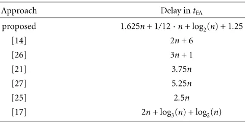
Table4: An overview between the proposed algorithm and other CORDIC implementations.
Approach Delay intFA
proposed 1.625n+ 1/12·n+ log2(n) + 1.25
[14] 2n+ 6
[26] 3n+ 1
[21] 3.75n
[27] 5.25n
[25] 2.5n
[17] 2n+ log3(n) + log2(n)
full-adder. This leads to an overall latency of 3nfull-adders delays.
In comparison to the CORDIC implementations with constant scale factor, other implementations use a minimally redundant radix-4 or an even higher radix number repre-sentation [12, 13, 14]. By using this number system, the number of iterations can be reduced. However, the predic-tion of the σi becomes more complicated, since there are
more possible values forσi. In addition, the scale factor
be-comes variable and has to be computed every time, due to the absence of consecutive rotations. An online computa-tion of the scale factor and a parallel scaling of the x and yoperands can be achieved. Depending of the use of CSA or fast carry-propagate-adders (CCLA), the number of it-erations can be reduced to 2n/3+ 4 andn/2 + 1, respec-tively. The iteration delaytd,CSAof the architecture using CSA adders corresponds to the same delay as already described for the last n/2 iteration in the constant scale factor using Booth-encoding, while the architecture employing the fast CCLA adders requires 1.5·d,CSA[14]. Hence, the overall la-tency of these CORDIC algorithm using a minimally redun-dant radix-4 digit set corresponds to about 2n full-adder delays.
Table 4 provides a delay comparison between the pro-posed algorithm and other CORDIC implementations. Some of the delays have been taken from [14, 17, 26].
5. CONCLUSION
ACKNOWLEDGMENT
This work was supported by the Defense Advanced Research Projects Agency under contract number DA/DABT63-96-C-0050. Prof. Parhi is on leave from the Department of Elec-trical and Computer Engineering of the University of Min-nesota, Minneapolis, MN, USA.
REFERENCES
[1] J. E. Volder, “The CORDIC trigonometric computing tech-nique,” IRE Transactions on Electronic Computers, vol. 8, no. 3, pp. 330–334, 1959.
[2] J. S. Walther, “A unified algorithm for elementary functions,” inProc. Spring Joint Computer Conference, vol. 38, pp. 379– 385, 1971.
[3] L. W. Chang and S. W. Lee, “Systolic arrays for the discrete Hartley transform,”IEEE Trans. Signal Processing, vol. 39, no. 11, pp. 2411–2418, 1991.
[4] W.-H. Chen, C. H. Smith, and S. C. Fralick, “A fast compu-tational algorithm for the discrete cosine transform,” IEEE Trans. Communications, vol. 25, no. 9, pp. 1004–1009, 1977. [5] A. M. Despain, “Fourier transform computers using CORDIC
iterations,”IEEE Trans. on Computers, vol. 23, no. 10, pp. 993– 1001, 1974.
[6] Y. H. Hu and S. Naganathan, “A novel implementation of chirp Z-transform using a CORDIC processor,” IEEE Trans-action on Acoustics, Speech, and Signal Processing, vol. 38, no. 2, pp. 352–354, 1990.
[7] M. Ercegovac and T. Lang, “Redundant and on-line CORDIC: Application to matrix triangularization and SVD,” IEEE Trans. on Computers, vol. 39, no. 6, pp. 725–740, 1990. [8] P. P. Vaidyanathan, “A unified approach to orthogonal
digi-tal filters and wave digidigi-tal filters, based on LBR two-pair ex-traction,” IEEE Trans. Circuits and Systems, vol. 32, no. 7, pp. 673–686, 1985.
[9] Y. H. Hu and H. M. Chern, “VLSI CORDIC array structure implementation of Toeplitz eigensystem solver,” inProc. IEEE Int. Conf. Acoustics, Speech, Signal Processing, pp. 1575–1578, April 1990.
[10] T. Y. Sung and Y. H. Hu, “Parallel VLSI implementation of Kalman filter,” IEEE Trans. on Aerospace and Electronics Sys-tems, vol. 23, pp. 215–224, March 1987.
[11] H. V. Poor and X. Wang, “Code-aided interference sup-pression for DS/CDMA communications—Part I: Interfer-ence suppression capability,” IEEE Trans. Communications, vol. 45, no. 9, pp. 1101–1111, 1997.
[12] C. Li and S. G. Chen, “A radix-4 redundant CORDIC algo-rithm with fast on-line variable scale factor compensation,” inInternational Symposium on Circuits and systems, pp. 639– 642, Hong Kong, June 1997.
[13] R. Osorio, E. Antelo, J. Villalba, J. D. Bruguera, and E. L. Za-pata, “Digit on-line large radix CORDIC rotator,” inProc. Int. Conf. Application-Specific Array Processors, pp. 246–257, Strasbourg, France, July 1995.
[14] J. Villalba, J. Hidalgo, E. L. Zapata, E. Antelo, and J. D. Bruguera, “CORDIC architectures with parallel compensa-tion of the scale factor,” inProc. Int. Conf. Application Specific Array Processors, pp. 258–269, Strasbourg, France, July 1995. [15] M. Kuhlmann and K. K. Parhi, “A high-speed CORDIC
al-gorithm and architecture for digital signal processing appli-cations,” inProc. 1999 IEEE Workshop on Signal Processing Systems: Design and Implementation, pp. 732–741, Taipei, Tai-wan, October 1999.
[16] M. Kuhlmann and K. K. Parhi, “A new CORDIC rotation method for generalized coordinate systems,” inProc. 1999
Asilomar Conf. on Signals, Systems and Computers, Pacific Grove, Calif, USA, October 1999.
[17] D. Timmermann, H. Hahn, and B. J. Hosticka, “Low latency time CORDIC algorithms,” IEEE Trans. on Computers, vol. 41, no. 8, pp. 1010–1015, 1992.
[18] S. Wang, V. Piuri, and E. Swartzlander, “Hybrid CORDIC algorithms,” IEEE Trans. on Computers, vol. 46, no. 11, pp. 1202–1207, 1997.
[19] S. Nahm and W. Sung, “A fast direction sequence gen-eration method for CORDIC processors,” in Proc. IEEE Int. Conf. Acoustics, Speech, Signal Processing, pp. 635–638, Munich, Germany, April 1997.
[20] N. Demassieux and F. Jutand,VLSI Implementation for Image Communications, chapter 7, P. Pirsch, Ed., Elsevier Science, New York, NY, USA, 8th edition, 1993.
[21] N. Takagi, T. Asada, and S. Yajima, “Redundant CORDIC methods with a constant scale factor for sine and cosine com-putation,” IEEE Trans. on Computers, vol. 40, no. 9, pp. 989– 995, 1991.
[22] H. X. Lin and H. J. Sips, “On-line CORDIC algorithms,”IEEE Trans. on Computers, vol. 39, no. 8, pp. 1038–1052, 1990. [23] R. Hamill, J. McCanny, and R. Walke, “On-line CORDIC
al-gorithm and VLSI architecture for implementing QR-array processors,” to be published inJournal of VLSI Signal Pro-cessing, 1999.
[24] J. Duprat and J.-M. Muller, “The CORDIC algorithm: New results for fast VLSI implementation,” IEEE Trans. on Com-puters, vol. 42, no. 2, pp. 168–178, 1993.
[25] D. S. Phatak, “Double step branching CORDIC: A new al-gorithm for fast sine and cosine generation,” IEEE Trans. on Computers, vol. 47, no. 5, pp. 587–602, 1998.
[26] H. Dawid and H. Meyr, “The differential CORDIC algorithm: Constant scale factor redundant implementation without cor-recting iterations,” IEEE Trans. on Computers, vol. 45, no. 3, pp. 307–318, 1996.
[27] J.-A. Lee and T. Lang, “A constant-factor redundant CORDIC for angle calculation and rotation,”IEEE Trans. on Computers, vol. 41, no. 8, pp. 1016–1025, 1992.
Martin Kuhlmann received his Diplome Ing´enieur and Ph.D. degrees in electrical en-gineering from the University of Technol-ogy Aachen, Germany in 1997 and from the University of Minnesota in 1999, respec-tively. Currently, he is a staffdesign engi-neer at Broadcom Corporation, Irvine, CA, USA. His research interests include com-puter arithmetic, digital communication, VLSI design, and deep-submicron crosstalk.
Keshab K. Parhiis a distinguished McK-night University Professor of Electrical and Computer Engineering at the University of Minnesota, Minneapolis, where he also holds the Edgar F. Johnson Professorship. He received the B.Tech., M.S.E.E., and Ph.D. degrees from the Indian Institute of Technology, Kharagpur (India) (1982), the University of Pennsylvania, Philadelphia