ISSN(Online): 2320-9801
ISSN (Print): 2320-9798
I
nternational
J
ournal of
I
nnovative
R
esearch in
C
omputer
and
C
ommunication
E
ngineering
(An ISO 3297: 2007 Certified Organization)
Vol. 4, Issue 8, August 2016
Hand Movement Controlled Computer Mouse
Interface
Shivani Pawar1, Prof. A. M. Rawate2
Student, Dept. of Electronics &Tele-communication, CSMSS, Aurangabad, India 1 Professor, Dept. of Electronics& Tele-communication, CSMSS, Aurangabad, India 2
ABSTRACT: This paper describes about an economical hand operated computer mouse for people with disabilities. It
focuses on the invention of a hand operated computer mouse that employs one tilt sensor placed in the hand to determine hand position and to function as simple hand-operated computer mouse. The system uses accelerometer based tilt sensor to detect the user's hand tilt in order to direct the mouse movement on the computer screen. Clicking of mouse is activated by the user's finger movement through a sensor. Voice recognition section is also present in the hand section to identify the small letters which are pronounced by the paralyzed user. This system was invented to assist people with disabilities to live an independent professional life.
KEYWORDS: Computer mouse, hand operated, people with disabilities, tilt sensor, flex sensor.
I. INTRODUCTION
Owing to the lack of appropriate input devices, people with disabilities often encounter several obstacles when using computers. Currently, keyboard and mouse are the most common input devices. Due to the increasing popularity of the Microsoft Windows interface, i.e., Windows 98 and NT, computer mouse has become even added important. Therefore, it is necessary to invent a simple mouse system for people with disabilities to operate their computers. People with spinal cord injuries (SCIs) and who are paralyzed have increasingly applied electronic assistive devices to improve their ability to perform certain essential functions. Electronic equipment, which has been modified to benefit people with disabilities include communication and daily activity devices, and powered wheelchairs. From our literature analysis there are many computer input devices are available.
II. RELATED WORK
Different approaches for hand movement controlled computer mouse interface are presented below:
Finger mounted device using pressure sensors, but no hardware has been realized so far and it needs physical kind of interaction with computer system. A wide range of interfaces are available between the user and device and the interfaces can be enlarged keyboards or a complex system that allows the user to operate or control a movement with the aid of a mouth stick, However, for many people the mouth stick method is not accurate and comfortable to use. An eye imaged input system, electrooculograpy (EOG) signals [5], electromyogram (EMG) signals [5], Electroencephalogram (EEG) signals [1], [2], [4], [5], [7]–[19] are capable of providing only a few controlled movements have slow response time for signal processing and require substantial motor coordination. In infrared or ultrasound-controlled mouse system (origin instruments’ hand mouse and prentke romish’s hand master) [3]–[6], etc. There are two primary determinants that are of concern to the user. The first one being whether the transmitter is designed to aim at an effective range or not with respect to receiver, the other one being whether the cursor of computer mouse can move with his hand or not. These considerations increase the load for people with disabilities. Thus, alternative systems that utilize commercially available electronics to perform tasks with easy operation and easy interface control are sorely required.
ISSN(Online): 2320-9801
ISSN (Print): 2320-9798
I
nternational
J
ournal of
I
nnovative
R
esearch in
C
omputer
and
C
ommunication
E
ngineering
(An ISO 3297: 2007 Certified Organization)
Vol. 4, Issue 8, August 2016
many other things, such as home shopping and internet banking. This research focuses on a tilt sensor controlled computer mouse. The tilt sensors or inclinometers detect the angle between a sensing axis and a reference vector such as gravity or the earth’s magnetic field. In the area of medicine science, tilt sensors have been used mainly in occupational medicine research. For example, application of tilt sensors in gait analysis is currently being investigated. Andrews et al. [20] used tilt sensors attached to a floor reaction type ankle foot orthosis as a biofeedback source via an electrocutaneous display to improve postural control during functional electrical stimulation (FES) standing.
Bowker and Heath [21] recommended using a tilt sensor to synchronize personal nerve stimulation to the gait cycle of hemiplegics by monitoring angular velocity. Basically, tilt sensors have potential applications of improving the abilities for persons with other disabilities [18]. The system uses MEMS accelerometers to detect the user’s hand tilt in order to direct mouse movement on the computer screen. Clicking of the mouse is activated by the user’s finger movement through a flex sensor. The keyboard function is designed to allow the user to scroll letters with hand tilt and with finger movement as the selection mechanism. Voice recognition section is also present in the hand section to identify the small letters which are pronounced by the paralyzed user. The tilt sensors can sense the operator’s hand motion up, down, left, and right, etc. Accordingly, the cursor direction can be determined.
III.METHODOLOGY
The system replaces the original computer mouse with tilt sensors which are mounted onto a hand worn by people with disabilities. The user performs to control computer mouse in order to move the cursor and perform all necessary functions in Windows 98. This mouse controlled functions include: up, down, left, right, upper-left, upper-right, lower-left, lower-right. The block diagram representation of the tilt sensor controlled computer mouse is shown in Fig. 1. The block diagram of computer mouse interface controlled by tilt sensor is composed of six major elements: 1) the tilt sensor module; 2)the voice recognition module; 3) flex sensor module; 4) the signal processing module; 5) Microcontroller module; 6) Wireless communication module.
ISSN(Online): 2320-9801
ISSN (Print): 2320-9798
I
nternational
J
ournal of
I
nnovative
R
esearch in
C
omputer
and
C
ommunication
E
ngineering
(An ISO 3297: 2007 Certified Organization)
Vol. 4, Issue 8, August 2016
IV.SYSTEM HARDWARE AND SOFTWARE CONFIGURATION
A. SOFTWARE CONFIGURATION
In this proposed system there are some necessary software tools required for the system includes Windows operating system, AMR-Voice Application, PC Remote Control V0.1 and Arduino IDE programming with VB Programming for hand movements and corresponding outputs.
B. HARDWARE MODULES I) THE TILT SENSOR MODULE
The tilt sensor module, as shown in Fig.2, links the computer mouse interface to people with disabilities. The tilt sensor module weighing roughly 8 grams. This is a 3 Axis Low-g Micro machined Accelerometer module with sensitivity selection using accelerometer Sensor free scale. The device consists of two surface micro-machined capacitive sensing cells (g-cell) and a signal conditioning ASIC contained in a single IC. The sensing elements are sealed hermetically at the wafer level using a bulk micro machined cap wafer. The g-cell is a mechanical structure formed from semiconductor materials (polysilicon) using semiconductor processes. It can be designed as a set of beams attached to a movable central mass that move between fixed beams and the movable beams can be deflected from their rest position by subjecting the system to acceleration.
The ADXL335 is a small, thin, low power, complete 3-axis accelerometer with signal conditioned voltage outputs. The product measures acceleration with a minimum full-scale range of ±3 g. It can measure the static acceleration of gravity in tilt sensing applications, as well as dynamic acceleration resulting from motion, shock, or vibration.
The user selects the bandwidth of the accelerometer using the CX, CY, and CZ capacitors at the XOUT, YOUT, and
ZOUTpins. Bandwidths can be selected to suit the application, with a range of 0.5 Hz to 1600 Hz for X and Y axes, and
a range of 0.5 Hz to 550 Hz for the Z axis.
The ADXL335 is available in a small, low profile, 4 mm × 4 mm × 1.45 mm, 16-lead, plastic lead frame chip scale package (LFCSP_LQ).
The central mass move contains beams attached to it; hence the distance from them to the fixed beams on one side will increase by the same amount that the distance to the fixed beams on the other side wall decreases. Acceleration is the measure for change in distance. The g-cell beams form two back-to-back capacitors. The center beam moves with acceleration, hence the distance between the beams changes and each capacitor's value will change, (C= Aε/D). Here A is the beam area, ε is the dielectric constant, and D is the distance among the beams. Switched capacitor techniques are
used by the ASIC to measure the g-cell capacitors and extract the acceleration data from the difference between the two capacitors.
ISSN(Online): 2320-9801
ISSN (Print): 2320-9798
I
nternational
J
ournal of
I
nnovative
R
esearch in
C
omputer
and
C
ommunication
E
ngineering
(An ISO 3297: 2007 Certified Organization)
Vol. 4, Issue 8, August 2016
Fig.2.The tilt sensor module with 3 axis mems sensor.
II) VOICE RECOGNITION MODULE
Voice recognition application processes in analyzing voice, recognition of process and controlling system functions. For Voice Recognition we used AMR-Voice application. The voice can be recognised by Google voice search application which is inbuilt application provided by an android mobile phones. It can recognize maximum of 1.92 sec of word and its response time is less than 300ms. After voice recognition this signals are provided to the Microcontroller ATmega328 through Bluetooth. We have to connect Bluetooth of our mobile phone to the Bluetooth module HC05 which is placed on our hand circuitry. When the user enters a voice input though mobile phone then that voice is send for recognition process their it compares with the stored voice pattern and the resultant signal is send to micro controller for further processing.
III) FLEX SENSOR MODULE
This is a simple flex sensor of length 2.2 inch manufactured by Spectra Symbol. The resistance across the sensor terminals increases as the sensor is flexed. This is a patented technology by Spectra Symbol. This sensor can be easily interfaced with Microcontrollers, Arduino Boards, Rasberry Pi etc. using an Analog to Digital Converter (ADC).
Fig.3. The Flex sensor 2.2”
IV) THE SIGNAL-PROCESSING MODULE
ISSN(Online): 2320-9801
ISSN (Print): 2320-9798
I
nternational
J
ournal of
I
nnovative
R
esearch in
C
omputer
and
C
ommunication
E
ngineering
(An ISO 3297: 2007 Certified Organization)
Vol. 4, Issue 8, August 2016
V) THE MAIN MICROCONTROLLER
The ATmega328 microcontroller is the main controller of the system, as shown in Fig. 1. Port0 and Port1 of the microprocessor can receive the digitized signals from the tilt sensor via the signal-processing module. At the same time, Port1 receives the trigger signal from the eye brow sensor to perform the click motions. A parallel-to-serial method is deployed via Port1 to dispatch signals capable of controlling input motion of the computer mouse (COM1). Port1 dispatches all control signals to the operator to confirm that his input motion has been completed.
Lateral and up-and-down motions from user’s hand can be detected by the tilt sensors and are fed into the microprocessor for analysis and processing. The microprocessor maps the fed-in signal immediately to its command code as Port 1 receives signal from one AD converter only. It commands the mouse to have the cursor move in vertical or horizontal direction, i.e., up, down, left, right, upper or lower left, upper or lower right. The Port 0 of the microprocessor converts the parallel data into serial data and transmits these data to the computer through a radio-frequency (RF) method. The serial port (COM1) of the computer forwards both the command codes and digitized trigger signals to the computer.
An application program written by visual basic (VB) language reads the command codes sent by serial port (COM 1) regarding the mouse activities from the microprocessor via API. These codes are converted in order to carry out the motions of up, down, left, right, upper or lower left, upper or lower right. Also, a speed control function for cursor/click is built in the application program. A set of desirable controlling parameters may be preset to satisfy the user depending on how familiar the operator is with the system. The application program is positioned in the top level of the Windows operation system such that the hand-driven mouse may work with the rest of Windows based applications.
For system evaluation, 12 people (all men, 23–33 years old, six are nondisabled and six are individuals with quadriplegia) who had experience in operating computer were selected for this study. The six nondisabled individuals had their whole bodies were constrained in a fixed and stationary position, except hand movements are free and were assigned as the control group. The rest of six SCI people with quadriplegia were assigned as the experimental group. All of them were given 30 min training prior to using this newly developed computer mouse. In addition, they all received instructions using 30 commands in controlling the computer mouse [up, down, left, right, left, upper-right, lower-left, lower-right]. Then, they were asked to input as accurate as possible and not to correct their errors. During the test, the clinician read each command to prompt the users’ input motions. To begin with, the clinician read the first command to prompt the users’ first input motion. Then, the clinician read each of the following commands to prompt the user to input them as soon as the user had completed the input from the previous command. Therefore, the speed of using this interface is up to the user himself. The clinician recorded the number of correct input motions and the time needed to finish 30 input motions. Then, both the percentage of accuracy (number of correct input motions divided by 30 and multiplied by 100%) and the time needed for every user were calculated for the control group and the experimental group, correspondingly.
VI) WIRELESS COMMUNICATION MODULE
ISSN(Online): 2320-9801
ISSN (Print): 2320-9798
I
nternational
J
ournal of
I
nnovative
R
esearch in
C
omputer
and
C
ommunication
E
ngineering
(An ISO 3297: 2007 Certified Organization)
Vol. 4, Issue 8, August 2016
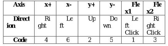
V. EXPERIMENTAL RESULTS
The test results were listed for users in both groups of keyboard and music, as shown in Table I and Table II.
Axis x+ x- y+ y- Fle
x1 Fle x2 Direct ion Ri ght Le ft
Up Do wn Le ft Click Ri ght Click
Code 4 6 2 5 1 3
Table 1: The Test Results Of The New Hand Computer Mouse Interface
Comma nds
Play Next Back Stop
Code 2 3 4 5
Table 2: The Test Result of The Music System
VI.CONCLUSION
This paper deals with the hand-controlled mouse relies on infrared and ultrasonic signals, the transmitter placed on the hand sends signals to the remote receiver after a motion is detected. However, the user must focus on the cursor’s movement on the computer screen and assure that the transmitted signals are within the reception range of the receiver. Specifically, for people with disabilities to overcome inconveniences in their daily lives, we have utilized the least amount of circuitry as well as highly accurate control system to generate devices. The system presented in this paper allows people with disabilities to avoid the need to use uncomfortable input methods such as clutching a mouth stick. Rather, this system employs a tilt sensor module to control the computer mouse in response to the movements of hand’s rotation.
REFERENCES
1. E. Peizer, E. J. Lorenze, and M. Dixon, “Environmental controls to promote independence in severly disabled elderly persons,” Med. Instrument., vol. 16, no. 3, pp. 171 –173, May–June 1982.
2. J. J. Vasa, “Electronic aids for the disabled and the elderly,” Med. Instrument., vol. 16, no. 5, pp. 263–264, Sept.–Oct. 1982.
3. Y. L. Chen, F. T. Tang, W. H. Chang, M. K. Wong, Y.Y. Shih, and T. S.Kuo, “The new design of an infrared-controlled human–computer interface for the disabled,” IEEE Trans. Rehab. Eng., vol. 7, pp. 474–481,Dec. 1999.
4. Yu-Luen Chen” Application of Tilt Sensors in Human–Computer Mouse Interface for People With Disabilities” IEEE transactions on Neural systems and Rehabilitation engineering, vol. 9, no. 3, september 2001
5. Md.R.Ahsan, Muhammad I.Ibrahimy, Othman O.Khalifa “EMG Signal Classification for Human Computer Interaction:A Review” European journal of scientific Research ISSN 1450-216X vol33 n0.3 (2009), pp.480-501
6. Jose Sellek,Wunnava Subbarao, Hussein Khorram” Non Invasive Bio Sensing for Eye Blinking and Head movement” IEEE Engineering in Medicine & Biology Society 10th annual international conference--0801 ch2566-8/88/0000—0801
7. K. Y. Tsai and J. H. Chang, “The development an eye-movement controlled man–machine interface for disable: Optical eye-mouse,”in Proc. Biomedical Engineering Society 1997 Annu. Symp., Taipei,Taiwan, R.O.C., Dec. 1997, pp. 434–444.
8. W. J. Perkins and B. F. Stenning, “Control units for operation of computers by severely physical handicapped persons,” J. Med. Eng.Technol., vol. 10, no. 1, pp. 21 –23, Jan.–Feb. 1986.
9. H. S. Ranu, “Engineering aspects of rehabilitation for the handicapped,” J. Med. Eng. Technol., vol. 10, no. 1, pp. 16–20, Jan.–Feb. 1986. 10. B.Andrews, S. Miller, D. Horrocks, J. O. N. Jibowu, J. C. Chawla, and F. R. C. S. , “Electronic communications and environmental control
systems for the severely disabled,” Paraplegia, vol. 17, pp. 153–156, 1980.
11. M. J. Kilgallon, D. P. Roberts, and S. Miller, “Adapting personal computers for use by high-level quadripegics,” Med. Instrument., vol. 21, no.2, pp. 97–102, 1987.
12. N. Gravil, P. A. Griffiths, R. Potter, and A. Yates, “Eye control of microcomputer,”Comput. Bull. Serial, vol. 3, pp. 15–16, 1985.
13. Z. A. Keirn and J. I. Aunon, “Alternative modes of communication between man and his surroundings,” IEEE Trans Biomed. Eng., to be published.
ISSN(Online): 2320-9801
ISSN (Print): 2320-9798
I
nternational
J
ournal of
I
nnovative
R
esearch in
C
omputer
and
C
ommunication
E
ngineering
(An ISO 3297: 2007 Certified Organization)
Vol. 4, Issue 8, August 2016
15. J. R. Lacourse and F. C. Hladik, Jr., “An eye movement communication control system for the disabled,” IEEE Trans. Biomed.Eng., vol. 37, pp.1215–1220, Dec. 1990.
16. D. Asche, A. Cook, and H. Van Ness, “A three-electrode EOG for use as a communication interface for the nonvocal, physically handicapped,” in Proc. Annu. Conf. Engineering Medicine Biology, vol. 18, New York,Oct. 1976, p. 2
17. G. A. Rinard, R. W. Matteson, R. W. Quine, and R. S. Tegtmeyer, “An infrared system for determining ocular position,” ISA Trans., vol. 19, no.4, pp. 3–6, 1980.
18. R. D. Richard, B. Stein, B. J. Andrews, K. B. James, and M. Wieler, “Application of tilt sensors in functional electrical stimulation,” IEEE Trans. Rehab. Eng., vol. 4, pp. 63–71, Mar. 1996.
19. E. O. Otun and A. D. Anderson, “An inclinometric method for continuous measurment of sagittal movement of the lumbar spine,” Ergonomics, vol. 31, pp. 305–315, 1988.
20. B. J. Andrews, R. H. Baxendale, R. Barnett, G. F. Phillips, J. P. Paul, and P. A. Freeman, “A hybrid orthosis for paraplegics incorporating feedback control,” in Proc. 9th Int. Symp. Advances Control Human Extremities, Dublin, Ireland, July 1987, pp. 297–311.
21. P. Bowker and G. H. Heath, “Control of peroneal functional electrical stimulation using a magneto transducer to monitor angular velocity of the knee,” in Proc. World Cong. Int. Soc. Prosthesis Orthopaedics, Melbourne, Australia, June 1995, p. 61.
22. Hamed H. SAD, Franck Poirier"Evaluation and modeling of user performance for pointing and scrolling tasks on handheld devices using tilt sensor" 2009 Second International Conferences on Advances in Computer-Hu man Interactions.
BIOGRAPHY
A. Shivani J. Pawar, student of M.E (E&TC) 2nd Year CSMSS Engineering College, Aurangabad,
Maharashtra, India. B.E (E.C) from Deogiri College of Engineering & Management, Aurangabad, Maharashtra in 2013.
Prof. A.M Rawate