ISSN(Online): 2320-9801
ISSN (Print): 2320-9798
I
nternational
J
ournal of
I
nnovative
R
esearch in
C
omputer
and
C
ommunication
E
ngineering
(An ISO 3297: 2007 Certified Organization)
Vol. 4, Issue 9, September 2016
Improving Quality of Image Using PCA and
DSWT at Two Level Decomposition
Nishu Rani, Er. Rachna Rajput
M.Tech Student, Dept. of CSE, Guru Kashi University, Talwandi Sabo, India
Assistant Professor, Dept. of CSE, Guru Kashi University, Talwandi Sabo, India
ABSTRACT: The fast development of digital image processing leads to the growth of feature extraction of images which leads to the development of Image fusion. The process of combining two different images into a new single image by retaining salient features from each image with extended information content is known as Image fusion. Two approaches to image fusion are Spatial Fusion and Transform fusion. Discrete Wavelet Transform plays a vital role in image fusion since it minimizes structural distortions among the various other transforms. Lack of shift invariance, poor directional selectivity and the absence of phase information are the drawbacks of Discrete Wavelet Transform. These drawbacks are overcome by Stationary Wavelet Transform and Dual Tree Complex Wavelet Transform and Principal Component Analysis (PCA). An image resolution enhancement technique based on interpolation of the high frequency subband images obtained by discrete wavelet transform (DWT), SWT, PCA and the input image. The edges are enhanced by introducing an intermediate stage by using stationary wavelet transform (SWT). DWT is applied in order to decompose an input image into different subbands. PCA maintains the high frequency subbands as well as the input image are interpolated. The estimated high frequency subbands are being modified by using high frequency subband obtained through SWT and DWT. Then all these subbands are combined to generate a new high resolution image by using inverse DWT (IDWT), inverse SWT and inverse of PCA. The quantitative and visual results are showing the superiority of the proposed technique over the conventional and state-of-art image resolution enhancement techniques HE and denoising using MDBUTMF filter. Parameters are also used to measure value such as PSNR, MSE, Normalized Correlation, CoC and Elapsed Time. Our proposed technique PCA with DSWT results better quality of visualization
KEYWORDS: Energy DWT, MDBUTMF, IDWT, SWT, Transform Fusion, PCA.
I. INTRODUCTION
ISSN(Online): 2320-9801
ISSN (Print): 2320-9798
I
nternational
J
ournal of
I
nnovative
R
esearch in
C
omputer
and
C
ommunication
E
ngineering
(An ISO 3297: 2007 Certified Organization)
Vol. 4, Issue 9, September 2016
have been proposed for the purpose of image denoising, the problem of image noise suppression remains an open challenge, especially in situations where the images are acquired under poor conditions where the noise level is very high.
Image denoising problem is still a bottleneck for the researchers because removal of noise causes the artifacts and image blurring. Different methodologies for noise reduction are given to us that insights into the methods to determine which method will provide the reliable and approximate estimate of original image given its degraded version.
Image de-noising done by filtering. Filtering is divided in broad categories. De-noising of images in medical science is still a challenging problem. There have so many techniques and algorithms published. Each has their own assumptions, limitations and advantages. Methods of image de-noising are spatial domain and transform domain. Linear filter such as Weiner, non-linear threshold filtering, wavelet coefficient model, non-orthogonal wavelet transform, wavelet shrinkage, anisotropic filtering, trilateral filtering etc. example of spatial filtering are Mean filtering and Gaussian filtering. Linear filters result is not better because they destroy the fine details and lines and also blur the sharp edges. Bilateral filter recently used for de-noise the images. Its work effectively with high frequency areas but it fails to work at low frequency; it fails to remove salt and pepper noise and gives low performance to remove speckle noise. So each technique or filter or algorithm has its own advantages and limitations and drawbacks. So still there are so many filters for images de-noising.
II. RELATED WORK
ISSN(Online): 2320-9801
ISSN (Print): 2320-9798
I
nternational
J
ournal of
I
nnovative
R
esearch in
C
omputer
and
C
ommunication
E
ngineering
(An ISO 3297: 2007 Certified Organization)
Vol. 4, Issue 9, September 2016
ISSN(Online): 2320-9801
ISSN (Print): 2320-9798
I
nternational
J
ournal of
I
nnovative
R
esearch in
C
omputer
and
C
ommunication
E
ngineering
(An ISO 3297: 2007 Certified Organization)
Vol. 4, Issue 9, September 2016
III.PROPOSEDALGORITHM
Figure 1.1: Flow chart for enhancement of denoising fused image
IV.RESULTSECTION
The GUI part is designed for Enhancement with denoised fused image working with various fusion techniques such as
PCA, DWT-1st level, SWT-1st Level, DWT-2nd Level, SWT-2nd Level, DSWT-2nd Level and Proposed (2-DSWT +
PCA) technique. We used to run the main program by clicking on the gui.m file in Matlab. As we have implemented our work in Matlab to enhance the fused denoised images.
Figure 1.2: GUI Window for selecting various fusion techniques for enhancing denoised fused image.
Above figure state that we can select various fusion techniques such as PCA, DWT-1st level, SWT-1st Level, DWT-2nd
Level, SWT-2nd Level, DSWT-2nd Level and Proposed (2-DSWT + PCA) technique on clicking button which you want
ISSN(Online): 2320-9801
ISSN (Print): 2320-9798
I
nternational
J
ournal of
I
nnovative
R
esearch in
C
omputer
and
C
ommunication
E
ngineering
(An ISO 3297: 2007 Certified Organization)
Vol. 4, Issue 9, September 2016
For below two browsing window figure 1.3 and 1.4 are common used for all fusion technique as above stated.
Figure 1.3: Browsing window for selecting first image.
Figure 1.3, above shows the browsing window for selecting the first image as for various fusion techniques. Any color image is selected. First and second image both which we are browsing should of same size and of same pixels for fusion.
Figure 1.4: Browsing window for selecting Second image.
Figure 1.4, above shows the browsing window for selecting the Second image as for all fusion techniques. Second image which we are selecting should be of previous size and pixel image.
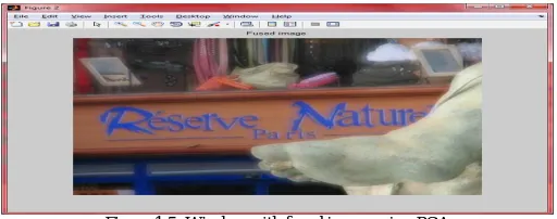
A. PCA TECHNIQUE RESULT
Below mentioned figure shows the result of PCA technique.
Figure 1.5: Window with fused image using PCA
ISSN(Online): 2320-9801
ISSN (Print): 2320-9798
I
nternational
J
ournal of
I
nnovative
R
esearch in
C
omputer
and
C
ommunication
E
ngineering
(An ISO 3297: 2007 Certified Organization)
Vol. 4, Issue 9, September 2016
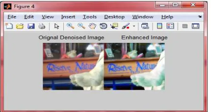
Figure 1.6: Window with Denoised fused image and Enhanced image using PCA
Figure 1.6, shows the denoised fused image and Enhanced image using PCA fusion technique. In this, PCA fused image is selected and MDBUTMF is used for denoising or removing the unwanted noise from this fused PCA image and results in Denoised Fused image. This Denoised image is selected on which Histogram Equalization technique for enhancing is applied getting better quality image.
B. DWT-1ST LEVEL TECHNIQUE RESULT
Below mentioned figure shows the result of DWT-1st Level technique.
Figure 1.7: Window with fused image using DWT-1st Level
Figure 1.7, shows the fused image which we have browsed in figure 1.3 and 1.4 as first and second image respectively.
The fused image after using DWT-1st Level fusion technique.
Figure 1.8: Window with Denoised fused image and Enhanced image using DWT-1st Level
Figure 1.8, shows the denoised fused image and Enhanced Image respectively using DWT-1st Level fusion technique.
In this, DWT-1st Level fused image is selected and MDBUTMF is used for denoising or removing the unwanted noise
from this fused DWT-1st Level image and results in Denoised Fused image. This Denoised image is selected on which
ISSN(Online): 2320-9801
ISSN (Print): 2320-9798
I
nternational
J
ournal of
I
nnovative
R
esearch in
C
omputer
and
C
ommunication
E
ngineering
(An ISO 3297: 2007 Certified Organization)
Vol. 4, Issue 9, September 2016
C. SWT-1ST LEVEL TECHNIQUE RESULT
Below mentioned figure shows the result of SWT-1st Level technique.
Figure 1.9: Window with fused image using SWT-1st Level
Figure 1.9, shows the fused image which we have browsed in figure 1.3 and 1.4 as first and second image respectively.
The fused image after using SWT-1st Level fusion technique.
Figure 1.10: Window with Denoised fused image and Enhanced image using SWT-1st Level
Figure 1.10, shows the denoised fused image and Enhanced Image respectively using SWT-1st Level fusion technique.
In this, SWT-1st Level fused image is selected and MDBUTMF is used for denoising or removing the unwanted noise
from this fused SWT-1st Level image and results in Denoised Fused image. This Denoised image is selected on which
Histogram Equalization technique for enhancing is applied getting better quality image.
D. DWT-2ND LEVEL TECHNIQUE RESULT
Below mentioned figure shows the result of DWT-2nd Level technique.
Figure 1.11: Window with fused image using DWT-2nd Level
Figure 1.11, shows the fused image which we have browsed in figure 1.3 and 1.4 as first and second image
ISSN(Online): 2320-9801
ISSN (Print): 2320-9798
I
nternational
J
ournal of
I
nnovative
R
esearch in
C
omputer
and
C
ommunication
E
ngineering
(An ISO 3297: 2007 Certified Organization)
Vol. 4, Issue 9, September 2016
Figure 1.12: Window with Denoised fused image and Enhanced image using DWT-2nd Level
Figure 1.12, shows the denoised fused image and Enhanced Image respectively using DWT-2nd Level fusion technique.
In this, DWT-2nd Level fused image is selected and MDBUTMF is used for denoising or removing the unwanted noise
from this fused DWT-2nd Level image and results in Denoised Fused image. This Denoised image is selected on which
Histogram Equalization technique for enhancing is applied getting better quality image.
E. SWT-2ND LEVEL TECHNIQUE RESULT
Below mentioned figure shows the result of SWT-2nd Level technique.
Figure 1.13: Window with fused image using SWT-2nd Level
Figure 1.13, shows the fused image which we have browsed in figure 1.3 and 1.4 as first and second image
respectively. The fused image after using SWT-2nd Level fusion technique.
Figure 1.14: Window with Denoised fused image and Enhanced image using SWT-2nd Level
Figure 1.14, shows the denoised fused image and Enhanced Image respectively using SWT-2nd Level fusion technique.
In this, SWT-2nd Level fused image is selected and MDBUTMF is used for denoising or removing the unwanted noise
from this fused SWT-2nd Level image and results in Denoised Fused image. This Denoised image is selected on which
ISSN(Online): 2320-9801
ISSN (Print): 2320-9798
I
nternational
J
ournal of
I
nnovative
R
esearch in
C
omputer
and
C
ommunication
E
ngineering
(An ISO 3297: 2007 Certified Organization)
Vol. 4, Issue 9, September 2016
F. DSWT-2ND LEVEL TECHNIQUE RESULT
Below mentioned figure shows the result of DSWT-2nd Level technique.
Figure 1.15: Window with fused image using DSWT-2nd Level
Figure 1.15, shows the fused image which we have browsed in figure 1.3 and 1.4 as first and second image
respectively. The fused image after using DSWT-2nd Level fusion technique.
Figure 1.16: Window with Denoised fused image and Enhanced image using DSWT-2nd Level
Figure 1.16, shows the denoised fused image and Enhanced Image respectively using DSWT-2nd Level fusion
technique. In this, DSWT-2nd Level fused image is selected and MDBUTMF is used for denoising or removing the
unwanted noise from this fused DSWT-2nd Level image and results in Denoised Fused image. This Denoised image is
selected on which Histogram Equalization technique for enhancing is applied getting better quality image.
G. PCA + DSWT-2ND LEVEL TECHNIQUE RESULT
Below mentioned figure shows the result of PCA+DSWT-2nd Level technique.
Figure 1.17: Window with fused image using PCA+DSWT-2nd Level
Figure 1.17, shows the fused image which we have browsed in figure 1.3 and 1.4 as first and second image
ISSN(Online): 2320-9801
ISSN (Print): 2320-9798
I
nternational
J
ournal of
I
nnovative
R
esearch in
C
omputer
and
C
ommunication
E
ngineering
(An ISO 3297: 2007 Certified Organization)
Vol. 4, Issue 9, September 2016
Figure 1.18, shows the denoised fused image and Enhanced Image respectively using PCA+DSWT-2nd Level fusion
technique. In this, PCA+DSWT-2nd Level fused image is selected and MDBUTMF is used for denoising or removing
the unwanted noise from this fused PCA+DSWT-2nd Level image and results in Denoised Fused image. This Denoised
image is selected on which Histogram Equalization technique for enhancing is applied getting better quality image.
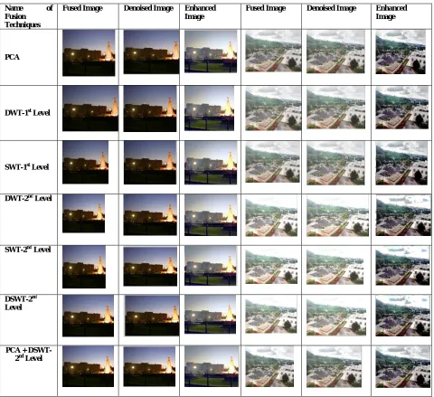
V. RESULTSANDDISCUSSION
Below figure 1.19 shows the images on which test is performed as input and output comes. Figure 1.19 shows the fused images with denoised and enhanced images with various working of fusion techniques and hybriding them.
Name of
Fusion Techniques
Fused Image Denoised Image Enhanced
Image
Fused Image Denoised Image Enhanced
Image
PCA
DWT-1st Level
SWT-1st Level
DWT-2nd Level
SWT-2nd Level
DSWT-2nd Level
PCA + DSWT-2nd Level
ISSN(Online): 2320-9801
ISSN (Print): 2320-9798
I
nternational
J
ournal of
I
nnovative
R
esearch in
C
omputer
and
C
ommunication
E
ngineering
(An ISO 3297: 2007 Certified Organization)
Vol. 4, Issue 9, September 2016
Table 1.1: PSNR, MSE , NK, Elapsed Time and CoC as parameters for Fused and Denoised Enhanced image
Technique/Images Name
Temple Buliding
PSNR MSE NK CoC Elapsed Time
PSNR MSE NK CoC Elapsed Time
PCA 60.9737 0.05218 1.48657 0.971 1.521 64.930 0.02137 0.85022 0.9932 1.431
DWT-1st Level 59.5946 0.07153 1.67935 0.965 2.582 63.584 0.02901 0.81950 0.9940 1.910
SWT-1st Level 59.5882 0.07168 1.68031 0.964 3.788 63.579 0.02906 0.81931 0.9938 2.412
DWT-2nd Level 61.4383 0.04693 1.418 0.969 2.587 59.950 0.06642 0.74186 0.9594 2.419
SWT-2nd Level 61.4354 0.04698 1.41869 0.969 4.994 59.882 0.06754 0.74669 0.9585 3.133
DSWT-2nd Level 61.4485 0.04681 1.41907 0.969 4.080 59.899 0.06726 0.74248 0.9593 3.076
PCA+DSWT-2nd
Level
62.6796 0.03553 1.30635 0.974 4.525 65.115 0.02044 0.83764 0.9946 3.438
Above figures and table shows the result of enhanced denoised fused image using various fusion techniques and with
new hybrid approach. İmages are tested on different parameters to get best results. PCA+ DSWT 2nd Level fusion technique which is proposed technique has been resulted best in quality among the parameters such as PSNR, MSE and Coc in some extended images. NK of the images is in range is maintained in our proposed techniques. Next to our proposed algorithm is DWT 2nd level or sometimes SWT at 2nd level. PSNR should be high in quality. MSE is difference in both image, so low should be there. NK stands for Normalized Correlation means Similarity of two images or signals should be maintained. Coc stands for Correlation of Coefficient means pixel quality of images are compared. Elapsed time is the total time taken by each technique to solve the problem.
VI.CONCLUSIONANDFUTUREWORK
This work proposed an image resolution enhancement technique based on the interpolation of the high frequency subbands obtained by PCA + DSWT 2nd Level, correcting the high frequency subband estimation by using SWT high frequency subbands, and the input image firstly by DWT 2nd level after that PCA is applied on these images. The proposed technique uses SWT, DWT and PCA to decompose an image into different subbands, and then the high frequency subband images have been interpolated. The interpolated high frequency subband coefficients have been corrected by using the high frequency subbands achieved by SWT, DWT and PCA of the input image. Afterwards all these images have been combined using IDWT and Inverse of PCA to generate a super resolved imaged. An original fused image is denoising using MDBUTMF filter. Enhancement is done by Spatial filtering technique known as Histogram Equalization. Results can be measured by parameters such as PSNR, MSE, Normalized Correlation, CoC and Elapsed Time. We have not done any comparison but just hybrid the SWT, DWT and PCA 2nd Level fusion technique as to enhance the color images after denoising also as to preserve brightness more which results in better visualization.
ISSN(Online): 2320-9801
ISSN (Print): 2320-9798
I
nternational
J
ournal of
I
nnovative
R
esearch in
C
omputer
and
C
ommunication
E
ngineering
(An ISO 3297: 2007 Certified Organization)
Vol. 4, Issue 9, September 2016
REFERENCES
[1]. Ashishgoud Purushotham G. Usha Rani Samiha Naik, “Image Fusion Using DWT & PCA”, International Journal of Advanced Research in Computer Science and Software Engineering, Volume 5, Issue 4, 2015.
[2]. B Siva Kumar,” Discrete and Stationary Wavelet Decomposition for IMAGE Resolution Enhancement”, International Journal of Engineering Trends and Technology (IJETT) - Volume4 Issue7- July 2013.
[3]. G.Amar Tej , Prashanth.K.Shah, “Efficient quality analysis and enhancement of MRI image using Filters and Wavelets”, International Journal of Advanced Research in Computer and Communication Engineering, Vol. 4, Issue 6, June 2015.
[4]. Haweezet et al,” SVD-DWT Based Digital Video Watermarking Using Fused Images and Low-Middle Frequency Bands”, International Journal of Advanced Research in Computer Science and Software Engineering Volume 4, Issue 8, August 2014.
[5]. Kanagaraj Kannan et al.,” Optimal Decomposition Level of Discrete, Stationary and Dual Tree Complex Wavelet Transform for Pixel based Fusion of Multi-focused Images”, SERBIAN JOURNAL OF ELECTRICAL ENGINEERING Vol. 7, No. 1, May 2010, 81-93.
[6]. K. S. Jeen Marseline et al,” A Study on the Application Of Wavelet Transformation to Preprocess Sonar Images Through Noise Removal”, International Journal of Scientific and Research Publications, Volume 3, Issue 2, February 2013 1 ISSN 2250-3153.
[7]. Mirajkar Pradnya P,” IMAGE FUSION BASED ON STATIONARY WAVELET TRANSFORM”, International Journal of Advanced Engineering Research and Studies, II/ IV/July-Sept., 2013/99-101.
[8]. Pravin R. Dabhi, Prof. S G.Bari,” Resolution Enhancement of High Noise Satellite Images Using DT-DWT Based Fusion Algorithm”, JETIR, Volume 2, Issue 4, ISSN-2349-5162, April 2015.
[9]. K.Prasad, B. Jayanth nadh, B.Hymavathi,“High Density Salt and Pepper Noise Removal in color and grayscale images Through Modified DBUTMF”, International Journal of Advanced Research in Computer Engineering & Technology (IJARCET),Volume 1, Issue 7, September 2012 [10]. Jigar R. Patel, Jwolin M. Patel, “Medical Image Fusion Technique Using Single level and Multilevel DWT” International Journal of Engineering Research & Technology (IJERT) Vol. 3 Issue 1, ISSN: 2278-0181, January – 2014.
[11]. Rajenda Pandit Desale and Sarita V. Verma, “Study and Analysis of PCA, DCT & DWT based Image Fusion Techniques” IEEE International Conference on Signal Processing, Image Processing and Pattern Recognition, 2013.
[12]. S. A. Quadri And Othman Sidek, “Pixel-Level Image Fusion using Kalman Algorithm” International Journal of Signal Processing, Image Processing And Pattern Recognition Vol. 6, No. 2, April, 2013.
[13]. Rohan Ashok Mandhare1, Pragati Upadhyay2, Sudha Gupta, “Pixel-Level Image Fusion Using Brovey Transforme And Wavelet Transform” International Journal Of Advanced Research In Electrical, Electronics And Instrumentation Engineering Vol. 2, Issue 6, June 2013.
[14]. Somkuwar R. Sandeep,” A Review Paper on: Various Contrast Enrichment Techniques and Their Improved Factors”, International Journal of Advanced Research in Computer Science and Software Engineering, Volume 3, Issue 9 , pp:356-361.
[15]. Sonker Dinesh,” Comparison of Histogram Equalization Techniques for Image Enhancement of Grayscale images of Dawn and Dusk”, International Journal of Modern Engineering Research (IJMER), Vol. 3, Issue. 4, Jul - Aug. 2013 pp-2476-2480.
[16]. Abubakar1 Muhammad Fari,” Image Enhancement using Histogram Equalization and Spatial Filtering”, International Journal of Science and Research (IJSR), Volume 1 Issue 3, pp: 15-20.