Double Mode Automatic Wireless Railway
Gate Control System Using Android App
M.B.Jhansi Lakshmi1, A.V.Krishna2, N.Pruthvi Raj3, M.Bhargav Sai4, K.Kavya Chowdary5
B.Tech, Dept. of E.C.E, D.M.S.S.V.H College of Engineering, Machilipatnam, India1345
Asst. Professor, Dept. of E.C.E, D.M.S.S.V.H College of Engineering, Machilipatnam, India2
ABSTRACT: This paper describes the automatic railway tracking and gate control system using android app and WI-FI module for saving human lives and avoiding major disasters in railway track. Railway gate may be saved for the road users to prevent accidents in terms of train speed at level crossing. The system can operate in two modes. One mode is for unmanned railway gate and the other for manned gates. In manned gate control mode, the system receives the input signal from the android phone and sends information to the gate motor driver for opening and closing the gate. The gate is closed, when the train enters in the specified range and the gate is opened. In the unmanned gate control gate, the system receives input from the vibration sensors placed under the track. Usually the vibrations sensors will detect automatically close the gate until vibrations cease to exist with a safety time window.
KEYWORDS: Major disasters, android mobile, unmanned rail gate, vibrations
I. INTRODUCTION
At the level crossing between the railroad and highway there are many railway accidents happening. To prevent this type of railway accidents and to reduce man power we use an android app and WIFI module in railway gate control system
In everywhere at level crossing between railroad and highway there are many railway accidents happening due to the laziness and carelessness in manual operations or lack of workers. This system uses
MSP430 microcontroller as the main component. MSP430 microcontroller is the heart of our system. Android app is mainly designed for sending the Wireless signal to the WI-FI module. The android app has two buttons open to open the gate and close to close the gate.
II. RELATED WORK
Fig 1: The system for Automatic wireless railway gate control
III. MSP430 MICROCONTROLLER
MSP is the mixed-signal low power Microcontroller. MSP430 is specifically designed for Ultra-Low-Power applications. Its flexible clocking system, multiple low power modes enable ultra low power optimization. The MSP430 CPU has RISC architecture.
Features of MSP430 microcontroller are : Ultra low power architecture , Low power consumption, Low operating voltage (from 1.8V to 3.6V), Large register files, Prioritized and nested inputs
Flash options : 512 KB
RAM options : 66 KB
ROM options : 16 KB
ADC options : 12-bit SAR
GPIO options : 74 pins
Other integrated peripherals: USB, LCD, DAC, Comparator, DMA, 32x32 multiplier, power management module, watchdog timer, Real Time Clock, Temperature sensor
IV. ENERGIA SOFTWARE
Energia is an open source and community driven integrated development environment and software framework. Energia provides an intuitive coding environment as well as asturdy framework of easy-to-use functional Application Programming Interfaces & libraries for programming a microcontroller.
Features of Energia :
Simple & easy-to-use code editor & compiler with built-in Serial Monitor/terminal. Features a robust framework of intuitive functional APIs for controlling microcontroller peripherals (i.e. Digital Read, digital Write, Serial. Print, etc). Higher level libraries are also available (i.e. Wi-Fi, Ethernet, displays, sensors & more)
V. ESP8266 WI-FI MODULE
ESP8266 WIFI module is a microcontroller unit with integrated TCP/IP protocol stack that can give any microcontroller access to your WIFI network. This module has on-board processing and storage capability that allows it to be integrated withsensors and other specific devices through GPIOs
The CPU of ESP8266 runs at 160MHz. Flash : 40MHz – 80MHz Temperature range : -40 C to 125 C
ESP8266 has 8 pins, 4 pins are arranged in 2 rows. The first pin on the top left is GND. The two pins right from the Ground are GPIO 2 and 0. The pin on the top right side is the RX pin and the lower pin on the left side is Transmitter pin. These are the pins for communication. The middle pins at the bottom are Chip Power-Down(CH_PD) and RST(reset).
WIFI direct (p2p). Integrated TCP/IP protocol stack. Integrated power amplifier and matching network. 1MB flash memory
Flash Memory : This memory can be both programmed and erased electrically. Power down leakage current of <10 micro amps.
Integrated low power 32-bit CPU. Wake up and transmit packets in < 2 milli seconds. Stand by power consumption of <1.0 milli watts. 64Kb instruction RAM. 96Kb data RAM
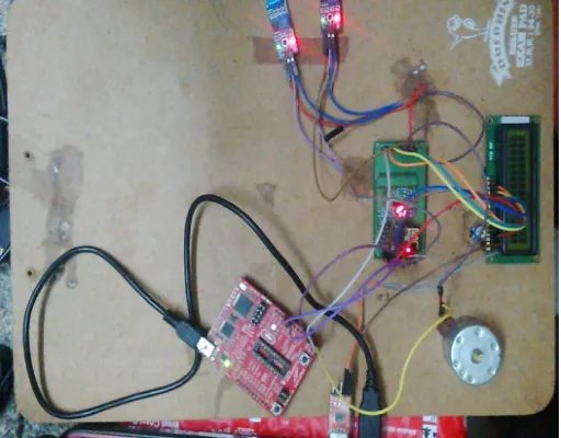
Fig 2 : prototype of overall system
VI. FLOW CHART
VII. MODULES OF RAILWAY CONTROL SYSTEM
a. VIBRATION SENSOR :
Vibration sensors are those sensors used for measuring the vibrations occurring from the devices displaying, and analyzing linear velocity, displacement and proximity, or acceleration. It has 3 pins vcc, ground and data. Vibration sensors are the sensing elements that detect the vibration of the train coming or passing by. The system receives the input from the vibration sensors that are placed under the track. Usually the vibrations coming from the train persistent for seconds which the system will detect and automatically close the gate. The output of the vibration sensor is analog in nature.
Here the mode select circuit is used to switch from manned mode to the unmanned mode and vice-versa. c. ANDROID MOBILE :
The android mobile has the android app which sends the message to the WIFI module. The android app has two options open and close. When we choose open/close the WIFI module receives the signal and gives as input to the microcontroller and the gate automatically opened/closed.
VIII. RESULT AND ANALYSIS
d. TRAIN DEPARTED :
Fig3: open gate mode
When the train crosses the gate and reaches the second vibration sensor then it will be displayed on the character LCD that the train has departed and the gate is opening
e. TRAIN ARRIVED :
Fig4: closed gate mode
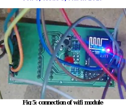
Fig 5: connection of wifi module
The wifi module creates a server with an IP address for a client to be connected. The blue LED indicates that the android mobile is connected to the WI-FI module. It also indicates that the module is receiving message from android mobile.
IX. CONCLUSION
Finally we conclude that our project is designed to prevent the railway accidents and to reduce the man power. By using android app and Wi-Fi module we can find current longitude and latitude position of train in caves and high altitude without restriction of distance. This system improves reliability of communication up to great extent and it is low cost system. By using DC motor gate can operated automatically.
X. ACKNOWLGEMENT
We are acknowledge our indebtedness and convey our sincere thanks to our Project Guide MR.A V KRISHNA, faculty of ECE DEPT,DMS SVH COLLEGE, MACHILIPATNAM. Who sincerely helped us to giving inspiration, new ideas and infrastructure throughout the semester. We would also like to thanks ECE department of , to give us such platform for making this project successfully. We also convey our thanks to the faculty of our college & our group member who have helped entirely. At last, we again convey our special thanks to project guide, who decided to shows the model of the project at the workshop arranged at the time.
REFERCENCES
1. Krishna, Shashi Yadav and Nidhi, “Automatic Railway Gate Control Using Microcontroller”, Oriental Journal Of Computer Science &
Technology, Vol.6, No.4, December 2008.
2. J.Banuchandar, V. Kaliraj, P. Balasubramanian, S. Deepa, N. Thamilarasi,“ Automated Unmanned Railway Level Crossing System”, in
International Journal of Modern Engineering Research (IJMER) Volume.2, Issue.1, Jan-Feb 2012 pp-458463.
3. Kalpana Sharma, J. Kumawat, S. Maheshwai, Neeti Jain “Railway Security System based on Wireless Sensor Networks: State of the Art
“InIntenational Journal of Computer Application (0975-8887) volume 96-no. 25, June 2010.
4. Ahmed Salih Mahdi. Al-Zuhairi,“Automatic Railway Gate and Crossing Control based Sensors &Microcontroller ”, IN International Journal of
Computer Trends and Technology (IJCTT) – Volume 4 Issue 7–July 2013
5. G. Bhatia, A. Lala, A. Chaurasia: “Implementation of Cloud Computing Technology in Indian Railway System.” In International Conference of
Network Technology (ICINT 2012), IACSIT Press, Singapore.
6. A. Kottalil, A. Ajamal, A. Babu: “Automatic Railway Gate Control System” Oriental Journal of Computer Science & Technology, Vol.6, No.4,
February 2014
9. Mansingh, B.Brailson; Selvakumar, K.S.; Kumar, S.R.Vignesh, "Automation in unmanned railway level crossing," in Intelligent Systems and Control (ISCO), 2015 IEEE 9th International Conference on ,vol.,no.,pp.1-4,9-10Jan.2015.
10. K. Vidyasagar, P. SekharBabu, R. RamPrasad “Anti Collision and Secured Level Crossing System”, International Journal of Computer
Applications(0975 – 8887) Volume 107 – No 3, December 2014”.
11. Priyanka.J, C.Saranya, A.Shanmathi, C. Baranikumar, S., "Automatic level crossing gate with database collection," in Computation of Power,
Energy Information and Communication (ICCPEIC), 2015 International Conference on , vol., no., pp.0388- 0392,22-23April2015.
12. Bernard Cole, “ Real-time Android: real possibility, really hard to do - or just plain impossible?” Embedded.com May 13,2012
BIOGRAPHY
M.B.Jhansi Lakshmi pursuing B.tech in Electronics and Communication Department in the D.M.S.S.V.H college of engineering affliated to JNTUK university, Machilipatnam, Andhra Pradesh, India
A.Venkata Krishna working as Assistant Professor in the department of Electronics and Communication in D.M.S.S.V.H college of engineering affliated to JNTUK university, Machilipatnam, Andhra Pradesh, India
N.Pruthvi Raj pursuing B.tech in Electronics and Communication Department in the D.M.S.S.V.H college of engineering affliated to JNTUK university, Machilipatnam, Andhra Pradesh, India
M.Bhargav Sai pursuing B.tech in Electronics and Communication Department in the D.M.S.S.V.H college of engineering affliated to JNTUK university, Machilipatnam, Andhra Pradesh, India