Hardware Implementation of Image
Compression Using Lifting Scheme Based On
DWT Techniques
Shaik Haseena Begam1, P.Bala Murali Krishna2
PG Student, Dept. of ECE, Sri Mittapalli Institute of Technology for Women, Tummalapalem, Guntur, A.P, India1
Professor, Dept. of ECE, Sri Mittapalli Institute of Technology for Women, Tummalapalem, Guntur, A.P, India2
ABSTRACT: This paper proposes the design of VLSI architecture for image compression. To perform the process of image compression, VLSI architecture is designed using lifting-based discrete wavelet transform (DWT) and it is implemented in Spartan 3EDK kit. The lifting-based DWT architecture has the advantage of lower computational complexity and higher efficiency. Through the DWT, signals can be decomposed into different sub bands with both time and frequency information. Traditional DWT architectures are based on convolution. The second-generation DWTs, which are based on lifting algorithms, are proposed. Compared with convolution-based, lifting-based architectures are not only having lower computation complexity but also require less memory. Here we proved the image compression by using Micro-blaze core processor with the help of XILINX platform studio Design suite. The algorithm is written in system C Language and tested in SPARTAN-3 FPGA kit by interfacing a test circuit with the PC using the RS232 cable. In this proposed system, the core processor Micro-blaze is converted into a lifting based DWT architecture. The test results are seen to be satisfactory.
KEYWORDS: 1D-DWT, 2D-DWT, Micro-blaze, EDK Tool, Lifting method.
I. INTRODUCTION
The wavelet transformation is a widely used technique for image processing applications. Unlike traditional transforms such as the Fast Fourier Transform (FFT) and Discrete Cosine Transform (DCT), the Discrete Wavelet Transform (DWT) holds both in time and frequency information, based on a multi-resolution analysis framework. Digital image processing is the use of computer algorithms to perform image processing on digital images. As a subcategory or field of digital signal processing, digital image processing has many advantages over analog image processing. It allows a much wider range of algorithms to be applied to the input data and can avoid problems such as the build-up of noise and signal distortion during processing.
The Field programmable gate array (FPGA) implementation of DWT results in higher processing speed and lower costs when compared to other implementations such as PCs, ARM processors, DSPS etc. The discrete wavelet transform is therefore increasingly used for image coding [1-4]. This is because the DWT can decompose the signals into different sub-bands with in time and frequency information and facilitate to arrival high compression ratio [11].
The advantage of DWT over various ancient transformations is that it performs multi resolution analysis of signals with localization each in time and frequency. The DWT is being progressively used for compression these days since it supports choices like progressive image transmission (by quality, by resolution), simple compressed image manipulation, region of interest writing, etc. The JPEG 2000 incorporates the DWT into its standard [5].
lifting based method over convolution based one, and to get fast and efficient response, the lifting based method is the better technique in VLSI and signal processing applications. The foremost feature of the lifting-based DWT theme is to interrupt up the high-pass and low-pass wave filters into a sequence of upper and lower triangular matrices, and convert the filter implementation into banded matrix multiplications.
The rest of this paper is organized as follows. In Section 2,Sub banding of 2D-DWT arediscussed.Section 3,explains the proposed lifting implementation with DWT techniques Section 4,shows the experimental setup,Section 5 shows the simulation results and its discussion, finally section 6 concludes this paper.
II. RELATED WORKS
Here we explain about the formation of basic wavelet transform in the section of A, section B explains about sub-band level of 2D-DWT presents numerical analysis and functional analysis.
The efficient very large-scale integration (VLSI) architecture for discrete wavelet packet transform (DWPT) exploiting the in-place nature of the DWPT algorithm.This architecture has an efficient pipeline structure to implement high-throughput processing without any on-chip memory/first-in first out access. A folded architecture for lifting-based wavelet filters is proposed to compute the wavelet butterflies in different groups simultaneously at each decomposition level.
According to the comparison results, the proposed VLSI architecture is more efficient than the previous proposed architectures in terms of memory access, hardware regularity and simplicity, and throughput. The folded architecture not only achieves a significant reduction in hardware cost but also maintains both the hardware utilization and high-throughput processing with comparison to the direct mapped tree-structured architecture.
The increasing usage of multimedia technologies, image compression requires higher performance as well as new features. To address this need in the specific area of still image encoding, a new standard is currently being developed, the JPEG2000. It is not only intended to provide rate-distortion and subjective image quality performance superior to existing standards, but also to provide features and functionalities that current standards can either not address efficiently or in many cases cannot address at all. Lossless and lossy compression, embedded lossy to lossless coding, progressive transmission by pixel accuracy and by resolution, robustness to the presence of bit-errors and region-of-interest coding, are some representative features.
A. BASIC WAVELET TRANSFORM:
The wavelets are mathematical functions outlined over a finite interval and having a mean value of zero that remodel into different frequency elements, representing every element with a resolution matched to its scale. The basic plan of the riffle remodel is to represent any usual wavelet performance as a superposition of a collection of wavelets or basis functions. These basis functions or baby riffles are obtained from one image riffle referred to as the mother wavelet, by dilation or contractions (scaling) and translations (shifts).They need benefits over ancient Fourier ways in analyzing physical things wherever the signal contains discontinuities and sharp spikes. Several new riffle applications like compression, turbulence, human vision, radar, and earthquake prediction are developed in recent years. Wavelets tend to be irregular and crucial. All riffle functions, w(2kt – m), are derived from one mother riffle, w(t).
..
Fig-1: Mother wavelet w(t)
(a)w(2t) (b)w(4t) (c)w(8t)
Fig-2: Scaled wavelets at k=1, k=2, k=3
The wavelets are called orthogonal when their inner products are zero. The smaller the scaling factor is the wider wavelet. Wide wavelets are comparable to low-frequency sinusoids and narrow wavelets are comparable to high-frequency sinusoids.
B. SUB-BAND LEVEL OF 2D-DWT:
The 1-D wavelet transform can be extended to a two-dimensional (2-D) wavelet transform using separable wavelet filters, with the help of separable filters the 2-D transform can be computed by applying a 1-D transform to all the rows of the input, and then repeating on all of the columns.
Fig-3: Sub-band Labeling Scheme for a 1-level, 2-D Wavelet Transform
The original image of a one-level (K=1), 2-D wavelet transform, with corresponding notation is shown in Fig. 3. The example is repeated for a three-level (K =3) wavelet expansion in Fig. 4. In all of the discussion K represents the highest level of the decomposition of the wavelet transform.
Fig-4: Sub-band labeling Scheme for a 2,3Level, 2-D Wavelet Transform
LL1 HL1
LH1 HH1
LL1 HL1
HL2
HL3
LH1 HH1
LH2 HH
2
LH3 HH3
2 Level, 2D-DWT Sub-banding
The 2-D sub-band decomposition is simply associate extension of 1-D sub-band decomposition. In Fig.4 the primary level of remodel leads to LH1, HL1, and HH1, additionally to LL1, that is any routed into LH2, HL2, HH2, LL2 at the second level, and therefore the info of LL2 is employed for the third level remodel. The sub-band LL2 could be a low-resolution sub-band and high-pass sub-bands LH2, HL2, HH2 are horizontal, vertical, and diagonal sub-band severally since they represent the horizontal, vertical, and diagonal residual info of the first image.
III. PROPOSED LIFTING METHOD WITH DWT TECHNIQUES
In this section, we explain about the introduction of lifting scheme, Reasons for the choosing of lifting scheme and lifting based DWT techniques.
A. INTRODUCTION OF LIFTING SCHEME:
The Wim Sweldens developed the lifting scheme for the construction of bi-orthogonal wavelets. The main feature of the lifting scheme is that all constructions are derived in the spatial domain. It does not require complex mathematical calculations which are required in traditional methods. Lifting scheme is simplest and efficient algorithm to calculate wavelet transforms. It does not depend on Fourier transforms.
Lifting scheme is used to generate second-generation wavelets, which are not necessarily translation and dilation of one particular function. It was started as a method to improve a given discrete wavelet transforms to obtain specific properties. Later it became an efficient algorithm to calculate any wavelet transform as a sequence of simple lifting steps.
Digital signals are usually a sequence of integer numbers, while wavelet transforms result in floating point numbers. For an efficient reversible implementation, it is great to have a transform algorithm that converts integers to integers. Fortunately, a lifting step can be modified to operate on integers, while preserving the reversibility. Thus, the lifting scheme became a method to implement reversible integer wavelet transforms. Constructing wavelets using lifting based DWT consists of three steps: split, predict, update.
B. REASONS FOR THE CHOOSING OF LIFTING SCHEME:
Lifting scheme is having following advantages over conventional wavelet transform technique. It allows a faster implementation of the wavelet transform. It requires half number of computations as compare to traditional convolution based discrete wavelet transform. This is very attractive for real time low power applications. The lifting scheme allows a fully in-place calculation of the wavelet transform. In other words, no auxiliary memory is needed and the original signal can be replaced with its wavelet transform.
Lifting scheme allows us to implement reversible integer wavelet transforms. In conventional scheme it involves floating point operations, which introduces rounding errors due to floating point arithmetic. While in case of lifting scheme perfect reconstruction is possible for loss-less compression. It is easier to store and process integer numbers compared to floating point numbers. Easier to understand and implement. It can be used for irregular sampling. Easier to understand and implement.
C. LIFTING BASED DWT SCHEME:
The various architectures are analyzed in terms of hardware and timing complexity involved with the given size of input image and required levels of decomposition. This study is useful for deriving an efficient method to proving the speed and hardware complexities of existing architectures and to design a new hardware implementation of multilevel DWT using lifting schemes. The lifting scheme is a new method to construct wavelet basis, which was first introduced by Swelden. The lifting scheme [8] entirely relies on the spatial domain, has many advantages compared to filter bank structure, such as lower area, power consumption and computational complexity.
Fig-5: Lifting Based Method
i. Split: where the signal is split into even and odd points, because the maximum correlation between adjacent pixels can be utilized for the next predict step. For each pair of given input samples x(n) split into even x(2n) and odd coefficients x(2n+1).
ii. Predict: The even samples are multiplied by the predict factor and then the results are added to the odd samples to generate the detailed coefficients (dj).Detailed coefficients results in high pass filtering.
iii. Update: The detailed coefficients computed by the predict step are multiplied by the update factors and then the results are added to the even samples to get the coarse coefficients (sj).The coarser coefficients gives low pass filtered output.
The inverse transform could easily be found by exchanging the sign of the predict step and the update step and apply all operations in reverse order as shown in Figure.6.The implementation of lifting based inverse transform (IDWT) is simple and it involves order of operations in DWT to be reversed. Hence the same resources can be reused to define a general programmable architecture for forward and inverse DWT. The block diagram of the inverse lifting scheme is as shown in Fig.6.
Fig-6: Lifting Based Inverse Transform IV. EXPERIMENTAL SETUP
In this section, we present the experimental setup. In this proposed system, VLSI architecture is designed and implemented to perform the image compression with high speed and reduced complexity. For that, the coprocessor Micro-Blaze is converted into lifting based DWT architecture using Xilinx platform studio with the help of system C language and then tested in Spartan 3EDK FPGA kit. RS232 cable is used for interfacing the test circuit with PC.
Instead of convolution based DWT here two dimensional discrete wavelet transform (2D-DWT) lifting based method is used for the designing. This hardware implementation can overcome the consumption of more area, not only that it can achieve high speed computation with less complexity and low power consumption also.
A. MICRO -BLAZE PROCESSOR DESIGN:
The Micro-Blaze is having reduced instruction set computer (RISC) optimized implementation in Xilinx field programmable gate arrays (FPGAs) see Fig.7.Field-programmable gate arrays (FPGA’S) are flexible and reusable high-density circuits that can be easily re-configured by the designer, enabling the VLSI design / validation /simulation cycle to be performed more quickly and less expensive. Increasing device densities have prompted FPGA manufacturers, such as Xilinx and Altera , to incorporate larger embedded components, including multipliers, DSP blocks and even embedded processors. One of the recent architectural enhancements in the Xilinx Spartan, Virtex family architectures is the introduction of the Micro-Blaze (Soft IP), embedded processor.
The Micro-Blaze processor is a 32-bit Harvard Reduced Instruction Set Computer (RISC) architecture optimized for implementation in Xilinx FPGAs with separate 32-bit instruction. The data buses running at full speed to execute programs and access data from both on-chip and external memory at the same time.
Fig-7: Micro Blaze Core Processor
An interrupt controller is available for use with the Xilinx Embedded Development Kit (EDK) software tools. Due to the advancement in the fabrication technology and the increase in the density of logic blocks on FPGA, the use of FPGA is not limited to anymore to debugging and prototyping digital circuits. Due to enormous parallelism achievable on FPGA and the increasing density of logic blocks, it is being used now as a replacement to ASIC solutions in a few applications. Soft cores are technology independent and require only simulation and timing verification after synthesized to a target technology.
B. XILINX PLATFORM STUDIO:
hardware platform verification (simulation), software platform creation, software application creation, and software verification. Base System Builder is the wizard that is used to automatically generate a hardware platform according to the user specifications that is defined by the MHS (Microprocessor Hardware Specification) file. The MHS file defines the system architecture, peripherals and embedded processors]. The Platform Generation tool creates the hardware platform using the MHS file as input. The software platform is defined by MSS (Microprocessor Software Specification) file which defines driver and library customization parameters for peripherals, processor customization parameters, standard 110 devices, interrupt handler routines, and other software related routines.
The creation of the verification platform is nonobligatory and is predicated on the hardware platform. The MHS file is taken as associate degree input by the Simulation tool to form simulation files for a selected machine. 3 styles of simulation models are often generated by the Simulation tool: behavioral, structural and temporal order models. Other helpful tools out there in EDK are Platform Studio that provides the interface for creating the MHS and MSS files. Produce / Import IP Wizard that permits the creation of the designer's own peripheral and imports them into EDK come. The distinct wave remodel (DWT) has become a really versatile signal method tool over the last decade. In fact, it has been effectively utilized in signal and image method applications ever since Matlab [10].
Fig-8: Design Flow of Embedded Design Kit to Xilinx Platform Studio
Platform Generator customizes and generates the processor system within the sort of hardware net-lists. Library Generator tool configures libraries, device drivers, file systems and interrupt handlers for embedded processor system. Bit stream tool initializes the instruction memory of processors on the FPGA. Antelope Compiler tools are used for collecting and linking application executables for every processor within the system [9]. There are 2 choices out there for debugging the appliance created victimization EDK namely: Xilinx micro chip right (XMD) for debugging the appliance software package employing a micro chip right Module (MDM) within the embedded processor system, and software package program that invokes the software package program cherish the compiler getting used for the processor. C.
V. RESULTS & DISCUSSION
In this section, we present the experimental results .and the proposed method is compared with the conventional methods.Experiments are performed on gray level images to verify the proposed method. These images are represented by 8 bits/pixel and size is 128 x 128. Image used for experiments are shown in below figures.
The architectures were implemented in system C and placed and routed on Xilinx spartan3 XC3S200 FPGA, using Xilinx platform studio v.10.1.Table-1 shows the timings summary in the proposed system compared with existing method.
Table -1: Timing Summary
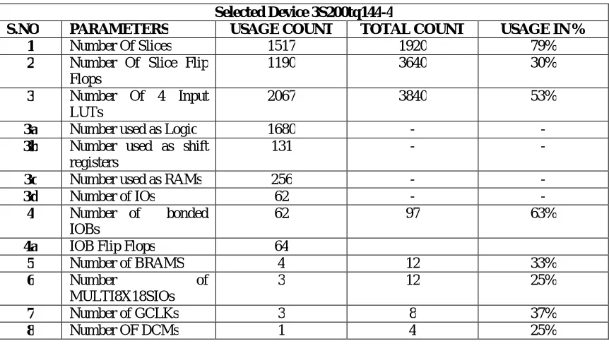
Table 2 specifies the performance of micro-Blaze parameter which is tested by Xilinx platform studio. The input image which is used for the lifting based DWT image compression is as shown in the Fig.9.
Table- 2: Performance of Micro-Blaze Parameters
The considering input image is in RGB format but for compression purpose it should be converted into gray image with the help of matlab. This gray image having the pixel values in the range from ( 0 to 255).For observing compression results we use the visual basic and some commands. When the code running is completed the input image visible like in Fig-9.
Speed Grade -4
Minimum period 12.384 ns
Maximum frequency 80.749 MHZ
Maximum combinational path delay
3.44ns
Selected Device 3S200tq144-4
S.NO PARAMETERS USAGE COUNT TOTAL COUNT USAGE IN %
1 Number Of Slices 1517 1920 79%
2 Number Of Slice Flip Flops
1190 3640 30%
3 Number Of 4 Input
LUTs
2067 3840 53%
3a Number used as Logic 1680 - -
3b Number used as shift registers
131 - -
3c Number used as RAMs 256 - -
3d Number of IOs 62 - -
4 Number of bonded
IOBs
62 97 63%
4a IOB Flip Flops 64
5 Number of BRAMS 4 12 33%
6 Number of
MULTI8X18SIOs
3 12 25%
7 Number of GCLKs 3 8 37%
Fig-9: Input Image
After completion of first level of compression the output image is as shown in Fig.10, then the DWT transform applied to the first level of compressed image, then we get further compressed image.
Fig-10: 1-Level Compressed Output Image
The second level of compressed output image as shown in Fig.11.After completion of compression the LLi(i=1,2,3) is having the output image and high band levels containing the noise, pixel values.
In this process pixel values are varied at each level of compression. By using this method the size of image should be reduced but their resolution and quality should be maintained at good without losing any data information.
Fig-11: 2-Level Compressed Output Image
When apply the inverse discrete wavelet transform (IDWT) then get the output image as input image is shown in fig 12.In this IDWT process those three steps of lifting is helpful to get original image as output and after getting the output image the pixel value should be same as the input image pixel value. This total procedure should be completed with the help of visual basic.
Fig-12: Inverse Discrete Wavelet (IDWT) Image VI. CONCLUSION
memory efficient VLSI architecture can be design for 3-D DWT based on lifting method. It should have the memory efficient and high speed VLSI modular for throughput and it reduces the delay time. This kind of EDK can be extended to other applications of embedded system.
REFERENCES
[1] Tze-Yun Sung, Hsi-Chin Hsin Yaw-Shih Shieh and Chun-Wang Yu, “Low-Power Multiplierless 2-D DWT and IDWT Architectures Using 4-tap Daubechies Filters”, Seventh International Conference on Parallel and Distributed Computing, Applications andTechnologies, December 2006.
[2] Abdullah AL Muhit, Md. Shabiul Islam and Masuri Othman, “VLSI Implementation of Discrete Wavelet Transform(DWT) for image processing”,2nd International Conference on Autonomous Robots and Agents, 13-15 December 2004.
[3] Motra A. S. Bora P.K. and Chakrabarti I., “An efficient hardware implementation of DWT and IDWT”,Conference on Convergent Technologies for Asia-Pacific Region, 15-17 October 2003.
[4] Yun-Nan Chang and Yan-Sheng Li, “Design of highly efficient VLSI architectures for 2-D DWT and 2-D IDWT”, IEEE Workshop on Signal Processing Systems, 26-28 September 2001.
[5] David S. Taubman, Michael W. Marcellin, “JPEG 2000-Image compression, fundamentals, standards and practice”, Kluwer academic publishers, Second Edition, 2002.
[6] K. K. Parhi and T. Nishitani, “VLSI architecture for discrete wavelet transforms,” IEEE Trans. Very Large Scale Integr. (VLSI) Syst., vol. 1, no. 2, pp. 191–202, Jun. 1993.
[7] P.Wu and L. Chen, “An efficient architecture for twodimensional discrete wavelet transform,” IEEE Trans. CircuitsSyst. Video Technol., vol. 11, no. 4, pp. 536–545, Apr. 2001.
[8] W. Sweldens, “The new philosophy in biorthogonal wavelet constructions,”in Proc. SPIE., 1995, vol. 2569, pp. 68–79.
[9] Daubechies and W. Sweldens, “Factoring wavelet transform into lifting steps,” J. Fourier Anal. Appl., vol. 4, no. 3, pp. 245–267, Mar. 1998.
[10] Wei Zhang,Zhe Jiang,Zhiyu Gao, and Yanyan Liu,”An efficient VLSI architecture for Lifting based discrete wavelet transform,”IEEE Trans.Circuits and systems,vol.59NO.3,pp. 158-162,Mar.2012.