Wireless LED Matrix Display System
Chandani Maurya1, Dr. M. B. Mali2
Post Graduation Student, Department ofE & TC, Sinhgad College of Engineering, Pune, India 1 Head of Department, Department of E & TC, Sinhgad College of Engineering, Pune, India 2
ABSTRACT: Notice boards are common in the different institutions and are used daily. The notices are normally
printed on the papers and then it displayed. The proposed system can announce a notice by just typing on the computer. If there is no notice, along with temperature and humidity, time will be displayed. Here, ZigBee module is used for wireless communication. At receiver side, LED matrix board will display a notice which is controlled by microcontroller. GPS module is interfaced with microcontroller to display real time. At transmitter side, computer is used where ZigBee module is interfaced via USB to serial converter. An application is developed to write a notice. When anything is written on that window, it displayed immediately on the board. With the help of this application, notices can be transmitted from any computer if needed.
KEYWORDS: GPS module, LED matrix board, Notice display
I. INTRODUCTION
There is a long process involved in order to put up the notices on the notice board in the institutions. Urgent notices should be displayed immediately and it should be highlighted. In this digitalized era in the institutions the notices are still displayed in the board and required paper work. Sometimes the important notices are missed which should be known immediately. Whereas the LED displays are widely used in Public areas for various type of display, because of large screen, long life and flexible display.
The proposed system is very useful is this area. It can announce a notice just by typing on a computer in the application window. The LED matrix board contains 24 rows and 120 columns of LEDs, display type of 5×7 LEDs for one character. Hence, three rows and in each row 20 characters can be displayed at a time. The built application window is easy to use. The authentication feature is also added so that there will be no misuse. If needed, the authorization can be provided to different person and the limited authority can be added like remove the ‘delete’ button for the lower authority member. The ZigBee module is used to receive and transmit the data wirelessly between microcontroller and LED matrix board. Often ZigBee device is used in the mesh network to transmit data over longer distances for wireless communication. Additionally, here the matrix board will display the temperature, humidity and the time. For the timing information GPS model is used.
II. RELATED WORK
In [1] the work is done on Notice display but PIC16F77A is being used for controlling the system and for display the notice only LCD is used. Zigbee module is connected to the computer via MAX232. A voltage regulator is designed to automatically maintain a constant voltage level. It is used to stabilize the DC voltages used by the processor and other elements. It is used in the Transmitter section to stabilize the voltage at the output of MAX232 before passing it to Zigbee Module. Zigbee module on the receiver side is interfaced with UART (Universal Asynchronous Receiver/ Transmitter) of Micro-Controller PIC16F877A. Micro-Controller receives the message from Zigbee module on receiver side and displays it on the LCD screen. It also provides Synchronization between Transmitter and Receiver.
III.PROPOSED SYSTEM ARCHITECTURE
Fig.1 shows the transmitter side of this system. The application window is prepared in Visual studio 2010 in which the notices are to be typed. When the send button is pressed in this window the data is transmitted through ZigBee module via USB to serial converter.
Fig.1. Block diagram of transmitter side
Fig.2 shows the receiver side of this system. Temperature, Humidity sensor and GPS module are connected to microcontroller directly. Microcontroller will receive the data from these components and after processing the data it will send to the display. If any data (notice) is received by Zigbee module the notice will be displayed immediately. These three data (temperature, humidity and time) will be displayed at the particular interval of time. Meanwhile the other saved notices is shown one by one.
Fig.2. Block diagram of receiver side
IV.SYSTEM IMPLEMENTATION
A. Used Hardware and Software
1. Used Hardware
a) Microcontroller: ATmega64
b) LED Matrix Board: 24 rows and 120 Columns of LEDs c) Temperature and Humidity sensor: LM35 and HC201 d) GPS Module: SIM28ML
e) ZigBee Module: XBee-PRO S2B
Computer
USB to serial
converter ZigBee module
Power supply
ATmega64
LED Matrix Display
ZigBee module S2 pro Humidity
Sensor HC201 Temperature sensor LM35
2. Used Software
a) Transmitter side: Microsoft Visual Studio 2010 (Programming: .Net) b) Receiver side: AVR Studio 4 (Programming: Embedded C)
c) To upload hex file in the chip: PROGISP (Ver 1.68) d) To configure the ZigBee module: X-CTU
e) PCB Designing: PCB Artist 2.1
B. Display Board
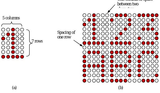
In the display board for the one character 5×7 LEDs are used as shown in Fig. 3(a). The used LEDs matrix board can display 20 characters in one line and contains three lines. There is one row of LEDs is used to provide space between two lines. Similarly, one column of LEDs is used for the separation of two characters. Fig. 3(b) is the example of matrix display of two lines and three character each line.
(a) (b)
Fig.3. (a) 5×7 LEDs for one character (b) Matrix display of two lines and three character each line
Fig. 4 shows the one part of the display panel. It contains 40×24 LEDs, which is mounted by 8×8 dot matrix. Similarly two more parts are built, and together it will be board of 120×24 LEDs.
Fig.4. The one part of display board.
C. Interfacing of Display Board with Microcontroller
Fig. 5 shows the interfacing between microcontroller and LED matrix board. As there are large no of LEDs are driven, it requires large amount of current as well as large no of pins. So, here for the columns shifters are used, which
One column of space between two characters
Spacing of one row 5 columns
are connected to LEDs via driver (register and transistor combination). The rows of the display board are connected to microcontroller through ULN2803. This extra circuitry will help to draw the more current which is required by the display. Due to the use of shifter no of pins required are reduced. Here three ULN driver and fifteen shifters are used. Cause of the use of shifter, for the column only three pins are required of the microcontroller. This shifter will provide serial input and parallel output.
Fig.5. Interfacing between microcontroller and LED matrix board.
V. RESULTS AND DISCUSSION
The application window is prepared in the Visual studio 2010. Fig. 6 shows the application window, which contains one Text box, five buttons (Send, Highlight, Show all, Delete, and Delete all) and a progress bar. Its outlook can be changed easily if wanted.
Fig.6. The application window when a notice is send
to rows
to columns
Serial data out Serial data in Serial data in
Parallel data out Storage register clock input
Shift register clock input
PF0 PF7 . . . PA0 PA7 PC0 PC7
LED Matrix Board Microcontroller
ATmega64
Driver
. . .
. . .
Shifter 74595 Shifter 74595
Driver
T1 T2 PD5
It shows the notice is written in the text box and 'send' button is pressed. The ‘Show all’ button will display the all notices which are stored in the microcontroller. The notices are fetched one by one from the memory of the microcontroller and it is send to the transmitter side where in the application windows these notices are shown. When we press ‘Delete’ button it will delete the notice which one is ask for and ‘Delete All’ will delete the all notices.
Fig. 7 shows the data (notices), which is saved in the EEPROM of microcontroller, is displayed after pressing the ‘Show all’ button. These notices are extracted one by one and displayed in the text box of application window.
Fig.7. The saved data (notices) are displayed after pressing ‘show all’ button
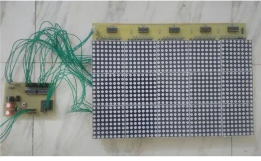
Fig. 8 shows the LED Matrix Board with controller card. Here the display board is connected to the controller card and 12v, 5A supply is provided.
Fig.8. LED matrix board with controller card
Fig.9. (a) The Final display board with Notice display. (b) Temperature, Humidity and Real Time is Shown.
VI.CONCLUSION
The implemented proposed system will be very useful for urgent notice. The developed application window is used to write the notice so that when anything is written on that window it display immediately on the board after pressing the ‘send’ button. With the help of this system notices can be transmitted from any computer if needed, it only requires extra ZigBee module. After the installation process, it is easy to use and notices can be changed at any time. Authentication to different authority can be provided for security purpose. This system is very useful for urgent notices.
REFERENCES
1. Ajinkya Gaikwad and Tej Kapadia, “Wireless Electronic Notice Board,” International Journal on ACTE , International Journal on Advanced Computer Theory and Engineering (IJACTE), vol. 2, Issue 3, pp. 1-4, 2013.
2. M.A. Kader, Md. Mahbubur Rahman, “LED Matrix Based Digital Learning Display for Children With Wireless Control,” 17th International Conference on Computer and Information Technology (ICCIT),International Islamic University Chittagong (IIUC) Chittagong, Bangladesh, pp. 397-400, April 2014.
3. Shih-Mim Liu and Yan-Chi Chou, “Color Calibration for a Surrounding True-Color LED Display System by PWM Controls,” IEEE Transiction on Electronics, vol. 61, no.11, pp. 6244-6252, Nov 2014.
4. Xinge Jiang Min Chen and Zhujun Li Xuanmin Chen, “Wireless real-time LED display control system based on single chip microcontroller,” 7th International Conference on Computer Science & Education,Guangzhou Institute of Railway Technology ,Guangzhou ,P R China, pp. 951-952, July 2012.
5. N.B.Bhawarkar and G.V. DehankarȦ, “ARM Based Electronic Notice Board through Zigbee with Room Lights Control using PIR Sensor,” International Journal of Current Engineering and Technology, vol 4, no.2, pp. 753-756, April 2014.
(a)