Effect of Intake Valve Mode and Spray Cone
Angle on Wall Fuel Film and Air Fuel Mixture
Formation of PFI Gasoline Engine
Musaab O. El-Faroug
Assistance Professor, Mechanical Engineering Department, Faculty of Engineering, El Imam El Mahdi University,
Kosti 11588, Sudan
ABSTRACT: The air-fuel mixture formation process affects the performance and pollutant emissions of PFI gasoline engine. Hence it becomes necessary to consolidate the numerical methods which are able todescribe such a complex physical process. The impacts of intake valve mode and spray cone angle on wall fuel film and equivalence ratio were investigated using Computational Fluid Dynamics (CFD) PFI engine simulation. The results showed that, the wall fuel film with use of open valve injection mode (OVI) was a lower compared with the closed valve injection mode (CVI). It also observed that the air-fuel mixture when applied OVI mode was richer compared with CVI mode. In addition, increase the spray cone angle is better for decrease the oil film.
.
KEYWORDS: Intake valve mode; spray cone angle; wall fuel film; mixture formation; PFI gasoline engine.
I. INTRODUCTION
An engine with a port fuel injection has been occupied for numerous years, spray features and air-fuel formation are still the matter of investigation. The adjustment of the fuel-air mixture formation performs a significant character in order to improve the combustion procedure and decrease the total emissions from an SI engine. The fuel vaporization is configurations, the droplet size distribution, the temperature of intake port and valve, affected by the fuel properties, spray cone angle, injection timing, valve and port and the manifold absolute pressure [1]. The liquid fuel that is injected will be atomized and evaporates shaping fuel vapor. In addition, the fuel droplets formed through atomization relating to their size are also reliable for wall film. Tinier atomization decreases the air-fuel mixing time and reduces wall-wetting, consequent in afurther uniform air-fuel mixture [2].
A number of researchers [3-6] have studied the impact of diverse operating conditions on evaporation and spray of air fuel mixture. Brenn et al.[3] reported that the air flow velocity was a significant factor for spray dynamic performance. Oliveira [4], who noticed that the closed valve injection ensued in better derivability of the engine equated to open valve injection. Dementhon and Vannobel [7] examined the spray behavior in the intake manifold, and the outcomes revealed that the injection timing had a main impact on spray characteristics.
Due to the continuous restrictions on engine pollutants, many experimental reports have applied multi strategies to reduce emissions from PFI engines [8-10]. The combustion characteristics and emissions produced from PFI engines are affected by air-fuel mixing, it is controlled by the fuel-injection processes and gas flow. Hence, to explore the wall film and equivalence ratio of air fuel mixture, the CFD PFI engine simulation was applied to simulate the gasoline formation. The fuel applied alternatively of gasoline was iso-octane, since its boiling point is 99°C, which close to the fifty percent evaporation point of gasoline [11].
II. METHODOLOGY
Engine model
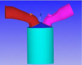
The engine studied was a single-cylinder, two intake valves, four-stroke PFI engine. It has a 75 mm bore, 84.4 mm stroke and 10.5 compression ratio. However, to simulate the intake stroke and compression stroke the simulation mesh includes of intake port, exhaust port and cylinder, which is shown in Fig. 1. The basic grid scale of 4mm is used with adaptive grid encryption technology (Adaptive Mesh Refinement, AMR) to enhance the calculation precision. Grid encoding level is 3; the local encryption grid size is 0. 5mm.
Fig. 1: Engine single cylinder model
Spray and evaporation models
KH-RT spray breakup model [12-14] was applied. The model supposes that at exit of the nozzle, the liquid core is formed, and the core fractures down due to the unsteadiness getting up over liquid core surface providing bigger droplets. These greater droplets from the core are controlled by the KH-RT model. The droplet evaporation is controlled by heat transfer equations and mass conservation [12]. The droplet collisions are depended on the No Time Counter (NTC) model [15]. In addition, Frossling Model used for the droplet evaporation [16]. Reynolds-Averaged Navier–Stokes (RANS) established on the subject of the group (RNG) k– -model is applied to simulate turbulence for an air-fuel mixture inside the combustion chamber.
Boundary conditions
The start time of calculation is -460 °CA and end at 0 °CA. Assume that the last cycle is completely burned, the residual gas in the inside cylinder and exhaust pipes is N2, CO2 and H2O, and only air is present in the inlet of intake
port. The fuel injection starts at -440 ° CA, the total fuel mass injected is 2.5 × 10⁻⁵, the intake port temperature is 310K and inflow pressure is 0.56 bar, the total number of droplets is 50000, the nozzle diameter is 0.25 mm.
III.RESULTSANDDISCUSSION
Intake valve mode
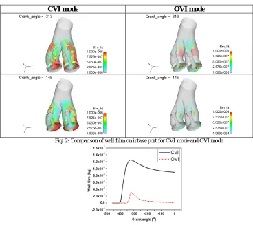
CVI mode OVI mode
Fig. 2: Comparison of wall film on intake port for CVI mode and OVI mode
Fig. 3: Wall film mass for CVI mode and OVI mode.
Fig. 4 displays the in-cylinder equivalent ratio distribution for the intake and compression strokes through two intake port modes. From the above results, we found that the oil film stick on the intake port for CVI is higher than OVI, these results mean that the amount of fuel inter the engine cylinder is higher for OVI compared with CVI, and that will effect on equivalence ratio distribution. It observed from Fig. 4 the air-fuel mixture when applied OVI mode was richer compared with CVI. On the other hand, at the compression stroke, the air-fuel mixture is getting more and more uniforms compared with intake stroke. In general, the homogeneity of air fuel mixture for OVI is better than CVI mode. The combustible air fuel mixture at the time of spark was richer for OVI, these result may suggest that, the amount of fuel used for these two modes should be difference and that mean reduces the fuel consumption when OVI mode has been applied. Fig. 5 shows the equivalence ratio versus crank angle, it can be seen that, the equivalence ratio for air fuel mixture at the time of spark for CVI mode and OVI mode equal 1 and 1.7, respectively.
Fig. 4: Comparison of equivalence ratio distribution for CVI mode and OVI mode.
Fig. 5: Equivalence ratio distribution versus crank angle
Spray cone angle
The spray characteristics are impacted by fuel pressure, fuel temperature, fuel properties, and injector geometry, etc. In this part we have tested to decline the wall wetting and explore the impacts of spray cone angle on wall film and equivalence ratio. The contrast of wall-film for various spray cone angle 10o and 15o can be seen in Fig. 6 and Fig. 7. It observed that, the increase spray cone angle from 10o to 15o leads to decrease the wall film. At the beginning of injection, the wall film was smaller and increased with the raise the crank angle until reach the maximum value, and after that the oil film decreased due to evaporation process.
Spray cone angle 10o Spray cone angle 15o
Fig. 7: Oil film mass for spray cone angle 10 and 15 degree.
Fig. 8 and Fig. 9 displays the equivalent ratio distribution inside cylinder for the intake stroke and compression stroke. It can be seen that, the top centre part of the cylinder has more concentrated with air fuel, increase the spray cone angle leads to a higher equivalence ratio compared with narrow spray cone angle, this also attributed to the more wall wetting stick on intake port when a narrow spray cone angle applied. On the other hand, at the compression stroke, the air fuel is getting more and more uniforms compared with intake stroke.
Spray cone angle 10o Spray cone angle 15o
Fig. 8: comparison of equivalence ratio distribution for different spray cone angle.
IV. CONCLUSION
• Open valve injection mode showed a significant decrease in wall film compared with closed valve injection mode. While, the air-fuel mixture at the time of spark ignition was richer for open valve injection.
• Wide spray cone angle is good for decrease the wall film but the narrow spray cone angle is better for increasing the level of turbulent and enhance the combustion characteristics.
ACKNOWLEDGMENT
The author would like to thank Professor Maji Luo and Wang Yinanat Wuhan University of technology for their support during this research.
REFERENCES
[1] Zhao, F.-Q., M.-C. Lai, and D.L. Harrington, The spray characteristics of automotive port fuel injection-a critical reviews. 1995, SAE Technical Paper.
[2] Sureshkumar, J., et al., Effect of Fuel Spray Inclinations on Spray Characteristics in a Port Fuel Injected Engine-A CFD Study. 2013, SAE Technical Paper.
[3] Brenn, G., et al., Unsteady gasoline injection experiments: comparison of measurements in quiescent air and in a model intake port. 1995, SAE Technical Paper.
[4] Panão, M.R.O., A.L. Moreira, and D.F. Durão, Effect of a cross-flow on spray impingement with port fuel injection systems for HCCI engines. Fuel, 2013. 106: p. 249-257.
[5] Bianchi, G., et al., CFD analysis of injection timing and injector geometry influences on mixture preparation at idle in a PFI motorcycle engine. 2007, SAE Technical Paper.
[6] Luan, Y., N.A. Henein, and M.K. Tagomori, Port-Fuel-Injection Gasoline Engine Cold Start Fuel Calibration. 2006, SAE Technical Paper. [7] Dementhon, J. and F. Vannobel. Phase Doppler anemometry in gasoline sprays: in atmosphere and in a steady flow rig. in Proceedings of
ILASS Europe Conference on Spray and Aerosol, Guildford, UK. 1991.
[8] El-Faroug, M.O., et al., Experimental Investigation on the Stability of Hydrous Ethanol Gasoline Blends and Emission Products from SI Engine. 2016 International Conference on Energy Development and Environmental Protection (Edep 2016), 2016: p. 21-26.
[9] El-Faroug, M., et al., Spark Ignition Engine Combustion, Performance and Emission Products from Hydrous Ethanol and Its Blends with Gasoline. Energies, 2016. 9(12): p. 984.
[10] Luo, M., et al., Particulate Matter and Gaseous Emission of Hydrous Ethanol Gasoline Blends Fuel in a Port Injection Gasoline Engine. Energies, 2017. 10(9): p. 1263.
[11] Lindgren, R. and I. Denbratt, Modeling gasoline spray-wall interactions and comparison to experimental data. 2004, SAE Technical paper. [12] Ali, M.J.M., et al., Effect of Timing and Location of Hotspot on Super Knock during Pre-ignition. 2017, SAE Technical Paper.
[13] Reitz, R.D. and R. Diwakar, Effect of drop breakup on fuel sprays. 1986, SAE Technical Paper. [14] Reitz, R.D. and R. Diwakar, Structure of high-pressure fuel sprays. 1987, SAE Technical Paper.
[15] Schmidt, D.P. and C. Rutland, A new droplet collision algorithm. Journal of Computational Physics, 2000. 164(1): p. 62-80.