20th International Conference on Structural Mechanics in Reactor Technology (SMiRT 20) Espoo, Finland, August 9-14 2009 SMiRT 20-Division V, Paper ID-NR 1780
Fuel Assembly Two-Beam Dynamic Model Response to Faulted Condition Loads
Sudhir J. Shah*
Berenger d’Uston
AREVA NP Inc., Fuel America
AREVA NP Inc., Fuel America
P.O. Box 10935
P.O. Box 10935
Lynchburg, VA-24506-0935, USA
Lynchburg, VA-24506-0935, USA
(434) 832-2306 phone
(434) 832-2629 fax
[email protected]
Gary T. Williams
AREVA
AREVA NP Inc., Fuel America
P.O. Box 10935
Lynchburg, VA-24506-0935, USA
Keywords
:
Core Structural Seismic ModelABSTRACT
Current analytical faulted core models used to analyze seismic or Loss-of-Coolant Accident (LOCA) are built by means of one equivalent beam per assembly. In this paper the fuel assembly is modeled with two beams, utilizing the rudimentary finite element technique of grouping items with common properties as they would exhibit common behaviors. Hence, the two-beam fuel assembly model provides more realistic internal forces for the subsequent stress analysis of the fuel assembly components. With the “two-beam” linear model it is possible to benchmark more closely to both the first natural frequency and lateral stiffness, since it represents the more realistic internal connections and boundary conditions. Also the two beam model allows analysts to predict the fuel assembly analytical lateral impact test results closer to the test results and eliminates the need for the representation of the internal stiffness of the grid. Lastly the two-beam model is a good base for any further development, particularly for introducing the non linear rod to grid mechanical behavior.
In the paper, the two-beam-per-assembly model is briefly discussed first and then results of a seismic study for a row of assemblies are addressed. The model is excited by input acceleration at its boundaries. Specifically these boundaries are the lower and upper core plates at the time-history of the core supporting plates. These input data come from the reactor system analysis.
1.
INTRODUCTION
impacts will occur. The “equivalent” stiffness is comprised of two springs in series: Ki from rods to the center (internal stiffness), and 2Ke (Ke: through grid stiffness) from the center to the edge.
In the two beam model, the finite element model of the fuel assembly is constructed with two beams – one representing the total number of the guide tubes and the instrument tube and the other beam representing the total number of the fuel rods. Horizontal rigid shear ties between the beams are placed at each grid elevation, which eliminates the need for determining the in-grid stiffness from the fuel assembly lateral impact test. The guide tubes are tied also at the upper and lower nozzles. Hence a two-beam model provides a better approximation of the fuel assembly by grouping all the guide tubes and the instrument tube as one beam and by grouping all the fuel rods as a second beam. Splitting the components based on their right boundary conditions helps in providing accurate characteristics of the fuel assembly.
The paper presents a comparison of grid impact loads and reaction forces of the seismic analysis performed on a seven-assembly row model with the one-beam model per assembly and the beam model per assembly. The purpose of the study is to show not only the validity of the two-beam per assembly model but also to show that the two-two-beam per assembly model is better suited for the fuel assembly component analyses.
2.
FUEL ASSEMBLY 2-BEAM MODEL DESCRIPTION
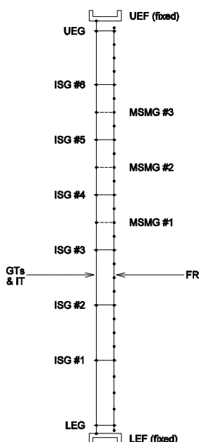
A finite-element model of the fuel assembly is created by 2 beams as shown in Figure 1. The first beam represents the total number of the guide tubes and the instrument tube, which forms the cage of the fuel assembly. The second beam represents the total number of the total fuel rods. In order to better account for the real mass distribution. there are 4 elements in each grid-span for each fuel rod beam (3 intermediate nodes per grid span) and 1 element in each span for each combined guide tube and instrument tube beam. Rotational springs for the guide tubes and the fuel rods are placed on their respective beams at each grid location and are attached to the end nodes of the model, which are fixed. This stiffening effect is partially from the intermittent shear ties between the rods supplied by each grid. The end rotations of the guide tube beam are fixed to represent the presence of the nozzles. The tested prototype fuel assembly had the mid-span mixing grids which, as shown in Figure 1 are incorporated into the model. The translations of the guide tubes and the fuel rods at the grid level are assumed to be the same. That means that the grids remain horizontal. A sensitivity study on the fuel assembly lateral impact test is done to show that the discretization of the fuel rod beam with 3 intermediate nodes per grid level is enough to remove the representation of the internal stiffness from the model.
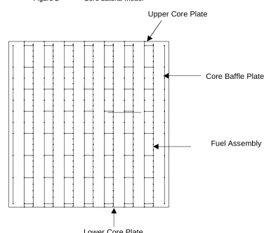
Once the model is developed, horizontal springs representing the through-grid stiffness are incorporated into the model to allow for the grid impact. The through-grid springs are attached to the “cage” beam model at each grid level. The individual model is duplicated to represent any number of fuel assemblies in a given row in the core. A row of seven assemblies is used in the study. An assembled model of a row of assemblies is shown in Figure 2. Inter-assembly and outer assembly gaps are also incorporated with the through-grid springs which then complete the core model.
3.0
Core Model Study
.
Analyses are performed with the parameters that correspond to 12 ft. fuel assembly design with mid span mixing grids using the qualified version of the AREVA dynamic analysis computer code. The studies are performed with accelerograms correspond to a spectrum used in the US nuclear program, with maximum accelerations of 0.4g Safe Shutdown Earthquake at the reactor vessel level. The gap values between assemblies and between outer assemblies and core baffle plates are real ones, derived from core geometry. The analyses are performed for 20 seconds of seismic excitation. The analytical model uses the direct explicit integration method for the solution, together with the Guyan elimination technique to save computing time without any loss of accuracy.
The maximum impact load and the reaction moments of the end fittings of seven-row configuration for the one-beam-per assembly model and the two-beam-per assembly model are shown in Table 1. From the results, it can be seen that the two-beam-per-assembly model is slightly less conservative than the one-beam-per-assembly in terms of the results, however both the models described here are quite comparable.
4.0
Conclusion
The fuel assembly is modeled with two beams, utilizing the rudimentary finite element technique of grouping items with common properties and boundary conditions as they would exhibit common behaviors. The two-beam-per assembly model provides the right boundary conditions of the fuel assembly and makes better allowance for matching some basic fuel assembly characteristics. Also the model is more accurate in representing the dashpot region of the guide tubes.
The 2-beam fuel assembly model does not require the calculations of the in-grid stiffness. Hence the use of this model would eliminate the requirement of determining the in-grid stiffness of the spacer grids and the mid-span mixing grids through the rather extensive prototype fuel assembly testing.
The current methods are sufficient for assessing the safety margins for the seismic and LOCA loads. However, the development of methods presented in this paper is logically more realistic and precise and provides a sound basis for determining internal and external forces to the fuel assembly structure.
Table 1 Fuel Assembly Forces with 1-Beam and 2-Beam Models
Type of Beam Model Fuel Assembly Forces
1-Beam Model 2-Beam Model
Maximum Grid Impact Force Ref. 0.762
Upper End Fitting Moment Ref. 0.966
Figure 2 Core Lateral Model