Roof Crush Analysis of Passenger Car for
Vehicle Safety and Crashworthiness
Prajwal S1, Ullas G1, Akshay M1, Syed Huzaifa1, Arun R2, Santhosh Gaidhankar2
U.G. Student, Department of Mechanical Engineering, Sai Vidya Institute of technology, Rajankunte, Bangalore, India1
Assistant Professor, Department of Mechanical Engineering, Sai Vidya Institute of technology, Rajankunte,
Bangalore, India2
ABSTRACT: Rollover accidents of a car are the most occurring accidents that we see in our daily lives. The passengers experience major injuries like neck, head and spine injuries. So, to reduce the injuries of a passenger from major fatalities it is important to provide safety in the car. Though safety is provided by seat belts and airbags during accidents, the passenger must have sufficient space for survival in the car during accidents. The roof of the car must have high strength to resist the crush force to avail the passenger some space for survival. Therefore, in this project, we have carried out roof crush test using Federal Motor Vehicle Safety Standards (FMVSS216) standards in LS dyna software. We have used Hypermesh software to mesh the model and to apply boundary conditions to it. And the rigid plate is used to crush the car roof as specified by FMVSS216 standards. The rigid plate is oriented on the car roof as specified by Insurance institute of highway safety (IIHS). And an alternate material is used to the car roof structure to the baseline model to check the crashworthiness of new material. The outcome of test results of the new material’s strength to weight ratio (SWR) was compared to baseline model and the new material is proposed for the roof (B-pillar) which is found to be more crashworthy.
I.INTRODUCTION
Rollover crashes, especially in the country, are usually very destructive events. Vehicle damage often includes deformation of the roof and its supporting structures. Head and neck injuries are common, and associated with roof deformation. Strengthening of the roof is suggested as an appropriate countermeasure for such injuries.
There are currently no rules covering the strength of the roofs of passenger cars. Similarly, there are no roof crush strength regulations and consideration of such standards appears to be of a low priority. The Department of Transport, through the Federal Office of Road Safety, has requested a review of the costs, benefits and feasibility of introducing a new Design Rule based on the US rule, which is Federal Motor Vehicle Safety Standard 216. This would apply only to passenger cars, and not include convertible models
This Project was also being carried out to provide a solution to comply with the forthcoming BS-6 and BNVSAP norms about emissions and safety respectively.
Types of Rollovers
Tripped-NHTSA data show that 95% of single-vehicle rollovers are tripped. This happens when a vehicle leaves the roadway and slides sideways, digging its tires into soft soil or striking an object such as a curb or guardrail. The high tripping force applied to the tires in these situations can cause the vehicle to roll over.
E.g. Soft soil, Guardrail, Steep Slope
FMVSS 216 Roof crush standards
FMVSS 216, Roof Crush Resistance, establishes strength requirements for the passenger compartment roof of passenger cars, multipurpose passenger vehicles, trucks and buses with a GVWR of 2722 kilograms or less. The purpose of the standard is to reduce deaths and injuries due to the crushing of the roof into the passenger compartment in rollover accidents. The standard does not apply to school buses and passenger cars that conform to the dynamic rollover test requirements of FMVSS 208, Occupant Crash Protection, and S5.3 by means that require no action by passenger car occupants. It also does not apply to convertibles, except for optional compliance with the standard as an alternative to the rollover test requirements in S5.3 of FMVSS.
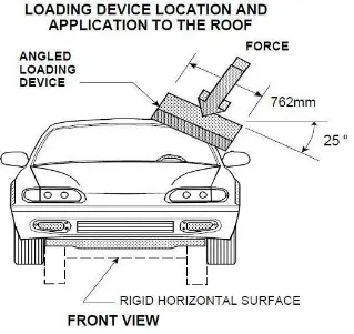
The prescribed static loading device is a rigid unyielding rectangular block 762 millimetres by 1,829 millimetres. It shall not move more than 127 millimetres to achieve the specified resistive load when applied to the forward edge of a vehicle’s roof – see Figures 1 and 2. The resistive load to be achieved is 1½ times the unloaded vehicle weight (UVW) of the test vehicle or 22,240 Newtons, whichever is less.
The force shall be applied in a downward direction perpendicular to the lower surface of the static loading device at a rate of not more than 13 millimetres per second until reaching the compliant resistive load. The test shall be completed within 120 seconds. The static loading device shall be guided throughout the test so that it moves, without rotation, in a straight line with its lower surface oriented as follows and as shown in Figures 1 and 2
Figure 2 Static loading device front view
II. LITERATURE SURVEY
Rollovers constituted not less than 22%, and 27% of all rural crashes on road with 100 or 110 km/h speed limit. In a study of rural crashes in South Australia to which an ambulance had been called there were 18 rollovers in 48 car crashes, 37.5% (Ryan et aI, 1988).
In Victoria, 5.7 % of casualty accidents to cars are rollovers (1975 and later "cars", where cars include taxis, station wagons, utilities and panel vans, involved in 19871990 accidents). The corresponding proportion of casualties (fatal and admitted to hospital) is 11% of total casualties. For trucks, the proportion of casualties due to rollover is 18.2%.
Investigation of the rollover process was first undertaken as early as 1959 (Shoemaker) and has been intermittently studied since. Garrett (1968) and Garrett and Stem (1968) reported that rollovers were more common among small cars than large cars and injury was more common in small car rollover accidents. Volkswagens were involved in rollover accidents without collisions twice as frequently as Corvairs and four times as frequently as large American cars.
Strother et al (1984) used velocity-time diagrams for an idealised rollover to show that the head impacts the roof at the same moment that the roof is loaded by the ground and interpret this to mean that roof deformation would not increase (head or neck) injury.
Presently Insurance Institute for Highway Safety (IIHS)is working to improve the safety standards
III. METHODOLOGY
To suggest alternative material to the traditional sheet metal (CRCA rolled sheets) by utilizing CAE practices for addressing the Design and analysis phase and considering the Vehicle Manufacturers to provide effective solution by offering a competitive advantages while complying with the relevant standards in Automotive Engineering.
The main objective of this Project is to protect passengers during car rollover accidents and reduction of mass of the car roof helps in reducing the overall mass to improve the efficiency of the car.
The work flow of this project work is as follows,
1. Identifying alternative material to the traditional sheet metal (CRCA rolled sheets) to reduce weight. 2. Suggest alternatives over Material and/or Process for mass manufacturing.
3. Utilizing CAE practices for addressing the Design and Analysis phase. 4. Comparing with the relevant standards in Automotive Engineering.
Work Flow chart of the analysis Phase
Dual-phase steel (DP steel) is a high-strength steel that has a ferrite–martensitic microstructure (Fig3). DP steels are produced from low or medium carbon steels that are quenched from a temperature above A1 but below A3 determined from continuous cooling transformation diagram. This results in a microstructure consisting of a soft ferrite matrix containing islands of martensite as the secondary phase (martensite increases the tensile strength). Therefore, the overall behaviour of DP steels is governed by the volume fraction, morphology (size, aspect ratio, interconnectivity, etc.), the grain size and the carbon content. For achieving these microstructures, DP steels typically contain 0.06–0.15 wt.% C and 1.5-3% Mn (the former strengthens the martensite, and the latter causes solid solution strengthening in ferrite, while both stabilize the austenite), Cr & Mo (to retard pearlite or bainite formation), Si (to promote ferrite transformation), V and Nb (for precipitation strengthening and microstructure refinement).The desire to produce high strength steels with formability greater than micro alloyed steel led the development of DP steels in the 1970s.
Pre-processing (Hypermesh)
Mid-surface extraction
Geometry cleanup
Meshing Quality check Analysis setup export Processing (LS-dyna solver)
Selection of solver
Import to solver
Run the analysis
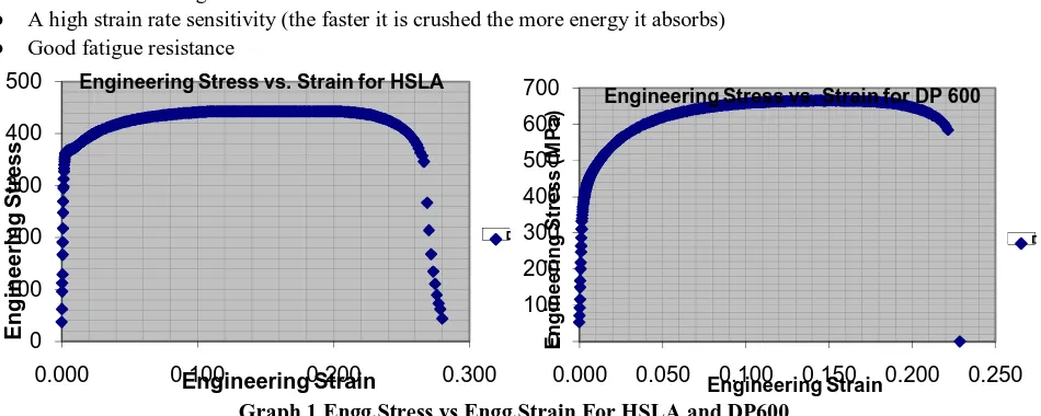
DP steels have high ultimate tensile strength (UTS, enabled by the martensite) (Graph1) combined with low initial yielding stress (provided by the ferrite phase), high early-stage strain hardening and macroscopically homogeneous plastic flow (enabled through the absence of Lüders effects). These features render DP steels ideal materials for automotive-related sheet forming operations.
The steel melt is produced in an oxygen top blowing process in the converter, and undergoes an alloy treatment in the secondary metallurgy phase. The product is aluminium-killed steel, with high tensile strength achieved by the decomposition with manganese, chromium and silicon.
Their advantages are as follows
● Low yield to tensile strength ratio (yield strength / tensile strength = 0.5)
● High initial strain hardening rates
● Good uniform elongation
● A high strain rate sensitivity (the faster it is crushed the more energy it absorbs)
● Good fatigue resistance
Graph 1 Engg.Stress vs Engg.Strain For HSLA and DP600
Figure 3 Ferrite–Martensitic microstructure Graph 2 DP600 VS HSLA
0 100 200 300 400 500
0.000 0.100 0.200 0.300
En g in e e ri n g Str e s s Engineering Strain Engineering Stress vs. Strain for HSLA
E 0 100 200 300 400 500 600 700
0.000 0.050 0.100 0.150 0.200 0.250
E n g in e e ri n g S tr e s s ( M P a ) Engineering Strain
Engineering Stress vs. Strain for DP 600
IV. SIMULATION RESULTS
The analysis is carried out with defined boundary conditions. The results are compared between baseline and modified Model.
Displacement and Stress Plots for HSLA with 2.5mm thickness
Displacement plot of HSLA 2.5mm thickness
Displacement and Stress Plots for DP600 with 1.4mm thickness
Displacement plot of DP600 1.4mm thickness
Displacement and Stress Plots for DP600 with 1.2mm thickness
Displacement plot of DP600 1.2mm thickness
Stress plot of DP600 1.2mm thickness
Comparison of Energy curves of HSLA and DP600
DP600
HSLA
Tabulation of Results
SL.NO Material Thickness Displacement(mm) Stress(Mpa) Force(KN)
1. HSLA490 2.5mm 141.96 1.423 80
2. DP600 1.4mm 126.24 0.623 73
3. DP600 1.2mm 138.44 1.870 67
V. CONCLUSION
The vehicle roof with new material is complaint with the relevant standards by comparison analysis with CAE which is beneficial for weight reduction and hence to improve vehicle efficiency and satisfy requirements of vehicle manufacturers.As the results indicate usage of DP 600 reduces the impact of rollover accidents on the passengers and also reduces the weight of the vehicle hence enhancing its efficiency and safety. Using DP600 material for all the load bearing components or parts of the vehicle can cause a drastic reduction of weight hence increasing its efficiency and also helps in reducing the amount of emission from the vehicle. The weight of the Car was reduced by 5.2kgs after changing the material to DP600 and also the strength was increased which enhanced the energy absorbing capacity to withstand Impact loads. Also, Providing Better integrity for the side windows, Increasing A and B pillar strength and Providing more energy-absorbing padding in the head-strike areas can further increase the safety. In order to understand the impact of change in thickness of the same material (DP600) we carried out another iteration and found that the results changed drastically for just 0.2mm change in thickness.
REFERENCES
[1] Attewell R G and Traficante R (INTSTAT), Federal Office of Road Safety Serious Injury Database: 1993 tabulations, Report OR18, Federal Office of Road Safety, Department of Transport, 1995
[2] Bahling G S, Bundorf R T and Moffatt E A et al, Rollover and drop tests: the influence of roof strength on injury mechanics using belted dummies , SAE 902314, in Proceedings, 34th Stapp Car Crash Conference, Society of Automotive Engineers, 1990
[3]. Bahling G S, Bundorf R T, Moffatt E A and Orlowski K F, The influence of increased roof strength on belted and unbelted dummies in rollover and drop tests, Journal of Trauma, 38(4) : 557-563, 1995
[4].Cohen D, Digges K and Nichols H, Rollover crashworthiness classification and severity indices, in Proceedings, 12th International Technical Conference on Experimental Safety Vehicles, 1989
[5.] Council F M and Reinfurt D W, Safety issues related to mini-cars from a roadway perspective , SAE 870233, in Proceedings, SAE International Congress and Exposition, Society of Automotive Engineers, 1987
[6]. Crash Kings, Rallying, Duke Videos, 1994
[7]. Digges K H, Malliaris A C, Ommaya A K and McLean A J, Characterisation of rollover casualties, in Proceedings, International IRCOBI Conference on the Biomechanics of Impact, International Research Council on the Biomechanics of Impact, 1991
[8].Chakraborti, P.C.; Mitra, M.K. (2007-10-27), "Microstructure and tensile properties of high strength duplex ferrite-martensite (DFM) steels", Materials science & engineering, 466(1–2): 123–133, doi:10.1016/j.msea.2007.02.042.
[9].Tasan, C.C.; Hoefnagels, J.P.M.; Diehl, M.; Yan, D.; Roters, F.; Raabe, D. (2014), Strain localization and damage in dual phase steels investigated by coupled in-situ deformation experiments and crystal plasticity simulations, 63, International Journal of Plasticity, p. 198-210. [10].Degarmo, E. Paul; Black, J T.; Kohser, Ronald A. (2003), Materials and Processes in Manufacturing (9th ed.), Wiley, ISBN 0-471-65653-4. [11].Fallahi, A. (2002), "Microstructure-Properties Correlation of Dual Phase Steels Produced by Controlled Rolling Process" (PDF), Journal of material science & technology, 18 (5): 451–454, archived from the original (PDF) on 2016-03-03.