University of Windsor University of Windsor
Scholarship at UWindsor
Scholarship at UWindsor
Electronic Theses and Dissertations Theses, Dissertations, and Major Papers
2008
The Development of an Electrostatic Storage Ring for Low Energy
The Development of an Electrostatic Storage Ring for Low Energy
Electrons
Electrons
David Ronald Tessier University of Windsor
Follow this and additional works at: https://scholar.uwindsor.ca/etd Part of the Physics Commons
Recommended Citation Recommended Citation
Tessier, David Ronald, "The Development of an Electrostatic Storage Ring for Low Energy Electrons" (2008). Electronic Theses and Dissertations. 8284.
https://scholar.uwindsor.ca/etd/8284
LEQO'(L\B~
THE DEVELOPMENT OF AN ELECTROSTATIC STORAGE RING FOR LOW ENERGY ELECTRONS
By
David R. Tessier
A Dissertation
Submitted to the Faculty of Graduate Studies through the Department of Physics in Partial Fulfillment of the Requirements for
the degree of Doctor of Philosophy at the University of Windsor
Windsor, Ontario, Canada 2008
"The Development of an Electrostatic Storage Ring for Low Energy
Electrons"
by
David Ronald Tessier
APPROVED BY:
R.C. ~hiell, External Examiner Trent University
Department of Physics
. Kedzierski Department of Physics
Department of Physics
~~
K.Taylor, Ch ~ n s e
Department of Chemistry & Biochemistry
Declaration of Co-Authorship/ Previous Publication
I. Co-Authorship Declaration
I hereby declare that this thesis incorporates material that is result of joint research, as follows:
The instrument that is unique in design and construction was made to function by the author through the designs and concepts presented in Chapters 4 and 5. The results and analysis of Chapters 5 and 6 were performed by the author. This thesis also incorporates the outcome of a joint research undertaken with Dr. Benjamin G. Birdsey and Aaron J. Alderman under the supervision of Dr. Peter Hammond and Dr. Frank H. Read. The collaboration is covered in Chapter 2 of the thesis. Section 3.2 was a collaborative project, and with the exception of section 3.3 of Chapter 2, the key ideas and primary contributions were performed by the author. The physical design of the instrument as presented in section 1.0 of chapter 3 was performed by Drs. Peter Hammond and Timothy J. Reddish prior to my start date of summer 2004. Section 2.0 of Chapter 3 was based on the research of Ying Niu as published as a major paper in 2006, and was re-designed and re-engineered by the author.
I am aware of the University of Windsor Senate Policy on Authorship and I certify that I have properly acknowledged the contribution of other researchers to my thesis, and have obtained written permission from each of the co-author(s) to include the above material(s) in my thesis.
I certify that, with the above qualification, this thesis, and the research to which it refers, is the product of my own work.
II. Declaration of Previous Publication
This thesis includes four original papers that have been previously published/submitted for publication in peer reviewed journals, as follows:
Thesis Publication title/full citation Publication status Chapter
Chapter 2 Stability Criteria for a Passive Electrostatic In preparation Non-Relativistic Charged Particle Storage
Device
Chapter 3 The Practical Realization of the Electron In Preparation Recycling System
Chapter 4 D.R. Tessier et.al., The Development of an Published Electrostatic Charged - Particle orbit
Recycling System, Australian IOP Congress, Proceedings, 50, WC0328, (2006), Editor(s):
Chapter 5 D.R. Tessier et.al., Passive Electrostatic Published Recycling Spectrometer of Desk-Top Size for
Charged Particles of Low Kinetic Energy, Phys Rev Lett, 99, 253201, (2007)
I declare that, to the best of my knowledge, my thesis does not infringe upon anyone's copyright nor violate any proprietary rights and that any ideas, techniques, quotations, or any other material from the work of other people included in my thesis, published or otherwise, are fully acknowledged in accordance with the standard
referencing practices. Furthermore, to the extent that I have included copyrighted material that surpasses the bounds of fair dealing within the meaning of the Canada Copyright Act, I certify that I have obtained a written permission from the copyright owner(s) to include such material(s) in my thesis.
ABSTRACT
A cyclical electrostatic device, referred to as an Electron Recycling Spectrometer (ERS) for charged particles is described and demonstrated. The system has been developed with storing electrons with typical kinetic energies of tens of eV. The orbital path for the electrons is 0.65 m long and defined through the application of design voltages to two series of cylindrical lenses inserted between two identical hemispherical deflector analyzers. The ERS design concept exploits the very low scattering cross sections in electron-molecule collisions, where the majority of electrons do not interact with the target. Unscattered electrons are collected and passed back through the ERS for another collision opportunity in the interaction region.
The design of the charged particle optics and the basic operating characteristics of the storage ring are discussed. An overall transfer matrix is formed for the ERS by individual transfer matrices of charged particle optics. The conditions of stability within the ERS are extracted from the fundamental inequality involving the trace of the total transfer matrix. The stability lies within a region in a resonant-like pattern, defined by the focal lengths of the electrostatic lenses.
Electron orbit spectra are displayed for a number of ERS operating conditions. Exponential decay rates, average orbit time, and mean electron energy are presented for each spectrum. Analysis was performed by fitting each orbit or "peak distribution" with a Gaussian curve. The noble gases helium and argon were used as the scattering target for electron detection. Ionization spectra provide long term storage times, as an electron beam must be present in the system to produce an ion species. The optimal ion storage exponential decay lifetime achieved is - 55 µs, which is target gas pressure limited and corresponds to - 200 orbits of the 0.65 m orbital circumference for a drop in particle yield of e *. Studies of beam dynamics were performed, analyzing the width evolution of each peak as a function of orbit number. Separate modes were observed that are non-linear with respect to the orbit number.
I hereby dedicate this thesis to
ACKNOWLEDGEMENTS
I am most grateful to Dr. Timothy J. Reddish for his supervision and support of this
project, and for his scrutiny of this thesis. I would also like to thank Dr. Peter Hammond
for his support and guidance of my work throughout my time on this project. In addition,
Dr. Hammond's invaluable comments and suggestions toward the development of the
storage ring. I would also like to express my thanks towards Dr. Hammond's students Dr.
Benjamin G. Birdsey and Aaron A. Aldermen for their contributions. I greatly appreciate
Dr. Frank H. Read, for not only his contribution to the matrix modeling of the storage
ring, but also his invaluable contribution to electron optics in general.
I would like to take this opportunity to express my sincere gratitude to Drs. Reddish and
Hammond for their recommendation for my reclassification from the MSc. to the PhD
program.
Special thanks to Dr. Dominic Seccombe for his work on the storage ring in addition to
his training and general laboratory techniques that he imparted on me. In addition to Ying
"Mike" Niu who overlapped a year with me during his masters work on the storage ring,
including initial assembly and electrical wiring, with modeling and construction of
electron gun. I would also like to recognize all the undergraduate students that spent time
in my lab during my graduate studies and provided me with assistance during their stay.
In particular I would like to thank: Daniel Trojand, Michael Sullivan, Theresa Spanjers,
Violeta Piasecka, and Brandon Disher.
I would like to thank Sabrina Ludmann for her translation of articles written in German to
English. I would also like to thank Natalie Crumb for proof reading this manuscript and
correcting Grammar and Spelling. Special thanks to Mr. Sinisa Jezdic for designing the
necessary electronic instruments and advice on all electronic devices that were designed
and build by the author. A special thanks to Mr. Louis Beaudry and Mr. Eric Clausen for
all their work on the construction of elements and maintenance of vacuum pieces for the
I would also like to extend my personal gratitude toward Arathi Padmanabhan and all my fellow graduate students and post-doctoral fellows of the physics department for their support and engaging conversation during my stay at the University of Windsor. I would also like to thank all my friends and family for moral support and encouragement throughout my eight years at the University of Windsor.
TABLE OF CONTENTS
DECLARATION OF CO-AUTHORSHIP/ PREVIOUS PUBLICATION 111
ABSTRACT v
DEDICATION VI
ACKNOWLEDGEMENTS vu
LIST OF TABLES xm
LIST OF FIGURES XIV
I. INTRODUCTION
1.1 AN OVERVIEW OF CHARGED PARTICLE TRAPS AND STORAGE RINGS
1.2 TRAPPING
1.2.1. The Localized Paul Trap 1.2.2. The Linear Paul Trap 1.2.3. The Penning Trap
1.2.4. Linear Electrostatic Trap 1.2.5. Neutral Particle Trap 1.3 POSITRON ACCUMULATOR 1.4 STORAGE RINGS
1.4.1. The Ion Storage Ring (Paul Trap Design) 1.4.2. Synchrotron Ring
1.4.3. Electrostatic Rings:
1. Brookhaven Storage Ring ii. ELISA
iii. Flair iv. Desiree 1.5 SUMMARY REFERENCES 1 2 3 3 4 7 9 11 13 15 15 17 18 19 20 21 22 23 24
II. THEORETICAL - ELECTRON STORAGE FOR RACETRACK 26
GEOMETRY
2.1 INTRODUCTION TO ELECTRON OPTICS 2.1.1 Electrostatic Lenses and Focusing Conditions 2.1.2 Helmholtz - Lagrange Relation
27
28
2.1.3 Hemispherical Deflector Analyzer (HDA) 2.2 THE TRANSFER MATRIX
2.2.1 Background
2.2.2 The Electron Recycling System (ERS) 2.3 STABILITY
2.3.1 Phase Space
2.3.2 Constraints Imposed on the Transfer Matrix
1. Unity Matrix
11. Deviations from Unity Matrix 111. Generalized Expression 1v. Asymmetric Lens Setup
34 36 37 39 41 42 44 45 47
49
53
v. Aberrations 57
2.3.3 Stability Modeling 59
4. SUMMARY ~
REFERENCES 61
III. EXPERIMENT AL I - SYSTEM DESIGN 63
3.1 THE ELECTRON RECYCLING SYSTEM 64
3 .1.1 Overview 64
3.1.2 Cylindrical Lens 72
3.1.3 Vacuum Chamber 73
3.2 ELECTRON GUN 74
3.2.1 Gun Design 74
3.2.2 Pulsing Circuit 81
3.3 VOLTAGE POWER SUPPLY SCHEMATIC 85
3.4 SUMMARY 86
REFERENCES 87
IV. EXPERIMENT AL II - ELECTRON BEAM INJECTION 88
4.1 FIRST ATTEMPTS AT ELECTRON INJECTION AND STORAGE 89
4.1.1 Introduction 89
4.2 STORAGE ACHIEVED
4.2.1 Scattering off tungsten ring 4.2.2 Results: tungsten ring injection
1. Preliminary data
11. Optimized data 4.3 GUN POSITIONED ON HDA 4.4 PULSING SCHEMES
4.5SUMMARY REFERENCES 94 95
101
102
104
106
110 114 115V. RESULTS AND DISCUSSION - GUN POSITIONED ON HDA 116
5.1 SYMMETRIC SETUP 5 .1.1 Introduction
5.1.2 Data of (15
I
15) Pass Energy Setup 5.1.3 Bunch Analysis5.2 ASYMMETRIC SETUP 5 .2.1 Introduction
5.2.2 Metastable Background 5.2.3 (4 I 18) Pass Energy 5.2.4 ( 4 I 15) Pass Energy
5.2.5 (7
I
15) Pass Energy 5.2.6 (9 I 18) Pass Energy5.2.7 Comparison: Asymmetric Pass Energies 5.3 IONIZATION STUDIES
5.4SUMMARY REFERENCES
VI. ANOMALOUS BEHAVIOUR
6.1 NON - COHERENT EVALUATION 6.1.1 Preliminary Results
6.12 Peak Width Saturation for Symmetric Pass Energy
6.1.3 Peak Width Saturation for Asymmetric Pass Energy 148 6.1.4 Peak Width Saturation at Slightly Asymmetric Pass Energy 149
6.1.5 Summary 151
6.2 OSCILLATIONS ABOUT OPTIC AXIS 151
6.2.1 Symmetric Pass Energy 152
6.2.2 Asymmetric Pass Energy 153
6.2.3 Small Oscillations 155
6.3 SUMMARY 156
REFERENCES 158
VII. CONCLUSION 159
APPENDICES 1-A 1-B 1-C 1-D 1-E 2. 3. 4. 5. 6.
Mst Matrix for Symmetric Setup Eigenvalues of Mst
Solving MsT for Mss = - I
Components of Mss (non - unity case) Solving Mst (Asymmetric Setup) Photographs
Gun Pulse Shapes
Hemisphere Pulse Shapes Typical Voltages
Additional Spectra
VITA AUCTORIS
PERMISSION OF REPRINT
LIST OF TABLES
Page 1. Accelerating definitions of lenses 31 2. Properties of hemispherical deflector analyzer 35
3. Resonant Voltages 53
LIST OF FIGURES
Page
1.1 Paul trap 4
1.2 Linear Paul trap 5
1.3 Penning trap 7
1.4 Penning trap with split ring electrodes 8
1.5 Penning trap with laser cooling, and utilizing both E and B fields 9
1.6 Linear electrostatic trap (Zajfman' s group) 10
1.7 Sextupole field from hyperbolic magnets 12
1.8 Trajectory focusing in a sextupole field 13
1.9 Penning - Malmberg trap 13
1.10 Penning - Malmberg Trap with buffer gas cooling 14
1.11 Paul Type Racetrack Storage Ring 16
1.12 Synchrotron storage ring 18
1.13 ELISA storage ring 20
1.14 FLAIR storage ring 21
1.15 DESIREE 22
2.1 Basic schematic of Electron Recycling System (ERS) 27
2.2 Collimation 29
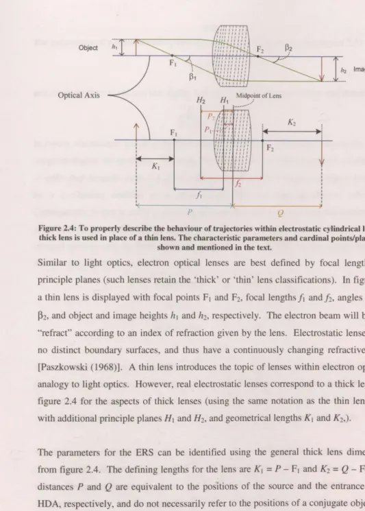
2.3 · Thin lens 29
2.4 Thick lens 30
2.5 Triple Cylindrical Lens 32
2.6 Dispersion within an 180° electrostatic hemispherical deflector analyzer 35
2.7 Ray trace within a field free region 38
2.8 Phase Space ellipse 43
2.9 Schematic diagram of thick lens 46
2.10 Stability graphs 52
2.11 Computer simulation of electron trajectories within ERS 55 2.12 CP03D computer simulation of electron beam cross sections within 60
the ERS
3.2
Schematic of source stack65
3.3
Schematic of interaction stack65
3.4
Channeltron Detector67
3.5
Detailed schematic of ERS69
3.6
Dimensions of inner and outer hemisphere71
3.7
Dimensions of a lens for the ERS72
3.8
Cylindrical lens showing ERS parameters72
3.9
Deflector system75
3.10
Deflector elements with dimensions76
3.11
Deflector system77
3.12
Schematic of grid and filament support system77
3.13
Aperture dimensions of electron gun78
3.14
The emission region of a filament tip78
3.15
The accelerating region79
3.16
Modified gun schematic79
3.17
Filament cradle and grid dimensions80
3.18
Electron Gun dimensions80
3.19
Support base for aperture lens80
3.20
Electron Gun Pulsing Circuit Schematic82
3.21
Driving Pulse for Electron Filament83
3.22
Fall-time of electron driving pulse83
3.23
Pulse output with capacitor84
3.24
Power supply circuit for the ERS storage ring85
4.1
Venn diagram of phase space parameters89
4.2
Differential Cross Section for electron - argon scattering91
4.3
Energy distribution of electrons excited by electrons of copper96
4.4
Secondary Electron Distribution for Inelastic scattered electrons96
4.5
Injection schematic for wire ring setup97
4.6
Pulsing sequence for filament contact potential and source region98
4.7
Computer modeling of source region including field lines and electron99
4.8 Effect of the Target wire on a parallel beam 99
4.9 Data of early wire ring setup 102
4.10 Data acquisition setup 103
4.11 Electron peak spectrum for preliminary data for wire ring setup 103
4.12 Linear plot of the data of figure 4.11 104
4.13 Electron peak spectrum for optimized data for wire ring setup 105
4.14 Linear plot of the data of figure 4.13 105
4.15 Peak width evolution of the data for the data of figure 4.13 106
4.16 Logarithmic plots of the peak height and area variation for the 106 data of figure 4.13
4.17 General Schematic of an Operational amplifier 107
4.18 Schematic of updated ERS storage ring 108
4.19 Electrical schematic for the gun elements 109
4.20 Describing the energy of the electrons according to the effects 109 of all the floating points
4.21 An analogue of the pulse ramp as a series of narrow - energy steps 112
4.22 Power supply layout for the first trial of optimizing injection 112
4.23 Selection points on the filament driving pulse for the energy of the 112 stored electrons
4.24 Point matching of filament and hemisphere pulse, second trial of 113 optimizing injection
5.1 Basic Schematic of ERS 118
5.2 Data of electron signal collected at the interaction region for a setup 119 of 15.0 eV pass energy and 15.0 eV ERS energy
5.3 Linear plot of the data of figure 5.2 119
5.4 Variation in peak height and peak area for the data of figure 5 .2 120
5.5 Beam width variation as a function of orbit number for the linear 121 electrostatic trap
5.6 Peak width variation for the data of figure 5.2 123
5.7 Example, production of a metastable state 125
5.8 Logarithmic plot of an electron beam that has traveled three quarters 126 around the ring followed by a metastable peak
of 40.0 eV
5 .10 Linear plot of the data of figure 5. 9 127
5 .11 Variation in peak width for the data of figure 5. 9 128
5.12 Data of electron signal collected at the interaction region for a setup 128 of 4 eV Top HDA and 15.0 eV bottom HDA pass energy, for an ERS
energy of 22.0 eV
5.13 Linear plot of the data of figure 5.12 129
5.14 Variation in peak width for the data of figure 5.12 129
5.15 Logarithmic plot of electron signal collected at the interaction region 130 for a setup of 7 e V Top HDA and 15.0 e V bottom HDA pass energy,
for an ERS energy of 25.0 eV
5 .16 Linear plot of the data of figure 5 .15 130
5.17 Peak width variation for the data of figure 5.15 131
5.18 Data of electron signal collected at the interaction region for a setup 132 of 9 eV Top HDA and 18.0 eV bottom HDA pass energy, for an ERS
energy of 50.0 eV
5.19 Linear plot of the data of figure 5.18 132
5.20 Peak width variation for the data of figure 5.18 133
5.21 Helium ionization spectra taken within the ERS operating in the 135 recycling and non-recycling modes
5.22 Helium ion time-of-flight distributions 136
5.23 Plot of lifetimes as a function of pressure 137
6.1 Peak width spectra with the linear electrostatic trap by Zajfman's group 143
6.2 Peak width saturation with the linear electrostatic trap by Zajfman's group 144
6.3 Data of electron signal collected at the interaction region for a setup 145 of 12.0 eV pass energy and 30.0 eV ERS energy, for preliminary results within the exotic features section
6.4 Linear plot of the data of figure 6.3 145
6.5 Electron peak spectrum, for the ERS operating in peak width saturation 146 mode
6.6 Linear plot of the data of figure 6.5 146
6.7 Peak width variation of the data of figure 6.5 147
6.8 Data of electron signal collected at the interaction region for a setup 148 of 9 eV Top HDA and 15.0 eV bottom HDA pass energy, for an ERS
6.9 Linear plot of the data of figure 6.8 148
6.10 Peak width variation of the data of figure 6.8 149
6.11 Data of electron signal collected at the interaction region for a setup of 150 12 eV Top HDA and 15 eV bottom HDA pass energy, for an ERS energy
of 30.0 e V, for the ERS operating in peak width saturation mode
6.12 Peak width variation of the data of figure 6.11 150
6.13 Data of electron signal collected at the interaction region for a setup of 152 15 eV Top HDA and 15 eV bottom HDA pass energy, for an ERS energy of 15.0 eV, for the ERS operating in 'oscillation about the optic axis mode'
6.14 The variation in the peak height for the data of figure 6.13 152
6.15 Linear plot of the data of figure 6.13 153
6.16 Data of electron signal collected at the interaction region for a setup of 153 8 eV Top HDA and 15 eV bottom HDA pass energy, for an ERS energy of 30.0 eV, for the ERS operating in 'oscillation about the optic axis mode'
6.17 . Linear plot of the data of figure 6.16
6.18 Peak height variation of the data of figure 6.16
154
154
6.19 Data of electron signal collected at the interaction region for a setup of 155 18 eV Top HDA and 18.0 eV bottom HDA pass energy, for an ERS energy of 36.0 eV, for the ERS operating in 'oscillation about the optic axis mode'
6.20 Linear plot of the data of figure 6.19
6.21 Peak height variation of the data of figure 6.19
6.22 Peak area variation of the data of figure 6.19
155
156
CHAPTER 1: INTRODUCTION
1.1 AN OVERVIEW OF CHARGED PARTICLE TRAPS
2
AND STORAGE RINGS
1.2 TRAPPING
3
1.2.1
The Localized Paul Trap
3
1.2.2
The Linear Paul Trap
4
1.2.3
The Penning Trap
7
1.2.4
Linear Electrostatic Trap
9
1.2.5
Neutral Particle Trap
11
1.3 POSITRON ACCUMULATOR
13
1.4 STORAGE RINGS
14
1.4.1
The Ion Storage Ring (Paul Trap Design)
15
1.4.2
Synchrotron Rings
17
1.4.3
Electrostatic Rings:
18
.
Brookhaven Storage Ring
19
I.
ii.
ELISA
19
iii. Flair
20
iv. Desiree
21
1.5 SUMMARY
22
1.1 AN OVERVIEW OF CHARGED PARTICLE TRAPS AND
STORAGE RINGS
A variety of instruments and methods have been developed over the last 50 to 60 years that are designed to trap and confine charged particles. An overview of these methods is presented in the chapter and will give the reader an appreciation of the types of rings and applied electric and magnetic fields used to store charged particles (or neutral particles in special traps). Storage of charged particles can be static or dynamic. In the static sense, the conglomerate will be centered at a point within the trap, whereas dynamic traps confine the particles in one or two dimensions while propagating along a single axis. The methods and practices presented here place this thesis in a historical context.
Storage and confinement experiments occur in the form of ion and atom traps, neutral polarized particle traps, magnetic storage rings, and electrostatic storage rings. The instruments in point can have the following effects on the particles: improve precision of knowing the particle's position and energy, or select its quantum state. A particle or beam that is confined will be labeled by a set of parameters i.e. x ± bx, p ± op, E ± oE (position, momentum, and energy). The magnitude of o is proportional to the uncertainty in the measurement, which is determined by the type and quality of the operations listed above. Thus, optimal confinement will minimize the uncertainty 8, and produce highly precise results in any particle collision or irradiation experiment ( either trapping or stored orbits).
formation. Moving from the static trap concept, accelerating and non-accelerating rings will send charged particles circulating a closed ring, and in some applications improve the energy resolution within the ring. Generally, charged particle rings store projectile charged particles to be aimed at a target, rather than the static trapping setup, where the target was held and a projectile beam was directed at it. Storing within a static trap allows for experiments of a different nature to be performed due to the low temperature and high density of the target. The chapter will conclude with the presentation of electrostatic charged particle storage rings due to its relevance to this thesis.
1.2 TRAPPING
The general form of Laplace's equation in free space is given in equation 1.1 [Jackson (1998)]:
(1.1)
A static electric field E(x, t) = E(x) satisfies the Laplace equation. However, there are no maxima or minima, and therefore the E field cannot contain charged particles within a fixed region. The problem of trapping was circumvented by the Paul and Penning trap designs. Wolf gang Paul created a trap by using both DC and AC electric fields.* On the other hand, the Penning model traps ions through a DC electric field with the addition of a static magnetic field B [Paul ( 1990)].
1.2.1 The Localized Paul Trap
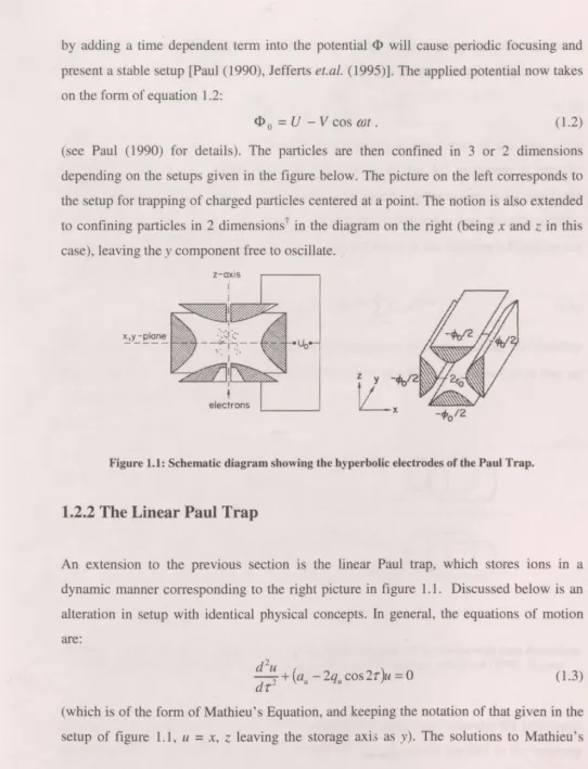
by adding a time dependent term into the potential <I> will cause periodic focusing and present a stable setup [Paul (1990), Jefferts et.al. (1995)]. The applied potential now takes on the form of equation 1.2:
<I> 0
=
V - V cos mt . (1.2)(see Paul (1990) for details). The particles are then confined in 3 or 2 dimensions depending on the setups given in the figure below. The picture on the left corresponds to the setup for trapping of charged particles centered at a point. The notion is also extended to confining particles in 2 dimensions t in the diagram on the right (being x and z in this case), leaving they component free to oscillate.
electrons
Figure 1.1: Schematic diagram showing the hyperbolic electrodes of the Paul Trap.
1.2.2 The Linear Paul Trap
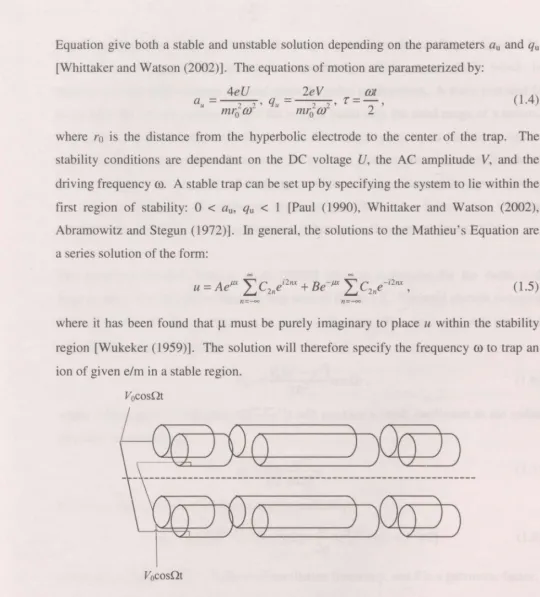
An extension to the previous section is the linear Paul trap, which stores ions in a dynamic manner corresponding to the right picture in figure 1.1. Discussed below is an alteration in setup with identical physical concepts. In general, the equations of motion are:
d2
dr~
+
(au
-2qu cos2r)u=
0 (1.3)(which is of the form of Mathieu's Equation, and keeping the notation of that given in the setup of figure 1.1, u = x, z leaving the storage axi.; as y). The solutions to Mathieu's
Equation give both a stable and unstable solution depending on the parameters au and qu
[Whittaker and Watson (2002)]. The equations of motion are parameterized by:
4eU 2eV mt au
=
2 2 ' qu=
2 2 'r
=
-2 'mr0 {J) mr 0 {J)
(1.4)
where r0 is the distance from the hyperbolic electrode to the center of the trap. The stability conditions are dependant on the DC voltage U, the AC amplitude V, and the driving frequency
ro.
A stable trap can be set up by specifying the system to lie within the first region of stability: 0 < au, qu < 1 [Paul (1990), Whittaker and Watson (2002), Abramowitz and Stegun (1972)]. In general, the solutions to the Mathieu's Equation are a series solution of the form:00 00
A µx """°'C i2nx B -µx """°'C -i2nx
U
=
e L...J 2ne+
e L...J 2ne , (1.5)n=-oo n=-oo
where it has been found that
µ
must be purely imaginary to place u within the stabilityregion [Wukeker (1959)]. The solution will therefore specify the frequency
ro
to trap an ion of given e/m in a stable region.Vocosnt
Vocosnt
Figure 1.2: A side view of the linear Paul Trap, displaying cylindrical electrodes with time dependent and independent (not shown) voltages, dashed line represents storage axis [Paul (1990), Raizen
(1992)].
the charged particles in they direction (keeping in practice to the labeling of figure 1.1).
The AC component of the potential is commonly radiofrequency (RF), which is
transverse to the entire storage axis and gives the radial confinement. A static potential V
is added to the end electrodes to hold the trapped beam over the axial range of y meters.
However, there is an increase in the loss of the charged particles in this setup due to
dispersion in the beam as it oscillates over the axis that guides some of the particles out of
the storage region. This style of trapping provides a longer interaction region with a
sacrifice in trap lifetime. To elaborate, the linear trap lifetime is a few seconds, whereas
the Paul Trap may be a few hundred seconds [Thompson, Harmon and Ball (2002)].
The group of Raizens [Raizens et.al. (1992)] give an expression for the fields and
frequencies of the particles within the trap seen in figure 1.2. The total electric potential
(DC plus AC) can be rewritten as
cp
= Vo - V0cosrot. The near axis AC potentialcomponent is approximated by:
V, (
2 2)
V
=
O X - y cos QtAC 2R2 ' (1.6)
where a high driving frequency (Q » 1 s-1) will produce a small oscillation in the radial
direction with frequency:
_ 1 qV0
m, -
Ji
mnR 2 • (1.7)Moreover, the static potential can be approximated by:
(1.8)
where ro2 (= (2kqV0
!m)
112
) is the axial oscillation frequency, and k is a geometric factor.
As seen in equation 1.8 the fields are mass and charge dependant. The length of the rods
can be extended to - 6 m to provide a long drift region that allows for time-of-flight
measurements. In this configuration one can scan through the voltages Vo and Vo to make
the trap function as a mass spectrometer [Paul ( 1990)].
1.2.3 The Penning Trap
Similar to the Paul Trap design with respect to the physical geometric setup of the
apparatus, the Penning trap stores the charged particles in the center of two pairs of
endcaps, as in figure 1.3. Incidentally, the electrodes are usually hyperbolic, although an
extension can be made to a linear cylindrical containment region, similarly done in the
linear Paul trap, without causing any considerable limitations to storage. The Penning trap
chronologically precedes the Paul trap, which is expected, since the Penning trap contains
less complex design features. To elaborate, the qesign includes a planar electric field that
will confine the trapped particles in two dimensions (x and y by convention), leaving the
third dimension (labeled z by convention) open which cannot be closed with an static
electric field as indicated by the Laplace equation [ equation 1.1] and as stated above
under the general discussion for trapping. For trapping to occur, the z direction must be
closed by some external force. In the field of electrodynamics, once the notion of a static
electric field has been eliminated as an option, the next economical choice is a static
magnetic field (Wolf gang Paul took this one step further and successfully implemented a
time - dependant electric field in place of the static magnetic field) [Paul ( 1990), Rich
and Wesley (1972)]. The presence of both electric and magnetic field, results in a
spiraling motion on any charged particle that tries to extricate itself away from the center.
Figure 1.3: Schematic diagram displaying the Penning trap with two pairs of endcaps with the magnetic field directed top to bottom (typically produced by a pair of toroidal magnets) [Brown and
Since the particles are moving with some finite (small) velocities they will precess within
the x - y plane at a cyclotron frequency given by:
qB
V c =
-m
and will oscillate in the z axis at the axial frequency:
( )
1/2
=
2qU0v
z
2 'mR0
(1.9)
(1.10)
where Uo is the applied voltage (i.e. <p = Uo). The center of the ion bunch rotates about
the trap axis at a magnetron frequency of:
v
=
.!.
v
-(.!.
v
2 __!.
v2J
112m
2 c 4 c 2 z (1.11)
The magnetron motion 1s ultimately the trapping process, as it confines the charged
particles to the center of the trap oscillating indefinitely [Brown and Gabrielse (1986)].
Endcap
electrode
(upper)
Figure 1.4: A modern version of the Penning Trap with DC electric fields on the inner electrodes, an axial magnetic field, and six spinning electrodes to provide a rotating electric field that influences the
trapped plasma [Hasegawa et.al. (2005)].
A more modem design of the Penning trap can be seen in figures 1.4 and 1.5, which
display the fields that are responsible for creating the 6radient toward the center. Figure
1.4 shows an example of the Penning trap used to confine a plasma cloud, whereby the
trapping fields remain as the static electric and magnetic field. The addition of the
which will affect its shape and density [Hasegawa et.al. (2005)]. The presence of the laser in the next figure (figure 1.5) has the purpose of 'cooling' the ionic cluster (which is the process of reducing the kinetic energies of the individual particles, and hence lowering the effective temperature of the ion cloud). The cluster is free to rotate about the z axis; the rotational freedom that can lead to particle escape is controlled by the rotating electric field [Bollinger et.al. (2000)].
ro1a1jng quadrupole
fie.Id (top-view) ++
~
intensified
CCDc:amera
'
.
I \
I / I
~ strobing
/ t~\
\-,.-.
/
\ ~ d e f l e c t m\
/
~
~ e n ++ 0
s1de-view
I
' '
coamt'rn f/51
'::'
•':::
::
: : 0:::: (::"'
'Bo'I
XL
y axial cooling beamFigure 1.5: A representation of a modern Penning trap design, with static electric field, magnetic field, rotating electric field, and laser cooling [Bollinger et.al. (2000)].
1.2.4 Linear Electrostatic Trap
The linear electrostatic trap developed by Zajfman's group [Pedersen et.al. (2001), Zajfman et.al. (1997), and Zajfman et.al. (2004)] is a modern instrument to contain ions dynamically within a desktop sized apparatus. Making use of electrostatic elements only, ions are contained on a linear storage axis between two multi-element lenses. The lens setup on the right ( of figure 1.6) is held at fixed potentials; however they can be made to vary in order to optimize the storage efficiency of the trap.
The lens on the left in figure 1.6 will begin with grounded electrodes to allow for ion injection. Following injection, an electric switch that is connected to the lens elements changes the grounding to the elements to the applied voltages { Vs, Z1 } that are identical to
the right lens. Once the ions have entered through the left lens (grounded and field free) they continue to the right and get decelerated by the right lens, stop and get repelled in the opposite direction to which they entered. During the previous stage, the electric switch has been activated to change the voltages on the left lens from ground, such that they are set up equal to the lens on the right in order to slow, stop, and repel the ions back again on
a heading toward the right lens again. Iteratively, the ions therefore 'bounce' from the right to the left, which essentially confines them in the region between the two lenses or "mirrors". This setup is analogous to an optical resonator in laser optics, where the right and left lenses simulate the function of the concave mirrors used in those applications.
R R R R
r:
-+-4-l - + - 4 1 - - - . . . . - -........... _ _ _ ..........-1 ·
f
Ek v,
8
6.J
f-
Field free regionEJ
H
t
...
-
- -
-
---
-
-
-
- -
-- -
-
-
-
-
-
-
-
-
----
-
- -
- -
-
----
--- - - - --
--· --
--
-IN
I
l'li
I
r1
F
-;,
22r;,
rr
I
ri
r
I
ou~~wr
lv
LL
lL=407mm
Figure 1.6: Diagram of the Zajfman ion trap. The ion beam is injected from the left, (the entrance electrodes are pulsed to ground). The other electrodes are used for focusing, slowing, and repelling the ions. Neutral particles are formed by electron capture of the ions, which escape the trap and are
monitored by a microchannel plate detector downstream [Zajfman et.al. (1997)].
system. Following collimation, the ion beam is directed into the trap through the back of
the lens element (left, in the figure).
Each lens consists of five cylindrical elements that are labeled El to ES in the figure. In
addition, a grounded lens element, A 1, is placed at the end of the train and two electrodes
(labeled Zl and Z2) are placed at the entrance of the lens. The lens functions as both a
barrier and a focusing element. Therefore, the electrode ES is set to energy e Vs greater than that of the ion kinetic energy Ek. The elements E2 to E4 are voltage divided to set up
the appropriate voltage ratios in order to focus !he beam. The remaining elements (E 1,
22, and Al) are grounded. This serves as an Einzel lens setup (no net change in velocity)
and aids in preventing field penetration into the desired field free regions. Moreover, the
Zl and Z2 elements act as an asymmetric Einzel lens setup (additional focusing).
The apparatus can ultimately be used as a mass spectrometer with high resolution
[Zajfman et.al. (2004)]. The system can operate in a number of different modes. In one
such mode, the length of the ion pa~ket+ that oscillates between the two electrostatic
mirrors can be made constant depending on values of the voltages on the electrodes. At
the microscopic level, the individual particles interact with external or internal forces that
cause a stochastic behavior. In a different mode there exists synchronization of the ion
oscillation that is analogous to the classical coupled pendulum, where two pendula
oscillate with an equal phase [Pedersen et.al. (2001)]. A similar effect has been observed
in the instrument that is the focal point of this thesis. Several experiments have been done
on lifetime measurements of exotic metastable states using the linear electrostatic trap;
see for example [Wester et.al. (1999), Bhushan et.al. (2000), and Naaman et.al. (2000)].
1.2.5 The Neutral Particle Trap
Neutral particles encompass any sub-atomic particle, molecule, or conglomerate that has
no net charge, i.e. any particle where the Lorentz force is zero, in the presence of an
electromagnetic field. Confinement of neutral particles can be accomplished within a
region, provided that they possess a dipole moment. Moreover, a particle can only be
trapped if they can be manipulated by electromagnetic fields. For example, an apparatus
that can confine neutrons is referred to as a "Magnetic Bottle," [Bennewitz and Paul
(1954), Bennewitz, Paul and Schlier (1955)] which will be the focus of this sub-section.
Suppose a particle with no net charge has a magnetic dipole moment of magnitudeµ, then
its energy will form a minimum in the presence of a magnetic field B, given as U = - µB,
where B
=
IBI.
For an inhomogeneous B field, there will be a consequent force: F=
grad(µB). A particle may therefore follow the gradient into a relatively small confined region, making trapping possible. Since a neutron has two spin states (i.e. up and down), an
external magnetic field will cause the neutrons to be oriented either parallel or
anti-parallel to the B field. Whereby, the parallel or anti-parallel result will ultimately be the
determining condition to whether the neutron is repelled from the field or attracted into it.
The B field that will satisfy the force and energy equations and provide the necessary
gradient to trap neutrons is a sextupole field (A sextupole magnetic field is created by
setting up three magnetic north and three magnetic south poles which are alternately
arranged around an axis) [Paul (1990), and Suzuki et.al. (2003)].
The figure on the right of this paragraph (fig. 1.7)
displays an ideal sextupole field. In practice, an
experimenter will set up six current carrying wires
to act as the B field producers. Although the field
lines are not identical to an arrangement of six
hyperbolic magnetic elements than those of the
setup for six current carrying wires, it will act as a
sextupole lens for a good approximation; this is
applied to experiments involving neutrons moving
z
t
Figure 1. 7: Schematic of a sextupole magnetic field produced by six
hyperbolic magnets
along the focusing axis (axis coming in or out of the page) [Suzuki et.al. (2003)]. In this
application, neutrons that are aligned parallel to B will follow a gradient into the field (the
beam will be focused toward the central axis). Alternatively, the anti-parallel aligned
neutrons will diverge and leave the field as is displayed in figure 1.8 [Suzuki et.al.,
closed loop (commonly spherical or toroidal) of the six current carrying wires. Moreover, the particles are driven toward a central axis with a finite momentum (i.e. not zero) component on that axis; hence, once the axis is closed on itself, the neutrons will travel along the axis in a storage ring sense, i.e. the neutrons will move on a circular orbit about
sextupole magnet
(a) parallel case
(b) antiparallel case
Figure 1.8: A simulation showing that neutron trajectories converge or diverge
depending on their spin orientation.
a torus. However, in the magnetic sphere, the neutrons are confined within the center of the sphere (after being laser cooled) while oscillating about the center until they escape the stable oscillating trajectory due to perturbations and collisions with background gasses [Paul ( 1990)].
1.3 POSITRON ACCUMULATOR
The process of trapping positrons is identical to trapping electrons; thus, electron trapping techniques will be employed to accumulate or "trap" positrons. In particular, a Penning -Malmberg trap discussed in deGrassie and -Malmberg ( 1977) is the apparatus to trap positrons, see figure 1.9. The apparatus is placed within a vacuum chamber at a base pressure§ of - 10-7 torr. Cylindrical symmetry is incorporated into the trap design to provide a radial barrier; an axial magnetic field B0 is applied along the trapping axis of
Figure 1.9: A diagram of the Penning - Malmberg Trap, this setup is divided into 3 cylinders A, B (the storage region), and C [deGrassie and Malmberg (1977)]
the cylinder (an example of this would be that of an ideal solenoid in electromagnetism).
For example, working from the electron analog, an electron source injects electrons into
the entrance of the cylinder as in figure 1.9. The entire cylinder is divided into three
sections labeled A, B, and C that are pulsed in three stages to trap the electron ( or
positron) plasma. Initially, cylinder C is set to a high negative potential in order to reflect
the electrons (toward the left in figure 1.9), and cylinder A is grounded. During this first
stage the electron plasma fills the region of the cylinders A and B. The next phase is to
pulse cylinder A negatively to repel the electrons from the source and simultaneously trap
the electron plasma within cylinder B. The electron plasma is confined by the electric and
magnetic fields during this "storing" stage. Finally, cylinder C is pulsed to ground,
whereby the electron plasma is released and the electrons travel toward the right (in figure
1.9) along the B0 field lines, and get collimated and exit the system.
Positrons produced by a radioactive source are high in energy, which is in contrast to
most electron traps [Schultz and Lynn (1988)]. Several methods are used to collect and
slow the positron beam; buffer gas cooling, field ionization**, and laser cooling are some
of the popular approaches. The figure below (figure 1.10) displays the general idea of a
buffer gas used to capture and cool positrons as an addition to the electron Penning
-Malmberg trap explained above [Clarke et.al. (2006), Holzscheiter, Charlton and Nieto
(2004)].
Nal • detedcr
Poshrons
from source
I
Cryopump
Figure 1.10: An illustration of a modified Penning - Malmberg Trap utilizing buffer gas cooling to slow the high energy plasma [Holzscheiter, Charlton and Nieto (2004)]
1.4 STORAGE RINGS
A method to confine charged particles is presented in this section that allows for
continuous motion of the particles on a closed path, which is the topic most relevant to
this thesis. These closed structures use electric and magnetic fields (not necessarily both)
as well as field free regions (usually straight lengths) to guide a myriad of charged
particles on a trajectory that has the same beginning and ending. Thus, the charged
particles are "stored" within the ring and will execute many of these "orbits" until
vanishing within the ring due to unavoidable loss mechanisms. Ignoring perturbations, a
storage ring could permit an infinite number of orbits. It is found however, that certain
experimental circumstances will truncate the number of orbits to some finite value. Some
of the significant effects that limit the number of orbits include: space charge effects,
non-uniform electromagnetic fields, gravitational fields, second and higher order aberrations,
radiation energy loss, mechanical misalignment, and collisions with residual gas.
1.4.1 The Ion Storage Ring (Paul Trap Design)
In principle, this takes a linear Paul trap and bends it into a closed loop form. The impetus
behind the closed loop is to increase the storage lifetime. The traditional Paul Trap was
based on charged hyperbolic electrodes, and the linear trap used straight rods as a
substitution without incurring any major loss mechanisms. This ring has been designed to
trap a charged particle beam using hollowed bent rods. Some loss effects from this style
of geometry include two main sources. The first, is a deviation from the ideal hyperbolic
geometry [Wuerker, Shelton and Langmuir (1959)], and second is due to the difficulty in
mechanically bending a straight section of pipe into a perfect rounded surface. An
electrode that changes its distance from the center of the optical axis will cause a
variation in the field that is proportional to rofr; thus, the greater the imperfections in the
curved sections will ultimately lead to greater losses (where ro is the average radius and r
is the distance from the optical axis to the electrode) [Church (1969)]. A schematic can
be seen in figure 1.11 of an ion storage ring.
ELECTRON BEAM
FOCtJSlNG STRu:Tl.RE
INTERELECTROOE RAl'.IUS ,. -0.043 N>i
A
M0L.Y80ENUM
ELECTAOOE SUPPORT
STRJCTURE RADtUS R•21NOi
Figure 1.11: A schematic diagram of the Paul-Type Racetrack Storage Ring [Church (1969)].
Copper and molybdenum were used for most of the supports of the apparatus. Copper is often used due to its innate malleability and low surface absorption ( which is most important for outgassingtt), and molybdenum is a very sturdy and durable metal. The electrodes were constructed from 316 stainless steel (very low magnetic properties, i.e. not a source of a magnetic field) that is coated in a thin layer of rhodium to act as a barrier against gas diffusion. The electronics for the system were placed directly on the chamber ( on the air side). It is speculated that this mounting technique was done for the purpose of eliminating aerial pick-up that would deposit noise on the electrodes (which can occur in long cables extending from the electronics to the chamber). The DC inputs included low pass filters that were contained in separate shielded boxes to block radio-frequency signal from reaching the electrodes, causing interference with the stored charged particles. Injection is brought about by a basic filament that is heated by a 60 Hz voltage supply. The emission current of the filament was 5 - 10 mA, and was pulsed for a 5 to 10 second duration by a gate relay that would interrupt the heating current supply [Church (1969)].
***
Detection of orbiting ions was performed by observing the induced voltages on the
electrodes, and then subtracting off the RF voltage. The decay of storage ions was
exponential and dependant on the pressure. The racetrack setup consisted of difficulties
in mechanical matching of the straight sections to the bent sections and imperfections
within the bent circular pipes that reduced the lifetime of the ion storage. The racetrack
setup was ultimately abandoned, and a circular ring design was used instead. The storage
ring design gave longer storage lifetimes than the racetrack design. The Paul storage ring
was used for isolation of ions of a specific polarization [Church (1969)].
1.4.2 Synchrotron Storage Ring
Today synchrotrons are used as high energy radiation sources (in particular photons lying
in the x-ray region of the electromagnetic spectrum). A source is made to bring an
electron beam tangentially into the ring where a radially varying magnetic field is applied
to drive the electrons around the synchrotron ring. Electrons (or positrons) are made to
circulate at relativistic speeds within a circular ring; the acceleration due to the circular
motion is responsible for the radiation. The beam is focused in the vertical direction
which results in a lessening of the radial focus. In order for the trajectory of the
circulating or "orbiting" electron beam to be stable, the strengths of both focii must be
compromised. Moreover, the following inequality must be upheld: 0 < n < l H. The
preceding inequality places restrictions on the aperture sizes of the lens elements within
the ring as well as the symmetry nature of the guiding and accelerating fields [Courant
and Snyder (1958), Duke (2000)].
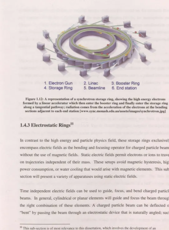
A schematic of a synchrotron is shown in figure 1.12. The synchrotron is not perfectly
circular, but rather a polygonal geometry, whereby the electrons uniformly travel through
the straight sections, which then become accelerated at the bending sections. A linear
accelerator coupled with an electron gun provides the initial injected high energy
electrons.
1. Electron Gun 4. Storage Ring
2. Linac 5. Beamline
3. Booster Ring 6. End station
Figure 1.12: A representation of a synchrotron storage ring, showing the high energy electrons formed by a linear accelerator which then enter the booster ring and finally enter the storage ring
along a tangential pathway; radiation comes from the acceleration of the electrons at the bending sections adjacent to each end station [ www .sync.monash.edu.au/assets/images/synchrotron.jpg]
1.4.3 Electrostatic Rings§§
In contrast to the high energy and particle physics field, these storage rings exclusively
encompass electric fields as the bending and focusing operator for charged particle beams
without the use of magnetic fields. Static electric fields permit electrons or ions to travel
on trajectories independent of their mass. These setups avoid magnetic hysteresis, high
power consumption, or water cooling that would arise with magnetic elements. This
sub-section will present a variety of apparatuses using static electric fields.
Time independent electric fields can be used to guide, focus, and bend charged particle
beams. In general, cylindrical or planar elements will guide and focus the beam through
the right combination of these elements. A charged particle beam can be deflected or
"bent" by passing the beam through an electrostatic device that is naturally angled; such
as hemispherical, cylindrical, or toroidal energy analyzers [for toroid see for example Roy
and Carette (1971), for cylindrical see for example Hughes (1929), for hemisphere see
Chapter 2 of this thesis and Zouros and Benis (2002)]. An appropriate combination of
these electrostatic elements can form a closed path and allow for charged particle storage,
which takes advantage of the t~o dimensional focusing properties of the hemispherical
deflector analyzer, as an example.
Throughout most of charged particle ring history, electrostatic rings have not been
implemented due to the low energy limit of such &-ystems that conflicted with the aims of
the high energy and particle physics community. An exception to this is a pulsed alternate
gradient synchrotron (AGS) that was built in Brookhaven National Laboratory (see
below).
i. Brookhaven Storage Ring
An electrostatic circular ring measuring 141.4 feet in circumference was built in 1954
[Green and Courant (1959)]. A 1.0 MeV Van de Graaff generator supplies the injection
energy for the electrons emitted on a near tangent to the ring and brought on the azimuth
by a pulsed field. The electrons begin to fill the ring for the duration of the inflection
potential pulse. The electrons from the injected beam will begin the storage cycle and
continue to circulate around the ring. Storage could be achieved by weak pulsed magnetic
fields, however, their research group found a number of experimental difficulties with
achieving very precise pulsed B fields. Thus, electric fields were implemented through
the use of static electric potentials applied to stainless steel electrodes. The lens or
"focusing section" consists of unit cells which contain a combination of a half - focusing
lens and a half - defocusing lens. A total of f arty of these unit cells have been
incorporated into the synchrotron ring. The unit cells have been figured with lenses with
an aperture of 0.8 inch in diameter. Electrom circulate within the ring with a revolution
frequency of 7 .0 MHz ( or orbit period of 0.14 µsec). The system has also incorporated
energy is lost to electromagnetic radiation. The AGS at Brookhaven was built to store
electrons, and used for diagnostic tests only [Andersen, Heber and Zajfman (2004)].
ii. ELISA
A racetrack style heavy ion storage ring that encompasses electrostatic elements only,
was built in Denmark in 1997 [Moller (1997), Moller and Pedersen (2001)]. The ELISA
system or electrostatic ion storage ring, Aarhus consists of two 160 degree electrostatic
deflectors, four 10 degree parallel plate deflectors, and four pairs of electrostatic
quadrupoles, as is shown in figure 1.13. The system measures approximately 6.28 meters
in circumference, with an injection energy of - 25 keV, and an orbit time of 2.9 µsec
[protons] and 77 µsec [C-60 ions]. Initially the 160 degree deflectors were 180 degrees,
which was found to give an over-focusing for their system. The 180° hemispherical
deflectors were then changed to the 160° style, which resulted in a well-defined beam.
The 160° ( opposed to 180°) provides a clever setup that incorporates the 10° deflectors to
inject the ke V ion beam directly on the axis (see figure 1.13). In this setup there is no
need to pulse any high voltage storing elements, which is advantageous as AC potentials
will radiate and can induce small amplitude AC signals or "noise" on elements that can
act as perturbations on the storage conditions. However, the injection system (not shown
in diagram) does contain pulsing elements that, although separate from the main storage
ring, results in noise "pick - up" on the elements of the main ring, which has not been
discovered to be deleterious to the stored beam.
The ELISA design has been experimentally copied in Japan with the same racetrack ring style [Tanabea et.al. (2002)]. The group of Tanabea has created their ring with a larger circumference of 8.136 meters, and corresponding higher energy. Instead of protons or C-60 ions inside the ring, the Japanese experiment used
o+
ions at 30 ke V.iii. FLAIR
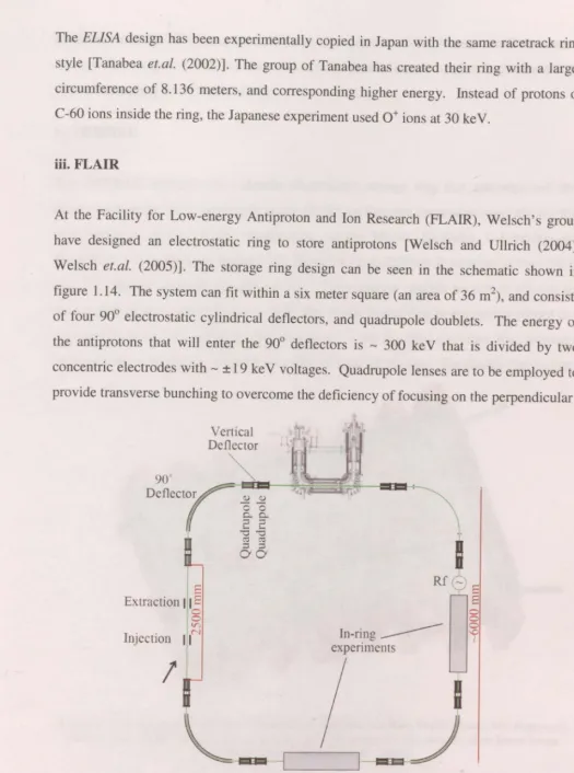
At the Facility for Low-energy Antiproton and Ion Research (FLAIR), Welsch's group have designed an electrostatic ring to store anti protons [Welsch and Ullrich (2004 ), Welsch et.al. (2005)]. The storage ring design can be seen in the schematic shown in figure 1.14. The system can fit within a six meter square (an area of 36 m2
), and consists
of four 90° electrostatic cylindrical deflectors, and quadrupole doublets. The energy of the anti protons that will enter the 90° deflectors is - 300 ke V that is divided by two concentric electrodes with - ± 19 ke V voltages. Quadrupole lenses are to be employed to provide transverse bunching to overcome the deficiency of focusing on the perpendicular
90°
Deflectoy
11
{ -0 -0
6 Extraction 11 E
0 0
V)
. . N
In.1ect1on 11
I
ro ro
;::i ;:::3
0 0
Inring -experiments
Figure 1.14: A schematic diagram of the FLAIR storage ring (see text for details) [Welsch et.al.
direction from the 90° cylindrical deflectors. The system will implement a radiofrequency tube (with voltages < 100 V) that will counteract the innate longitudinal debunching effects (spreading of the beam width).
iv. DESIREE
The DESIREE apparatus is a double electrostatic storage ring that encompassed two electrostatic rings of the same style as the ELISA or Tanabea rings ( discussed above) that was designed, and is under construction, at }he Manne Siegbahn Laboratory and Stockholm University (see figure 1.15) [Rensfelt et.al. (2004)]. It consists of two 9.2 m rings*** with one common straight section. The common straight section is present for the purpose of ion - ion collision studies. The whole double ring instrument is placed in a vacuum chamber and cryogenically cooled to - 10 K. This provides the necessary environment to mimic ion interactions within interstellar plasma. The double ring layout
Figure 1.15: A diagram of DESIREE (Double ElectroStatic Ion Ring ExpEriment), two rings each similar to the ELISA design share a common straight section for the purpose of co-linear beam
collision studies [Rensfelt et.al. (2004)].
offers merged beam tests for both positive and negative ions. The cold environment of
the system provides an ultrahigh vacuum that is ideal for longer lifetimes of the stored
beam.
1.5SUMMARY
Over the previous few decades research groups have addressed challenges in both design
and experiment to maximize the efficiency of their traps. A number of techniques of
trapping and storing of charged particles have been presented. The chapter introduced
apparatuses that confine particles at a single point, which although not identical to this
thesis, provides the concept of behaviors of charged particles within different
electromagnetic field combinations. The point trap concept imparts the notion that
trapping is related to both the type and magnitude of the fields that are present. Storage
rings were also presented showing some of the innovations and theoretical constraints
that will be addressed in detail in the next chapter for the Low Energy Electrostatic
REFERENCES
Abramowitz M., and Stegun I.A. Handbook of Mathematical Functions, Dover publications (1972)
Andersen L.H., Heber 0., and Zajfman D., lour. Phys. B: At. Mol. Opt. Phys., 37 (2004) R57-R88
Bennewitz H.G., and Paul W, Z. Phys., 139 (1954) 489
Bennewitz H.G., Paul W., and Schlier C., Z. Phys., 141 (1955) 6
Bhushan K. G., Pedersen H. B., Altstein N., Heber 0., Rappaport M. L., and Zajfman D.,
Phys.Rev.A,62(2000)012504
Bollinger J. J., Mitchell T. B., Huang X.P., Itano W. M., Tan J. N., Jelenkovic B. M., and Wineland D. J., Phys. Plas., 7 (2000) 7
Brown L.S., and Gabrielse G., Rev. Mod. Phys., 58 (1986) 233 Church D.A., lour. App. Phys. 40 (1969) 3127
Clarke J., van der Werf D. P., Griffiths B., Beddows D. C. S., Charlton M., Telle H. H., and Watkeys P. R., Rev. Sci. Instrum., 77 (2006) 063302
Courant E.D., and Snyder H.S., Ann. Phys. 3 (1958) 1 - 48
deGrassie J. S., and Malmberg J. H., Phys. Rev. Lett., 39 (1977) 1077 Duke P., Synchrotron Radiation, Oxford University Press (2000)
Green G.K. and Courant E.D., Handbuch der Physik, Band XLIV, (Berlin: Springer) p. 319 (1959)
Hasegawa T., Jensen M.J., and Bollinger J. J., Phys. Rev. A, 71 (2005) 023406 Holzscheiter M.H., Charlton M., and Nieto M.M., Phys. Rep. 402 (2004) 1-101
Hughes A.L., Phys. Rev., 34 ( 1929) 284
Jackson, J.D. Classical Electrodynamics, Wiley & Sons Inc. 1998
Jefferts S.R., Monroe C., Bell E.W., and Wineland D.J. Phys. Rev. A 51 3112 Moller S.P., Nucl. Instrum. Methods A, 394 (1997) 281 - 286.
Moller S.P., and Pedersen U.V., Phys. Ser., T92 (2001) 105 - 109
Naaman A., Bhushan K. G., Pedersen H. B., Altstein N., Heber 0., Rappaport M. L., Moalem R., and Zajfman D., l. Chem. Phys., 113 (2000) 4662
Paul W., Rev. Mod. Phys., 62 No. 3 (1990)
Pedersen H. B., Strasser D., Ring S., Heber 0., Rappaport M. L., Rudich Y., Sagi I., and Zajfman D., Phys. Rev. Lett. 87 (2001) Ar. Num. 055001


![Figure 1.11: A schematic diagram of the Paul-Type Racetrack Storage Ring [Church (1969)]](https://thumb-us.123doks.com/thumbv2/123dok_us/1502902.1183965/38.627.8.558.24.741/figure-schematic-diagram-paul-type-racetrack-storage-church.webp)