Design and Analysis of High Density
Polyethylene Fuel Tank for Heavy Vechicle
Masilamani.R1, P.Suresh2, P.Tamilazhagan3, N.Madhavan4, S.Ponnuswamy5
Assistant Professor, Department of Mechanical Engineering, Karpagam College of Engineering (Autonomous),
Coimbatore, Tamil Nadu, India. 1
Professor, Department of Mechanical Engineering, Karpagam College of Engineering (Autonomous), Coimbatore,
Tamil Nadu, India. 2
UG Scholar, Department of Mechanical Engineering, Karpagam College of Engineering (Autonomous), Coimbatore,
Tamil Nadu, India. 3,4,5
ABSTRACT: Plastic fuel tanks and systems are designed to offer environment-friendly, cost-effective, lightweight, and safe solutions to the automotive industry.The objective of the present work is to design and numerically examine the impact strength and develop a modular prototype using high density polyethylene plastic, which is a strong and lightweight material, enable manufacturers to substantially reduce the overall weight of their vehicles & making the vehicles more fuel efficient. Plastic fuel tanks also allow for increased safety in the event of crash. Unlike metal fuel tanks, many can bend & flatten, rather than tearing, rupturing & spilling gasoline, thereby safely eliminating fuel leakage as a cause of a fire or explosion.
KEYWORDS: Plastic Tank, Polyethylene Plastic, Increased Safety, Fuel Leakage.
I.INTRODUCTION
A fuel tank is a safe container for flammable fluids. Though any storage tank for fuel may be so called, the term is typically applied to part of an engine system in which the fuel is stored and propelled or released into an engine. Fuel tanks range in size and intricacy from the small plastic tank of a butane lighter to the multi-chambered cryogenic Space Shuttle external tank. Plastic has become the material of choice for fuel tank manufacturers. In Europe, 90% of all produced fuel tanks are made of plastic. In the United States, over 75% of automotive fuel tanks are multilayer plastic fuel tanks. Plastic fuel tanks are made of high-density polyethylene (HDPE), which is a strong and lightweight material, enabling manufacturers to considerably reduce the overall weight of their vehicles and making vehicles more fuel-efficient. Plastic fuel tanks also allow for increased safety in the event of a crash. Unlike metal fuel tanks, many can bend and flatten, rather than tearing, rupturing and spilling gasoline, thereby safely eliminating fuel leakage as a cause of a fire or explosion. Plastic can be molded around specific parts. In addition, plastic fuel tanks are corrosion resistant, whereas steel tanks require stainless steel to provide a similar level of corrosion resistance, which also means a greater cost.
II. INITIAL TANK ANALYSIS
fuel tanks for an typical of 171,000 passenger G vans per year in addition to just about 3.7 million fuel tanks for other model vehicles. On the other hand, the multi-layer plastic tank is used on the low production cutaway van, requiring a production volume of 20,000 tanks per year. Ideally, made of steel. Earlier versions of the plastic fuel tank used fluorination to reduce fuel permeation. With the invention of the co extrusion blow molding process by Krupp-Kautex, plastic fuel tanks are now more permeation-resistant than their predecessors. Multi-layer plastic tanks are now better able to meet automobile emissions requirements as guided by the EPA and CARB than previous monolayer tanks.Despite the limitations of life cycle design, which were identified in this demonstration, the project team gained some important insights regarding the ecological contour of the steel and HDPE fuel tank systems. In addition, the analyses of feat, cost, and policy issues surrounding fuel tank design were valuable for all team members. One attribute of life cycle design is that it provides a framework for identifying and resolving critical design issues. This project provided an opportunity for product development team members that have different functional responsibilities to address the broad scope and complexity of life cycle design issues. This study expanded the scope of analysis beyond the system boundaries used previously by GM for fuel tank design. The overall premise of life cycle design is that a more comprehensive analysis will ultimately create more economically and ecologically sustainable products. This hypothesis will be tested as more corporations begin to implement key elements of life cycle design and organization.
III. PROBLEM STATEMENT
One plastic tank have the ability to meet packaging constraints with complex shapes, & design engineers have greater flexibility in the truck design & styling without having to worry about fitting the gas tank. The plastic tank could virtually be made to fit whatever cavities are left by the design. Plastic swells with constant exposure to organic liquids & vapor, thus making the joints very critical in the event of repairing the tank hardware.
IV. MATERIAL TESTING
Plastic tanks have the ability to meet packaging constraints with complex shapes, and design engineers have greater elasticity in the car design and styling without having to worry about fitting the gas tank. The plastic tank could virtually be made to fit whatever cavities are left by the design. Other attachments to and within the plastic tank require casketed mechanical joints. However, plastic swells with constant exposure to organic liquids and vapor. However, Cadillac claims that although their plastic tanks allow design elasticity with increased safety, they do not achieve any weight savings over steel tanks. These two examples seem to gainsay .The general view that plastic's weight advantage increases with the size of the tank. On the other hand, the new permeability requirement is expected to shrink the weight advantage of plastics.
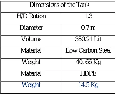
Table IV: Dimensions of the tank Dimensions of the Tank
H/D Ration 1.3
Diameter 0.7 m
Volume 350.21 Lit
Material Low Carbon Steel
Weight 40. 66 Kg
Material HDPE
Figure IV: Fuel Tank
V. SOFTWARE RESULTS OF DESIGN
V.I. Viewing Results
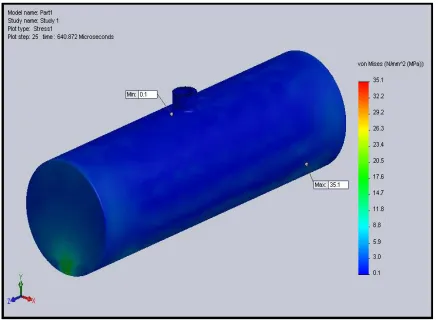
The user can view contour plots of stress, displacement, and strains at the instants that the program stored results at all locations. User can also graph response at the pre-selected locations (vertices and reference points) at the specified resolution. For example, suppose that you set the observation time to 10 microseconds, the number of instants to save all results to 30, and the number of graph points per plot period to 10.
V.II. Integration Points
Assuming that the number of actual solution steps, internally decided by the solver, is equal to or greater than 300, then user can generate fringe plots at 10/30 microsecond intervals and each response graph will have 30x10=300 graph points. The instants of time at which the response is saved may not be exactly uniform. The program uses results from the closest instant at which the solution is available. Due to the very small time increments that the program internally uses due to solution stability requirements, the response is practically saved at uniform intervals.
Plastic tank
Steel Tank
Figure V.II. 2(c): Von-Mises Stress
VI.CORROSION
Corrosion is a well-known concern on both the inside and outside surfaces of tanks. The outside surfaces and supporting structure are bare to road chemicals, salt, mud, and gravel. The corrosion issue is critical with zinc-coated products that swap terne plate because of their sacrificial nature, which puts an even higher demand on the quality of the barrier film for both inside and outside surfaces. In contrast, the plastic gas tanks are inert to the corrosive environments inside and outside the tank.
VII.FUTURE WORK
Drop Test Simulation for Steel Tank
Drop Test Simulation for HDPE tank
Design Improvement
VIII.CONCLUSION
In this analysis, we have analysis the design and numerically examine the impact strength and developed a modular prototype using high density polyethylene plastic (HDPE),it is a strong and lightweight material thus enable manufacturers to substantially reduce the overall weight of their vehicles & making the vehicles more fuel efficient. It is also environment-friendly and cost-effective. It is safely eliminating fuel leakage.
REFERENCES
[1] Southwest Research Institute Dr.NabihBedewi (2011) “Fire Exposure, Impact Tests, Finite Element Modeling of Plastic Fuel Tanks”, Vol II [2] Bundy International, "Fuel Supply Systems for a Healthier Environment", ed. Michael Scarlett, Automotive Technology International '94, pp.
37-40.
[3] Delphi VII Forecast and Analysis of the North American Automotive Industry (Ann Arbor, MI: Office for the Study of Automotive
Transportation, University of Michigan Transportation Research Institute, 1994), pp. 71-75.
[4] Timothy T. Maxwell and Jesse C. Jones, Alternative Fuels: Emissions, Economics and Performance (Warrendale, PA: Society of Automotive Engineers, 1995), pp. 29-42.
[5] Lu Y.(2010) et. Al ‘ Numerical& experimental investigation on dynamic load of a heavy duty vehicle’, Applied mathematical modeling, 2698-2710, Inc.
[6] Peter J.Alvarado (2010) ‘ steelvs plastic’: The competition for light vehicle fuel tanks, SAE International Vol.2004-1-538.