ABSTRACT
WHITE, CHARLES EDWARD CAUTHEN. Manufacturing and Structural Characterization of Flexible and Dual-Matrix Deployable Composites for Space Application. (Under the direction of Dr. Mark Pankow).
Manufacturing and Structural Characterization of Flexible and Dual-Matrix Deployable Composites for Space Application
by
Charles Edward Cauthen White
A thesis submitted to the Graduate Faculty of North Carolina State University
in partial fulfillment of the requirements for the degree of
Master of Science
Aerospace Engineering
Raleigh, North Carolina 2016
APPROVED BY:
_______________________________ _______________________________
Dr. Scott Ferguson Dr. Jeffrey Eischen
_______________________________ Dr. Mark Pankow
DEDICATION
BIOGRAPHY
ACKNOWLEDGMENTS
Most of all I want to express my gratitude to my advising professor Dr. Mark Pankow for allowing me to work in the BLAST Lab and for providing supplies for my composite fabrication. I appreciate how I was allowed to determine my own research topic and for your guidance as I worked through it all.
Thank you to Dr. Scott Ferguson and Dr. Jeffery Eischen for serving on my defense committee. A special thanks to several faculty and staff who without their assistance I would not have been able to complete my research. Steve Cameron in the MAE machine shop fabricated several complex molds and fixtures which were used in this research. Gary Lofton also fabricated various fixtures and cut many samples using the water jet. Gary also sponsored me through two semesters as a TA in the senior design machine shop, as a by-product I was allowed access to tools and machines which I was able to use for my own research. Dr. James Kribs presented a helping hand countless times in his offer of laboratory resources, especially access to his Instron loading frame. Without the help of these people and the guidance of all my professors I would not have been able to complete such interesting research in such a positive environment.
A special thanks as well to Dr. Juan ‘Johnny’ Fernandez at NASA Langley Research Center in Hampton, VA for sponsoring me through two internships working on deployable booms. Thank you for the opportunity to observe research at a professional level and for passing along your knowledge of fabrication and testing of deployable ultra-thin fiber composite structures.
Also I want to thank the students working in the BLAST lab for enduring my random shenanigans and spontaneous acts of singing and dancing. Thank you Narender for countless times being my buddy while I sat in front of the Instron and thank you Alex for fabricating some composites alongside me.
TABLE OF CONTENTS
LIST OF TABLES ... vii
LIST OF FIGURES ... viii
Chapter 1 – Introduction ... 1
1.1 – Background ... 1
1.2 – Research Objectives ... 7
1.3 – Research Questions ... 7
1.4 – Thesis Outline ... 8
Chapter 2 – HSC CubeSat Boom ... 9
2.1 – HSC Familiarity ... 9
2.2 – Boom Fabrication... 10
2.3 – Conclusion ... 19
Chapter 3 – Dual-Matrix Fabrication ... 20
3.1 – A note on matrix ... 20
3.2 – Current dual-matrix methods: ... 21
3.3 – Wet Lay-up Development ... 24
3.4 – Origami Fold Techniques ... 32
3.5 - Conclusion ... 36
Chapter 4 – Characterization ... 37
4.1 – Microstructure ... 37
4.2 – Testing Approach of HSC ... 39
4.3 – Modified Platen Test ... 42
4.5 – Simple Joint in Bending ... 47
4.6 – Simple Joint in Tension ... 66
4.7 – CubeSat Boom ... 75
Chapter 5 - Finite Element Analysis ... 79
5.1 – Material Properties and Modeling Technique ... 79
5.2 – Simple Joint in Bending ... 80
5.3 – CubeSat boom ... 84
5.4 – Conclusion ... 88
Chapter 6 – Conclusions ... 89
6.1 – HSC CubeSat Boom Development ... 89
6.2 – Dual Matrix Feasibility ... 89
6.3 – Experimental Test Methods ... 90
6.4 – FEA Correlation Accuracy ... 91
REFERENCES ... 93
APPENDICES ... 96
LIST OF TABLES
Table 1. Thickness of Differently Sourced Carbon Fibers ... 13
Table 2. Properties of Various Matrix Systems ... 24
Table 3. Common Fiber Volume Fractions in Different Processes [20] ... 37
Table 4. Fiber Volume Fraction of CFRS ... 38
Table 5. D11 Bending Stiffness of Epoxy Infused Coupons ... 52
Table 6. Modulus of 0-90o epoxy coupons ... 55
Table 7. Modulus of 45o Epoxy coupons ... 56
Table 8. Empirical Bending Modulus and D11 Stiffness of 0-90o silicone Coupons with Aluminum Tabs ... 57
Table 9. Empirical Bending Modulus and D11 Stiffness of ±45o silicone Coupons with Aluminum Tabs ... 58
Table 10. Empirical Bending Modulus and D11 Stiffness of 0-90o Silicone Coupons with Carbon Epoxy Tabs... 60
Table 11. Empirical Bending Modulus and D11 Stiffness of ±45o Silicone Coupons with Carbon Epoxy Tabs... 61
Table 12. Effective Structural Modulus of 0-90o Tensile Specimens ... 68
Table 13. Strain Values (sample 2) Corresponding to Limit of Linear Region in ±45o Samples ... 70
LIST OF FIGURES
Figure 1. Folding of Closed Form Composite Tape Spring Hinge [3] ... 2
Figure 2. Spring Hinge made from Curved Composite Shells [5] ... 3
Figure 3. Omega Shaped Boom by DLR [6] ... 3
Figure 4. Carbon Fiber Reinforced Silicone (CFRS) Reflecting Surface [8] ... 4
Figure 5. Folding Sequence of Dual-Matrix CubeSat Antenna [13] ... 5
Figure 6. Modified Origami Flasher Model Solar Array Concept [14] ... 6
Figure 7. Half Boom Aluminum Molds ... 10
Figure 8. Half Boom Vacuum Bag Fabrication ... 11
Figure 9. Tab Trimming Using Machined Straight Edge with Lip ... 11
Figure 10. Cracked Pre-Preg boom ... 12
Figure 11. 3K verse 1K Woven Fiber Crimping due to Individual Tow Thickness ... 13
Figure 12. Twisted Half Boom Due to Thermal Deformation of a Stitched Fabric ... 14
Figure 13. Oppositely Complementary Vector Ply Bonded Whole Boom ... 15
Figure 14. Flattened and Rolled Whole 1K Boom ... 16
Figure 15. Tab De-Bonding of Whole Boom ... 16
Figure 16. Silicone Mold Forming for Whole Boom Fabrication ... 17
Figure 17. Single Cure Whole Boom Fabrication ... 17
Figure 18. Silicone Plug Removal ... 18
Figure 19. Silicone Plug Method using 4ft Long Teflon Covered High Density Foam Mold 18 Figure 20. 12 Foot Boom Supporting its own Weight ... 19
Figure 21. Flexible Dual-Matrix Diagram [20] ... 21
Figure 22. Miura fold of dual matrix laminate [18] ... 22
Figure 23. Occluded Single Ply For Bounding Material Test ... 24
Figure 24. Successful Single Ply Silicone Infused boundary ... 26
Figure 25. Removal of Excess Silicone Prior to Bounding Material Removal ... 26
Figure 26. Multi-Ply Bounding on Top and Bottom ... 27
Figure 28. Surface Finish of CFRS in Open Air vs. Vacuum Bagging with Peel Ply ... 29
Figure 29. Pitted Surface Finish due to Breather Layer Compaction ... 30
Figure 30. Second Attempt Glass Fiber Assisted Pressure Intensifier ... 30
Figure 31. Carbon Fiber Diffuser Assisted Pressure Intensifier ... 31
Figure 32. Acceptable Surface Finish of Hinged Panel from CF Pressure Intensifier ... 31
Figure 33. Blintz Origami Fold ... 32
Figure 34. Miura Folding Sheet ... 33
Figure 35. Basic Origami Flasher Model Dual-Matrix Demonstration ... 34
Figure 36. Fold pattern of origami solar array concept [8] ... 34
Figure 37. Bounding and Infusion of Dual-matrix Flasher Array ... 35
Figure 38. Origami Flasher Concept - Storage and Deployment ... 36
Figure 39. Computed Tomography (CT) Scan of 4 Ply CFRS ... 39
Figure 40. Four-Point Bend Fixture and F.B.D. [24]... 41
Figure 41. Modified Platen Test and F.B.D. [11] ... 41
Figure 42. Dimensioning and FBD of Modified Platen Test ... 42
Figure 43. Moment vs. Curvature Relation - Empirical Bending Stiffness D11 ... 44
Figure 44. Speckle Pattern of Bending Specimen ... 47
Figure 45. Tab Bonding of Epoxy Infused Coupons ... 48
Figure 46. Painted Bending Coupons (left: epoxy, middle: silicone, right: silicone with carbon tab) ... 48
Figure 47. '2+2' Ply verse 4 Ply Silicone Hinge and Secondary Epoxy Infusion Process ... 49
Figure 48. Pre-Buckled Installation ... 50
Figure 49. DIC 3D Strain and 2D Curvature Setup for Bending Test ... 50
Figure 50. Normalized Moment verse Fold Angle of Epoxy Infused Coupons ... 51
Figure 51. Curve Fit Overlay to Verify Curvature Measurement ... 51
Figure 52. D11 Stiffness and ‘Best-Fit’ of Epoxy Infused Coupons According to DIC Measurements ... 52
Figure 53. Strain Variation According to Different Measurement Techniques... 53
Figure 55. Stress vs. Strain of 0-90o Specimen According to Different Strain Measurements
... 55
Figure 56. Curved Geometry of 0-90o Silicone Coupons with Aluminum Tabs ... 57
Figure 57. Curved Geometry of ±45o Silicone Coupons with Aluminum Tabs ... 58
Figure 58. Curved Geometry of 0-90o Silicone Coupons with Carbon Epoxy Tabs ... 60
Figure 59. Curved Geometry of ±45o Silicone Coupons with Carbon Epoxy Tabs ... 61
Figure 60. Loading of Silicone Coupons ... 62
Figure 61. Discrepancy Between Aluminum vs. Carbon Tab Specimen Strains (0-90o Fiber) ... 63
Figure 62. Curvature Response of 4P Silicone Specimens ... 64
Figure 63. Curvature Response of ‘2+2’P Silicone Coupons ... 65
Figure 64. Load verse Displacement of 4 ply specimens ... 66
Figure 65. Truncated Stress Strain Loading of 0-90o Specimens in Tension ... 68
Figure 66. Strain Regions of Necking Samples ... 69
Figure 67. Global Strain (±45o sample 2) Comparison over Entire Loading Range ... 70
Figure 68. Global Strain (±45o sample 2) Comparison over Linear loading Range ... 70
Figure 69. Deformation of ±45o 0.4inch Jointed Tensile Specimen ... 71
Figure 70. Initial Strain Developed in ±45o 0.4inch Jointed Tensile Specimen ... 71
Figure 71. Deformation of ±45o 0.8inch Jointed Tensile Specimen ... 72
Figure 72. Initial Strain Developed in ±45o 0.8inch Jointed Tensile Specimen ... 73
Figure 73. Load Deflection Trend due to ±45o Fiber Re-orientation ... 74
Figure 74. Loading and Constraints for Half Boom Flattening ... 75
Figure 75. Represented Average Loading and Unloading of Half Boom ... 76
Figure 76. Profile View Recorded through 45o Mirror ... 77
Figure 77. Flattening Profile of Half Boom ... 77
Figure 78. Represented Average Loading and Unloading of a ±45o Whole Boom ... 78
Figure 79. Variation of Poisson’s Ratio as Function of Weave Angle [23] ... 79
Figure 80. FEA Bending Analysis Assembly and Mesh ... 80
Figure 82. Effects of Shear Modulus on Bending Stiffness... 81
Figure 83. Poisson’s Ratio Effect on FEA Bending Force 45o Properties... 82
Figure 84. Poisson’s Ratio Effect on FEA Bending Force 0o Properties... 82
Figure 85. Epoxy Infused Specimens Measured vs. FEA Bending Stiffness ... 83
Figure 86. Assembly and Boundary Conditions of the Half Boom Model ... 84
Figure 87. Half Boom Mesh with S4R5 Elements ... 85
Figure 88. FEA vs Actual Half Boom Wing Deformation ... 85
Figure 89. Visualization of FEA Half Boom Flattening Analysis ... 86
Figure 90. Effects of Poisson’s Ratio on Bending Analysis 45o Properties ... 86
Figure 91. Effects of Poisson’s Ratio on Bending Analysis 0o Properties ... 87
Chapter 1 – Introduction
1.1 – Background
Space structures are volumetrically limited by the cargo capacity of their launch vehicle. Satellites, antenna, and solar arrays which deploy to many times larger than their launch vehicle require complex packaging or secondary assembly once in orbit. Historically this has been solved by mechanical hinges or modular designs. For efficiency, it is advantageous to launch in the smallest packaging volume relative to the deployed size. Engineering research into structural packaging efficiencies and deployment methods has become crucial to send larger structures into and beyond orbit without relying on larger and larger launch vehicles. The focus of this study will investigate fiber reinforced composite structures capable of large deformation and strain, thus enabling structures to change shape, supporting next generation space deployables.
Static loading and folding of thin composite tape springs to measure the bending stiffness of a hinge has been modeled using FEA software and verified through testing physical prototypes [2]. Further investigations have constrained two oppositely opposing tape springs in parallel to act similar to a closed form cross section; creating a hinge with increased stiffness and torsional rigidity [1]. Other variations have also shown increased stiffness with good repeatability in accurate deployments. Cutting two oval sections from a closed form tube allows flattening and folding of the slotted region with the remaining material acting as two parallel tape springs, Figure 1 [3]. Repeated deployment of this continuous fiber structure showed little to no hysteresis in shape or stiffness [4].
FIGURE 1.FOLDING OF CLOSED FORM COMPOSITE TAPE SPRING HINGE [3]
FIGURE 2.SPRING HINGE MADE FROM CURVED COMPOSITE SHELLS [5]
Another HSC concept developed by German aerospace company DLR was their design for a deployable boom which could tension a set of solar sails, Figure 3. These booms used ultra-thin laminates to form a closed cross section capable of providing adequate bending and torsional stiffness in the deployed state, could also be pressed flat and then rolled around a central hub for storage and launch [6]. Strain levels of the outer surface are developed both when flattening and rolling but are kept within a tolerable range due to the ultra-thin, 0.1mm, shell thickness. The maximum curvature or minimum radius that can be achieved by HSC lamina is determined by the tensile strain limit of the material seen on the exterior curved face.
FIGURE 3.OMEGA SHAPED BOOM BY DLR[6]
impulse deformations to occur without overstressing or cracking the matrix, which in part preserved the fiber integrity [7]. Further application was seen in the skin design of a morphing wing where large deformations and relatively small curvatures were attained through use of a carbon fiber laminate infused with a semi rigid polyurethane matrix [8]. The fiber reinforced wing skins were allowed to conform to these large bending deformations without failure because the matrix remained in its elastic region and transferred little stress to the fibers.
Applications in the space industry have also investigated high straining, low modulus matrix materials through carbon fiber reinforced silicone (CFRS) laminates but have yet to fly on any mission. In the design of a large deployable reflector (LDR) receiving dish for communication satellites a novel silicone infused flexible carbon fiber lamina was investigated, Figure 4 [9]. The shell membrane reflecting surface of this satellite needed to exhibit, under certain tensile loading conditions, adequate bending stiffness to hold a double curved geometry but remain pliable enough to fold like an umbrella. This behavior was successfully achieved with high dimensional stability through use of a flexible CFRS membrane.
FIGURE 4.CARBON FIBER REINFORCED SILICONE (CFRS)REFLECTING SURFACE [8]
stiffness due to cyclic loading [11]. Additional research has predicted the extent of fiber failures associated with large deformations [12]. As seen in many of these investigations, characterization of hyper elastic matrices differ from standard CLT just as ultra-thin HSC lamina also differ from theory.
Dual-matrix composites are then another derivation from HSC and hyper elastic composite work. By applying two distinctly different stiffness matrices, one of which is hyper elastic, into a single laminate it is possible to create regions which can be bent or folded to very small radius of curvature. In applying the hyper elastic matrix to precise areas within the laminate it is possible to create detailed architectures of spring hinges, Figure 5. These regions were created within a continuous fiber structure by locally infusing silicone into a larger and stiffer laminate to create an antenna concept for CubeSat satellites [13]. Narrow regions extending the length and spaced radially about the cone shaped receiver were infused with a UV cured silicone rubber. The silicone regions allowed the receiver to be folded, flattened and stored for launch.
A subset of engineering which has emerged in recent years and which dual-matrix laminates have application is in the utilization of origami fold techniques. Origami principals are inspiring efficient packaging and helping to create semi rigid structures that are magnitudes stiffer than their construction material. The art of origami uses thin paper which remains pliable when doubled or tripled in thickness. As thickness increases it becomes necessary to account for the expanded volume associated with each fold region. The hinge and rigid regions of thick origami then need to be adjusted for the expanding fold volume. This folding problem was investigated through mathematical development of a ‘flasher-model’ solar array [14]. One design consideration for supporting solar cell collectors, was the need for the non-folding regions to remain rigid or semi rigid. This is to prevent the cells attached to non-folding regions from breaking or cracking during deployment. This additional consideration is known as rigid foldable origami. A 1/20th scale model of this array was constructed using demonstrative materials, Figure 6. Material selection for flight hardware is one of the next steps in implementing this technology and also an area that flexible and dual-matrix composites could support.
It has been shown that many applications using HSC and hyper elastic matrices provide opportunity for deployment without the need of mechanical hinges or moving parts. Dual-matrix composites have also shown alternative methods for packaging of complex structures using origami fold techniques. To implement these low mass, high stiffness and dimensionally stable materials into next generation space structures continued research into manufacturing and material characterization is required before wide scale implementations can be made.
1.2 – Research Objectives
Understanding of thin HSC will be made through fabrication and testing of a deployable boom for CubeSat missions. Novel infusion methods for dual-matrix laminates will also be expanded as non-proprietary and out of autoclave methods are developed for accurately infusing a complex dual-matrix architecture within a larger laminate. Dual-matrix structures will then be combined with origami folding patterns to create deployable structures. Macro-mechanical characterization of flexible and dual-matrix laminates will be experimentally tested through a modified platen test to measure the bending stiffness of small coupon specimens as they are conformed to a small radius of curvature. The flattening stiffness of the HSC CubeSat boom will be tested and along with the bending test data, correlation will be started using finite element analysis (FEA) modeling through available ABAQUS software.
1.3 – Research Questions
1.4 – Thesis Outline
Chapter 2 – HSC CubeSat Boom
Manufacturing of a high strain composite deployable boom scaled for CubeSat incorporation is developed here to flatten and roll about a cylindrical storage hub. Initial fabrication used two separate cure cycles to bond independently cured halves into a closed cross section. Further development allowed cure of a whole boom in a single cure through use of a manufacturing plug. Finally using ultra-thin spread tow pre-preg fabrics a 12 foot long boom was fabricated in a single cure.
2.1 – HSC Familiarity
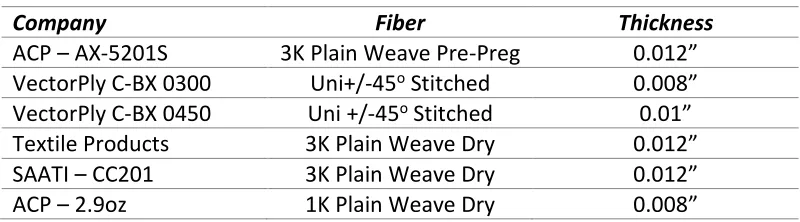
The design of a deployable carbon fiber boom for non-gossamer applications was developed, fabricated and tested for CubeSat scale satellites. This work was prompted by a deployable boom design from DLR [6] intended to be used as the tensioning structure for a solar sail, Figure 3. Each half of the boom was manufactured independently, in the deployed state, and then bonded together in a second cure cycle to form the closed cross section. This open cross section is the state of lowest energy and causes the stored boom to unroll and open, aiding in deployment. Their design measured almost 46 feet in length, was 5.9 inches wide and had a deployed cross section height of 4.33 inches. Each half was 0.0039 inches thick, resulting in a flattened height of 0.00787 inches while the width extended to 8.2 inches [15, 6]. Complete scaling of this boom was however not possible due to the limits of shell thickness. For a CubeSat scale mission where the flattened width is 1.57 inches the double laminate thickness would scale to 0.0015 inches, which is 2 to 3 times the thickness of an individual graphite fiber. Due to this unrealistic scaling, the laminate thickness would be fabricated as thin as possible from available materials while the width and height were scaled according to ideal dimensions [16].
longitudinally around a 2 inch cylindrical hub, similar to what would be seen during storage of actual flight hardware.
2.2 – Boom Fabrication
Similar to the design by DLR, initial fabrication methods required the two halves to be cured independently and then bonded together in a second cure cycle. Positive and negative molds were CNC (computer numerical control) machined from aluminum to be used in conjunction as a compression mold for pre-preg fibers or individually in vacuum bagging a wet lay-up. A total of three sets of 12” long molds were fabricated; attaching them to a base plate and aligning them in series created a 36” long mold which could be used to fabricate longer booms, Figure 7.
FIGURE 7.HALF BOOM ALUMINUM MOLDS
cut to size after curing to provide a clean edge. A straight edge used to trim the tabs to size was machined with a lip that fit over the edge of the molds to ensure an exact tab width, Figure 9.
FIGURE 8.HALF BOOM VACUUM BAG FABRICATION
First inquiry was to use a pre-preg fabric, these are desirable in aerospace design as they maintain a predictable and consistently high fiber volume fraction. A pre-preg 3K fabric advertised to be 0.012 inch thick was donated from ACP Composites. The 3K indication represents three-thousand filaments in the individual tows, this size of fabric is the most widely available and least expensive but is not the absolute thinnest. The high fiber volume fraction also leads to a stiffer laminate and after curing a ±45o fiber orientated boom, failure was seen along the individual weave lines due to the stiffness and relatively large thickness to bending ratio, Figure 10.
FIGURE 10.CRACKED PRE-PREG BOOM
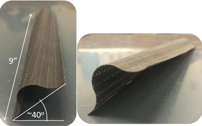
TABLE 1. THICKNESS OF DIFFERENTLY SOURCED CARBON FIBERS
Company Fiber Thickness
ACP – AX-5201S 3K Plain Weave Pre-Preg 0.012”
VectorPly C-BX 0300 Uni+/-45o Stitched 0.008”
VectorPly C-BX 0450 Uni +/-45o Stitched 0.01”
Textile Products 3K Plain Weave Dry 0.012”
SAATI – CC201 3K Plain Weave Dry 0.012”
ACP – 2.9oz 1K Plain Weave Dry 0.008”
The first fabric to use a wet ley-up technique was a 3K plain weave from Textile Products. Examination of a cured half boom showed that flattening could occur without failure when manufactured in a ±45o fiber orientation. However, the large stiffness and compound curvature of flattening and rolling about a 2inch diameter hub caused fractures to develop along the individual weave lines, as seen in the pre-preg boom. An inherent feature of woven fabrics is the out of plain movement and crimping of individual tows as they cross over each other, Figure 11. Stress concentrations of this crimping can lead to failure along the weave lines in such HSC laminates as these and a thinner ply was determined necessary.
FIGURE 11.3K VERSE 1KWOVEN FIBER CRIMPING DUE TO INDIVIDUAL TOW THICKNESS
Alternate fabrics were also simultaneously sourced through donations from VectorPly. The double bias C-BX 0300 and 0450 laminates come manufactured in ±45o stitched fiber orientation. Stitched or knit fabrics, also referred to as a double bias, stack separate layers of unidirectional fibers at different orientations before stitching them together. The 45o orientation used here effectively created a two layer +45o/-45o unidirectional laminate. By stitching the layers instead of weaving them fiber crimping is avoided and a thinner laminate with a higher fiber volume fraction can be achieved. While the un-crimped laminate is desirable, when using only a single layer for each half boom, thermal coupling due to asymmetric fiber orientations become a concern. This was seen when introducing a half boom to a thermal gradient of as little as 20oF, causing them to twist about their longitudinal axis, Figure 12.
FIGURE 12.TWISTED HALF BOOM DUE TO THERMAL DEFORMATION OF A STITCHED FABRIC
The two oppositely opposing fiber orientation half booms were therefore bonded together before introducing a thermal gradient, Figure 13.
FIGURE 13.OPPOSITELY COMPLEMENTARY VECTOR PLY BONDED WHOLE BOOM
To form a closed cross section the tabs of two half booms were bonded together using the same resin system used for infusion. Careful application of resin was lightly applied to the tab region of the first half boom before placing the half into a negative mold. A light application of resin was then applied to the tabs of the second half boom and this half was aligned and placed on top of the first. To ensure alignment of the cross section a second negative mold was placed on top of the matched halves and the edges of the two molds aligned with clamps. The second mold also provided pressure to the bond. After the bond region was cured the tabs were trimmed to the appropriate width using the straight edge template.
FIGURE 14.FLATTENED AND ROLLED WHOLE 1KBOOM
It is assumed however that internal stresses did inherently develop from the displacement constraint. The stiffer VectorPly 0450 asymmetric boom performed poorly when subject to the compound curvature of the cylindrical hub. In areas where the tab bond was weak the two halves would pop apart, unzipping the bond, Figure 15. This popping and unzipping could also be instigated with minimal effort in the other two booms by prying the halves apart with a razor blade. Repeated flattening and rolling of these booms showed decent damage tolerance to the fibers but exposed the bonded tabs to be an area of weakness.
FIGURE 15.TAB DE-BONDING OF WHOLE BOOM
used to manufacture the closed cross section. The plug was made by pouring a two-part silicone rubber into the cavity made between two negative molds, Figure 16. The length of this plug was limited to the length of negative molds which were 12 inches.
FIGURE 16.SILICONE MOLD FORMING FOR WHOLE BOOM FABRICATION
The plug was then used to lay-up both sides of the boom simultaneously while the entire laminate was vacuum bagged, Figure 17.
FIGURE 17.SINGLE CURE WHOLE BOOM FABRICATION
FIGURE 18.SILICONE PLUG REMOVAL
At NASA Langley Research Center in Hampton, VA the plug method manufacturing was improved upon by using a spread-tow woven carbon measuring 0.004 inches thick and infused with an out-gassed approved resin film. Six molds designed to connect linearly, as the smaller aluminum molds had, were CNC machined at 4 foot lengths from a high density foam. The molds were then coated in a Teflon sticker to provide a tooling surface and a silicone plug was poured. Cured under vacuum at elevated temperature for several hours in an oven, 4 foot long booms were manufactured to test the process and performance of the new material, Figure 19. After curing, the tabs were cut to their appropriate width using a precision straight edge.
The molds were aligned using two rods which fit into channels that had been cut on the underside of the mold. Two sets of three molds were aligned and coated with a Teflon sticker to provide a continuous 12 foot tooling surface and a 12 foot silicone plug was poured. The same vacuum bagging and lay-up as the 4 foot boom was repeated here and a 12 foot section cured in an autoclave was successfully manufactured in a single cure cycle, Figure 20.
FIGURE 20.12FOOT BOOM SUPPORTING ITS OWN WEIGHT
After several cure cycles the molds began to warp and periodically the Teflon sticker coating would need to be replaced. The design of 6 molds would allow for a 24 foot boom to manufacture if available autoclave or oven could be sourced. The tooling life of these molds could also be extended if fabricated from a metal or higher quality foam.
2.3 – Conclusion
Chapter 3 – Dual-Matrix Fabrication
The manufacturing of a dual-matrix laminate is developed here to enable spring like hinge folding at regions locally infused with a hyper elastic silicone rubber. Incorporated hinges are then applied in a more complex architecture and using origami folding techniques allow large laminates to be efficiently packaged and stored for launch.
3.1 – A note on matrix
With any payload launched into space, hardware and materials must be outgassed approved so not to contaminate other possibly sensitive payloads from particulates which may form in a vacuum. This leads to the first step in developing dual-matrix and flexible composites for space application, outgas approved materials. Additionally, it is necessary to choose a system able to be accurately manufactured into the desired architecture. However, for this study only the second consideration will be observed and non-outgas approved materials will be examined for their manufacturability and structural performance. Once a suitable hyper elastic matrix and manufacturing method is determined a similar outgas approved system could be implemented.
The polyurethane elastomer RP6442 matrix by Huntsman used in the development of an impact resistant laminate had a modulus of elasticity given around 1000 PSI [17]. An elastomeric resin developed by L’Garde had a tensile modulus measured between 700 to 1000 PSI [18]. This same silicone rubber matrix was later tested and the elastic modulus was given as 435 PSI [19]. L’Garde later produced this silicone rubber for testing and the initial elastic modulus was given as 145 PSI [12]. The CF19-2615 silicone by Nusil was used in the folding of composite laminates and gave an elasticity of 116 PSI and a strain at failure equal to 100% [11]. Lastly, the LOCTITE 5055 UV curing silicone used to create hinges for the wideband CubeSat antenna had a modulus of 290 PSI [13].
elongation before break values will be as high as possible. Primary matrix systems should be similar to matrices used in high stiffness structural applications where Young's modulus is in the 0.4 to 0.6 MSI range [20]. Using this ratio of low to high modulus in bordering matrix systems will enable the hinge or spring response within a continuous fiber laminate.
3.2 – Current dual-matrix methods:
To create a spring hinge or implement origami fold techniques it is necessary to create a boundary region between the two different matrix systems. Various infusion methods of the primary stiff matrix are well known; techniques such as using a resin film to produce pre-preg, VARTM and vacuum wet lay-ups, and open mold wet lay-ups. Infusion of the secondary flexible low modulus matrix is less understood, even when infusing it as the sole matrix. The few techniques which have been investigated in recent research will be looked at to provide a starting point of reference. This section will then look into various ways to consistently infuse a detailed silicone rubber architecture into plain weave carbon fabrics. Figure 21 provides a diagram of a dual-matrix hinge.
FIGURE 21.FLEXIBLE DUAL-MATRIX DIAGRAM [20]
discussed, it was stated that localized regions of silicone were able to be infused within a greater structure, creating elastic fold lines [19]. Figure 22 shows an image series of a laminate undergoing the Miura-Ori fold pattern showing this ability but no further information was provided regarding fabrication technique, only that it was possible.
FIGURE 22.MIURA FOLD OF DUAL MATRIX LAMINATE [18]
Hinged dual-matrix laminates were fabricated using a silicone rubber from Shin-Etsu Chemical Co., while material properties were not specified it could be assumed that elastic modulus and general viscosity is similar to others which have been used. In fabricating this partially flexible composite each ply was individually painted where the fold line should be, then stacked and another ply was painted on top of the previous ply until sufficient laminate thickness was achieved. The silicone had adequate viscosity to remain mostly contained only within the applied areas. Once all plies were infused with silicone and stacked, an epoxy matrix was infused into the remaining area and the dual-matrix laminate was cured in a single cycle at room temperature for 24 hours. With the addition of epoxy the boundaries bled together to create an indistinguishable transition region which was observed in micrograph images. The single cure cycle resulted in 10mm wide flexible regions sandwiched within the larger rigid laminate, characterized by tight but overlapping boundary between the two systems [21].
into the fibers before the short curing time. As carbon is not optically transparent and light is unable to penetrate the fibers, UV cured systems would not work in applications with carbon unless each side of each lamina were individually cured. Detailed fabrication techniques were described in this work with a few notable observations. The epoxy matrix is first applied to the fabric through a resin film, creating a pre-preg lamina. The hinge regions for silicone infusion were masked off before this process by a kapton sheet laser cut stencil to inhibit unwanted transfer of epoxy film to the hinge regions. Liquid silicone was applied using a polyurethane swab after all layers were stencil infused with epoxy and stacked together. The silicone was allowed to cure on a flat surface for one minute using a UV light before wrapping the laminate around a conical mold for the epoxy to be cured at elevated temperature. The flat cured silicone regions then reacted as springs to hold open the finished antenna in its conical shape.
In the two methods seen here a single dual-cure cycle and a two-step individual cycle were used. Both methods applied the different systems one after the other. Detailed application of one system being required before the second application, order of application varying depending on method. The distinction coming from use of a resin film or wet lay-up and the type of cure cycle required for the secondary matrix. With pre-preg film the stiff matrix was infused first and then the elastic regions between the boundaries of primary resin were filled in. Wet lay-up techniques first applied the secondary silicone matrix followed by infusion of the stiffer matrix.
3.3 – Wet Lay-up Development
First experimentation in creating a detailed architecture was to determine how the flow of wet lay-up infusion could be inhibited in single ply lamina by bounding straight regions of a 3K carbon plain weave fabric with different tapes or adhesives such that a channel was created where the first matrix system could be applied and allowed to cure. An important characteristic of this material is its ability to be removed after initial cure without warping the fiber weave. Seen in Figure 23, four parallel sections were occluded using a ‘Con-Tact’ clear adhesive, masking tape, electrical tape and painters tape. Two identical plies of this nature were prepared to test two different viscosities of matrix. A secondary-flexible silicone from ‘Smooth-On’ with a viscosity of 12500 cps would be used and a stiff epoxy resin from FibreGlast with a viscosity of 925 cps. Properties for all matrix systems used can be found in Table 2 below.
TABLE 2.PROPERTIES OF VARIOUS MATRIX SYSTEMS
Matrix System Modulus [PSI] Elongation [%] Viscosity [cps] Tear Strength [pli]
FibreGlast - 2060 Epoxy 418,525 1.9 925 -
SmoothOn - Moldstar 30 96 339 12500 88
Smooth-On – SmoothSil 950 272 300 35000 155
The epoxy and silicone system were applied by hand, taking care to only wet out the exposed dry fibers. Excess which was applied was kept from infusing the surface fibers and could be seen on top of the bounding material. The silicone was allowed to cure in open air and the epoxy was cured under vacuum.
Before removing the bounding materials, the underside of each ply was visually examined to check for excess matrix flow. The lower viscous epoxy showed minimal flow but still resulted in the underside having a loosely defined boundary. The higher viscosity silicone produced a clean crisp border on the underside. Next the bounding materials were removed and the top side boundaries examined. An important consideration was to determine which materials could be removed with ease and without warping the fiber tows. The clear Con-Tact adhesive adhered well to the carbon and was removed with little effort or warping of the fibers. This material comes in a wide roll so consideration should be made when cutting as a straight edge is difficult to produce with scissors. A paper trimmer or laser-cutter could be used to produce straight lines or complex architectures and therefore this material is of special interest. The masking tape adhered very well to the fibers, so much that it would periodically rip during removal and for this reason would not be used in further fabrication tests. The electrical tape also adhered very well to the fibers but resisted ripping due to its elastic nature. This elastic stretching was also call for concern during application as there was tendency for it to stretch as it is removed from its roll. If applied in a stretched condition it could create a cupping effect on the lamina as it recovered it shape. Care was also taken when removing this material so as not to warp the fibers. Lastly, the painters tape also produced good results as it adhered well and was removable, but overall performed more poorly than the electrical tape. Further bounding method tests would include only the clear-contact adhesive and electrical tape.
FIGURE 24.SUCCESSFUL SINGLE PLY SILICONE INFUSED BOUNDARY
FIGURE 25.REMOVAL OF EXCESS SILICONE PRIOR TO BOUNDING MATERIAL REMOVAL
This produces a clean break between the silicone cured on the bounding material and the silicone cured on and within the fibers. If left on the bounding material, it can tear the silicone and pull off the surface layer from the fibers. Even after the bounding materials are carefully removed the surface layer of silicone can be damaged by excessive rubbing and friction.
The goal of multi ply infusion was to use electrical tape to bound 0.8inch wide sections of silicone within a larger laminate that would later be infused with the stiff epoxy matrix. Two, three and four layer specimens would be infused with both the 12500cps and 30000cps silicone. Unlike previous methods which have painted on the silicone to individual layers, this method seeks to infuse muti-layers in a single application. To inhibit slipping of the multiple layers, painters tape was used to bind the edges together. After securing the layers, two parallel strips of electrical tape were applied 0.8inches apart using a ruler to ensure the tape was applied straight. Electrical tape was also applied to under side of the three and four layer specimens, Figure 26. This allows the fabric to be turned over and infusion from both sides if the silicone was unable to flow through more than two layers.
FIGURE 26.MULTI-PLY BOUNDING ON TOP AND BOTTOM
edges. Therefore, further improvements would be made to this manufacturing method to ensure a flat cure and uniform silicone thickness were acheived.
The slightly cupped samples were infused with an epoxy resin and cured under vacuum. The final samples were folded and inspected by hand to see how well the hinge region recovered and to check how well defined the dual-matrix boundary was. The 12500cps silicone recovered immediately after being folded and felt very elastic across the whole width of silicone. The higher viscosity 30000cps silicone however did not respond as well. In three and four layer specimens brittle fractures were heard and felt when folding the hinge to 180o, although a near complete recovery was still achieved and the hinge rebound to a near zero-degree flattened state. This brittle fracture was due to inadequate wetting of middle layer fibers during initial silicone cure. Full infusion of silicone had not been accomplished but instead middle layer fibers had been encased in a volume of silicone leaving internal tows dry, Figure 27. These still dry fibers were able to wick in the less viscous epoxy during secondary cure, creating a brittle architecture of fibers which failed when subjected to an extreme radius of curvature.
Noting that two ply specimen failure was less pronounced and that external plies of the four ply specimen had remained intact, the 30000cps silicone was still an ideal candidate for its higher stiffness and tear strength. Vacuum assisted cure cycles were next investigated to aid infusion as was using a 1K fabric which has less circumferential area of each tow and would hopefully wet out more effectively than the 3K. The vacuum pressure would also ensure the silicone cured in a completely flat state and help to distribute the silicone in an even thickness across the entire hinge.
Initial vacuum cure with traditional peel-ply and breather layers failed to provide an acceptable surface finish, Figure 28. The silicone bonded very well to the peel ply such that when it was removed the surface layer of silicone was also removed, exposing the fibers.
FIGURE 28.SURFACE FINISH OF CFRS IN OPEN AIR VS.VACUUM BAGGING WITH PEEL PLY
In order to apply pressure such that surface layer silicone would be constantly smooth and have uniform thickness a type of intensifier would be implemented. Typical pressure intensifiers used in composite fabrication are made from a rubber or silicone and are placed in corners of a negative mold to add pressure where bridging of the vacuum bag could lead to a defective part. The intensifier used in this study would be composed of a series of individual layers where the first contact layer resists silicone bonding.
an even distribution of silicone the overall laminate quality due to the surface finish was not suitable. For subsequent tests an additional layer would be added between the vacuum bag and the breather.
FIGURE 29.PITTED SURFACE FINISH DUE TO BREATHER LAYER COMPACTION
A 6 ounce plain weave glass fabric was first introduced (Figure 30) but the resulting surface finish was imprinted with a distinct weave pattern from the glass. Again the fibers had good compaction and the distribution of silicone was desirable but the overall quality due to the surface finish was not suitable.
The fiberglass buffer layer was replaced with a stiffer 3K carbon plain weave buffer. This produced an even distribution of silicone and did not transfer any weave pattern to the surface layer of silicone. Figure 31 and 32 below show the final intensifier combination and resulting surface finish. This combination was then used in the development of origami fold dual-matrix structures.
FIGURE 31.CARBON FIBER DIFFUSER ASSISTED PRESSURE INTENSIFIER
3.4 – Origami Fold Techniques
In this section several origami patterns were implemented using the dual-matrix silicone hinge. First a Blintz fold and Miura sheet demonstrate mostly flat packaging. Next a flasher model was fabricated followed by the more complex modified flasher model developed at Brigham Young University (BYU).
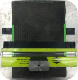
The Blintz fold which is used as the start of many origami pieces was fabricated to demonstrate the possibilities of folding multiple plies, Figure 33.
A Miura sheet was also fabricated to demonstrate a different type of flat folding, Figure 34.
FIGURE 34.MIURA FOLDING SHEET
FIGURE 35.BASIC ORIGAMI FLASHER MODEL DUAL-MATRIX DEMONSTRATION
Researchers at BYU developed a ‘modified origami flasher model’ concept for a deployable solar array directed by rules of rigid origami which allow for non-folding sections to remain semi or fully-rigid during actuation [8]. Using representational materials, a prototype of their mathematical model was fabricated (Figure 6) to demonstrate folding and actuation. In this research, using CFRS hinges, a simplified version of their mathematical model was fabricated to demonstrate the complexity of which a detailed architecture could be fabricated. Figure 36 shows the fold diagram of a zero panel thickness and finite thickness folding patterns, the second of which accommodates thickness of the solar cells.
For purposes of this fabrication demonstration all fold lines were created equal and a zero thickness model was assumed. A stencil of 1/6th the radially symmetric folding pattern was created in SolidWorks with line widths of 0.1 inch. This stencil was then 3D printed and used as a template in which to place the electrical tape bounding material. Templates of the electrical tape inserts were also printed such that fairly exact and consistent inserts could be quickly cut from a large sheet of tape. The template and pre-cut sections of tape were used to bound 1/6th of model before rotating the template and continuing the bounding. Figure 37 and 38 show fabrication steps and actuation of this design.
FIGURE 38.ORIGAMI FLASHER CONCEPT -STORAGE AND DEPLOYMENT
By adding panels which duplicate the stiffness of a flexible solar cell and adjusting hinge widths to account for changing fold diameter the deployed stiffness of this structure could be increased.
3.5 - Conclusion
Chapter 4 – Characterization
Characterization tests of epoxy infused HSC coupons are developed here to impart a near pure bending deformation. Loading is done through an Instron R4400 loading frame with a screw driven cross head, all tests presented herein are actuated through a displacement control. Strain measurements from beam theory are compared with values measured through imaging and using digital image correlation (DIC) software. The bending stiffness and empirical bending modulus of epoxy coupons are derived from the testing before extending the method to CFSR coupons. Tensile tests of joined verse non-jointed specimens are performed at 0-90o and ±45o angles to the fiber direction to characterize the effects of silicone on in-plane properties. Finally the flattening stiffness of the HSC CubeSat boom developed in chapter 2 is tested.
4.1 – Microstructure
The microstructure of fabricated specimens should be understood before full characterization derived from tensile and bending stiffness tests can be understood. The fiber volume fraction of a laminate is defined as the volume of fibers contained within a unit volume of the laminate. If no voids exist within the laminate the fiber volume fraction and matrix volume fraction add together to equal one. This ratio of fiber to matrix is an important target to meet as it affects structural properties of the laminate. Too little resin results in a part that has inadequate reinforcement to hold the fibers which results in an inability to transfer load between adjacent fibers and through the structure. Too much resin results in a matrix dominated part where the benefits of the stronger reinforcement are offset through increased mass and decreased strength. Typical fiber volume fractions of different molding processes can be seen in Table 3 [20]
TABLE 3.COMMON FIBER VOLUME FRACTIONS IN DIFFERENT PROCESSES [20]
Molding Process Fiber Volume Fraction
Contact Molding 30%
Compression Molding 40%
Filament Winding 60% - 85%
Measurement of this ratio can be done in several ways. Microscopy is an accurate method but would not be reliable with hyper elastic matrices that are easily damaged. A cross section of the laminate would need to be cut perpendicular to the fiber direction and the exposed fiber and matrix cross section then polished for examination under a microscope. In this visual method the fiber to matrix ratio is then counted in a variety of post processing methods. An image can be recorded and the area brightness values of fiber verses matrix are determined through computer analysis. Alternatively the fibers of known diameter can be counted within a unit area and the fiber volume ratio then determined mathematically. This method requires the reinforced fibers to be rigid so that polishing does not damage the exposed fiber ends. In this study the hyper elastic matrices in question would be unable to withstand polishing, resulting in a damaged cross section that would provide little information.
The simplest but not most accurate approach is to measure the mass fraction of the laminate by measuring the mass of the dry fibers before infusion and the mass of the entire laminate after infusion, while assuming the void content is zero. This value can be converted to a volume fraction using published values for the densities of each constituent. The following equation is used to determine the fiber volume fraction of a laminate once the fiber mass and cured laminate mass are known [20]:
𝑉𝑓 = 𝑀𝑓 𝜌𝑓 𝑀𝑓 𝜌𝑓 + 𝑀𝑚 𝜌𝑚
Table 4 shows the measured mass of each laminate before and after infusion and shows and the calculated fiber volume fraction for 2 and 4 player CRFS lamoinates. These values, while limited, show a low fiber volume fraction as expected.
TABLE 4.FIBER VOLUME FRACTION OF CFRS
Fiber Volume Fraction of CFRS
Ply Count Dry mass [gram] Infused Mass [gram] 𝑽𝒇
2 ply 1.91 5.26 27.5%
Computed Tomography (CT) x-rays of a 4 ply silicone laminate were also able to be recorded. A volume fraction was not measured from the images but it was seen that no irregularities from a silicone infusion were found in the fiber weave, Figure 39.
FIGURE 39.COMPUTED TOMOGRAPHY (CT)SCAN OF 4PLY CFRS
4.2 – Testing Approach of HSC
fabric were fabricated into a 0.1 inch thick plate and the bend specimens were cut using a water jet. However, properties calculated from these estimations were based on small deformation and it was uncertain how the large bending effected the structural response when modeled in an FEA software. For increased model correlation an alternative method to characterize mechanical properties of HSC must be investigated.
The characterization of fabricated booms and tape springs have been investigated in several works to verify operation or quantify performance of actual structures [1,4,5,6]. Other work has focused on FEA modeling techniques [3] or characterization of in-plane properties [18]. Continued work has sought to correlate physical test data of fabricated booms with FEA modeling where predictions of the bending stiffness were scaled according to results obtained from 4-point bend tests [22]. Fewer works, however, have sought to characterize or develop methods to measure the bending characteristics of thin HSC lamina which could then be used in predictive FEA models.
FIGURE 40.FOUR-POINT BEND FIXTURE AND F.B.D.[24]
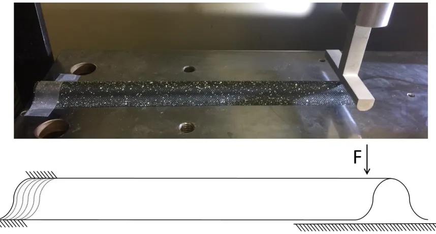
This led to the next work of interest which utilized a much simpler approach. Here bending stiffness of coupon samples are measured using a modified platen test to induce a near-pure bending response in samples which are sandwiched between two metallic plates, Figure 41 [11]. The plates are attached to moving cross heads using tape which act as simple pin joints. Knowing the reaction force and using the following free-body-diagram to determine moment arm and curvature of the coupon a bending stiffness is calculated.
A modified platen test similar to this would next be used to characterize material properties of epoxy laminates for correlation with FEA models. These same procedures will then also be used to characterize the silicone infused carbon fiber.
4.3 – Modified Platen Test
In addition to the coupon dimensions the pre-buckled length and tab angle should be measured before conducting the test. With a known load and platen displacement the following F.B.D. is used to determine the moment reaction of the hinge region, Figure 42.
FIGURE 42.DIMENSIONING AND FBD OF MODIFIED PLATEN TEST
The hinge width ‘b’ remains constant throughout the test and with a known tab angle equal to half the subtended curvature angle, the radius of curvature can be calculated.
𝐶𝑖𝑟𝑐𝑢𝑚𝑓𝑟𝑒𝑛𝑐𝑒 = 𝐶 = 2𝜋𝑟
𝐴𝑟𝑐 𝐿𝑒𝑛𝑡ℎ = 𝑏 = 𝐶
𝑠𝑢𝑏𝑡𝑒𝑛𝑑𝑒𝑑 𝑎𝑛𝑔𝑙𝑒 = 2𝜋𝑟 2𝜋
𝜙
𝐶𝑢𝑟𝑣𝑎𝑡𝑢𝑟𝑒 = 𝜅 = 1 𝑟=
2𝜃 𝑏
The moment arm ‘d’ and platen separation ‘2h’ can then be calculated from the position of the tabs, chord length and chord height of the bent specimen.
𝐶ℎ𝑜𝑟𝑑 𝐿𝑒𝑛𝑔𝑡ℎ = 𝑐 = 𝑟 sin (𝜙 2) =
𝑏
2𝜃sin(𝜃)
𝐶ℎ𝑜𝑟𝑑 ℎ𝑒𝑖𝑔ℎ𝑡 = 𝑟′= 𝑏
2𝜃− 𝑏
2𝜃cos(𝜃) = 𝑏
2𝜃(1 − cos(𝜃))
𝐻𝑎𝑙𝑓 ℎ𝑒𝑖𝑔ℎ𝑡 = ℎ = 𝐿 cos(𝜃) + 𝑐 = 𝐿 cos(𝜃) + 𝑏
2𝜃sin(𝜃)
𝐴𝑟𝑚 𝐿𝑒𝑛𝑔𝑡ℎ = 𝑑 = 𝐿 sin(𝜃) + 𝑟′= 𝐿 sin(𝜃) + 𝑏
2𝜃(1 − cos(𝜃))
With these relations, a MatLab script was written to solve for the tab angle ‘ϴ’ using the known value of ‘h’ calculated from the vertical cross head displacement. The angle was then used to solve for the moment arm length and assumed constant curvature. The reaction moment was found next and normalized per unit width by dividing the result by the specimen width.
𝑀𝑜𝑚𝑒𝑛𝑡 𝑈𝑛𝑖𝑡 𝑊𝑖𝑑𝑡ℎ=
𝑀
𝑤 = 𝑀𝑛𝑜𝑟𝑚 =
(𝐹𝑑 − 𝑚𝑑2)
𝑤 =
𝑑 (𝐹 −𝑚2 )
𝑤
According to the ABD stiffness matrix of a composite lamina the D terms are the associated bending stiffnesses relating moments to curvatures [23]. The empirical bending stiffness of the coupon can then be calculated by taking the slope of the moment verse curvature plot. An example of this plot can be seen in Figure 43.
FIGURE 43.MOMENT VS.CURVATURE RELATION -EMPIRICAL BENDING STIFFNESS D11
The stress imparted to the specimen would next be calculated using standard mechanics of materials approach. The in-plane stress is defined as force per compressive area.
𝜎𝑛𝑜𝑟𝑚𝑎𝑙 =𝐹
𝐴 =
𝐹 𝑤𝑡
The stress imparted from the bending moment is defined as the moment per section modulus. The section modulus is then defined as the area moment of inertia divided by half the specimen height, which in this case is the thickness [25].
𝑆𝑒𝑐𝑡𝑖𝑜𝑛𝑀𝑜𝑑𝑢𝑙𝑢𝑠 = 𝑆 =𝑡𝐼 2
⁄ =
1 6𝑤𝑡
2
𝜎𝑏𝑒𝑛𝑑 =𝑀
𝑆 =
6 𝑀 𝑤𝑡2
𝜎𝑏𝑒𝑛𝑑 =6𝑀𝑛𝑜𝑟𝑚 𝑡2
In the modified platen approach described in previous work [11], in-plane stress was compared with the bending stress to determine how much effect each type of loading had on the coupon. Comparing these the following relation can be determined.
𝜎𝑏𝑒𝑛𝑑 = 6 𝑀 𝑤𝑡2 =
6 𝐹𝑑 𝑤𝑡2 =
6𝑑
𝑡 𝜎𝑛𝑜𝑟𝑚𝑎𝑙
The difference then becomes the result of the changing arm length. For a minimum and maximum arm length this is roughly 200-700 times smaller and therefore can be neglected.
Finally, in addition to the bending stiffness and associated stress levels the effective bending modulus may be calculated through the measuring of the slope of a stress-strain plot. Strain can be determined using two different methods. The first looks toward beam theory for the prediction that face strains may be calculated from a known curvature and distance from neutral axis. Recall the formula for curvature and assuming a geometrically centered neutral axis the following strain relation is developed [25].
𝜀𝑥 = −𝑦 𝜌
𝜅 =1 𝜌
𝜀𝑓𝑎𝑐𝑒 = −𝜅𝑦 = −𝜅𝑡 2
4.4 – DIC Strain Measurement
Engineering strain measurements have typically been captured by externally mounted strain gauges. A thin metallic pattern attached to an adhesive changes electrical resistance when deformed and resistance is then equated to strain. Strain gauges can detect extensions in one or more axis but are limited to a narrow range of deformations and are unable to measure global responses. Digital image correlation is a technology that examines a speckle pattern which is imprinted on the surface of the test specimen from which deformations and strains can be calculated. The speckle pattern and background must have distinguishing contrast in brightness so the camera system can detect a pattern. Such a pattern can be inherent to the surface texture or applied externally as a pattern of colored stickers or painted speckles. If the pattern is applied externally it is important that the sticker or paint is able to deform with the base material of the specimen, otherwise the measurement is not symbolic of the specimen but that of the speckled pattern as it delaminates from the specimen’s surface. This type of system is capable of measuring strains from fractions of a percent up to several hundred or more percent. Correlated Solutions VIC2-D and VIC3-D DIC software is available and were used to measured deformations and strains in all subsequent testing.
FIGURE 44.SPECKLE PATTERN OF BENDING SPECIMEN
4.5 – Simple Joint in Bending
The fundamental mechanical response of CFRS hinges and thin high straining laminates subject to large curvature is their bending stiffness. The modified platen method described earlier will be used here for epoxy and then silicone infused coupons arranged at both 0-90o and ±45o fiber orientations.
FIGURE 45.TAB BONDING OF EPOXY INFUSED COUPONS
Next, three ply silicone infused sheets were fabricated and coupons cut in the same manor. Only a single tab per end was used with the silicone to keep from increasing the coupons moment mass. In addition to the first set of silicone samples, three layer continuous fiber hinge specimens with epoxy infused carbon tabs were fabricated and cut to the same 0.75inch x 2.43inch size. Figure 46 shows speckled pattern on of each type of bending coupon to be tested.
Finally, to exploit micro buckling characteristics of the hinge, four-layer specimens infused with a continuous silicone hinge would be compared to four layer specimens where two two-layer laminates were bonded together during their second epoxy cure, Figure 47. These ‘2+2’ split hinge specimens are allowed to deform independently through the hinge region and their ultimate stiffness is compared.
FIGURE 47.'2+2'PLY VERSE 4PLY SILICONE HINGE AND SECONDARY EPOXY INFUSION PROCESS
FIGURE 48.PRE-BUCKLED INSTALLATION
FIGURE 49.DIC3DSTRAIN AND 2DCURVATURE SETUP FOR BENDING TEST
The epoxy coupons held a very consistent curvature throughout the entire compression and as expected the 0-90o samples were stiffer than the ±45o samples. The moment was normalized by the specimen width and a moment verse fold angle for a 0-90o sample can be seen in Figure 50.
FIGURE 50.NORMALIZED MOMENT VERSE FOLD ANGLE OF EPOXY INFUSED COUPONS
Results calculated from taking a best fit line of the assumed and measured curvatures are presented in Table 5. Figure 52 shows an example plot of the response and the best fit line according to the DIC measured curvature. As expected the variation in fiber orientation away from the 0o direction had a decreasing effect on stiffness.
FIGURE 52.D11STIFFNESS AND ‘BEST-FIT’ OF EPOXY INFUSED COUPONS ACCORDING TO DICMEASUREMENTS
TABLE 5.D11BENDING STIFFNESS OF EPOXY INFUSED COUPONS
Bending Stiffness D11 of epoxy Infused Coupons [M/
𝜿
]Sample 0-90o CC 0-90o DIC 45o CC 45o DIC
1 0.031 0.0331 0.0183 0.0169
2 0.0293 0.0269 0.0198 0.0171
3 0.0298 0.0281 0.0201 0.0187
4 0.0283 0.0296 0.0198 0.0174
5 - - 0.0207 0.0183
6 0.0307 0.0282 0.0176 0.0172
Average: 0.02982 0.02918 0.01938 0.0176
Std Dev: 0.00109 0.00239 0.00118 0.000727
In calculating the effective bending modulus several strains, explained in section 4.3, were looked at. First the strain measured from the surface of the specimen obtained through DIC was used. The curvature of the surface exported by DIC and the assumed constant curvature were next used to calculate a strain based on standard beam theory. In the case of epoxy infused coupons, no buckling is observed on the inner face and a geometrically centered neutral axis is assumed.
𝜀𝑓𝑎𝑐𝑒 = −𝜅𝑡 2
The DIC face strain was by default calculated as a Lagrange strain but measured to be much less than the curvature assumptions. To add confidence to this large bending measurement other approaches were also calculated within the DIC software and found to be in close agreement. A plot of the various strain calculations can be seen in Figure 54.
FIGURE 54.COMPARISON OF DICSTRAIN CALCULATION METHODS
FIGURE 55.STRESS VS.STRAIN OF 0-90OSPECIMEN ACCORDING TO DIFFERENT STRAIN MEASUREMENTS
All other epoxy infused specimens followed a similar trend. Tables 6 and 7 show the empirical bending modulus values for the 0-90o and ±45o coupons taken from the slope of a best fit line, similar to the one in Figure 52. Both sets of data exhibited consistent values among specimen type and percent differences were kept between 3.6% and 8.7% depending on which strain measurement technique was used for the calculation.
TABLE 6.MODULUS OF 0-90O EPOXY COUPONS
Empirical Bending Modulus of 0-90o Epoxy Infused Coupons Sample
No.
DIC measured [psi]
Const Curve [psi]
DIC Curve [psi]
1 1,196,600 371,800 397,700
2 1,120,000 351,300 322,500
3 1,130,400 357,100 337,300
4 1,198,000 340,000 355,400
5 - - -
6 1,323,700 368,600 338,200
Average: 1,193,740 357,760 350,220
Std Dev: 81,187 12,964 28,987
TABLE 7.MODULUS OF 45OEPOXY COUPONS
Empirical Bending Modulus of 45o Epoxy Infused Coupons Sample No. DIC measured [psi] Const Curve [psi] DIC Curve [psi]
1 678,930 219,010 202,380
2 653,100 237,440 205,040
3 653,430 241,420 223,980
4 631,680 237,090 208,880
5 546,010 248,260 219,660
6 712,870 211,430 206,680
Average: 646,003 232,442 211,103
Std Dev: 56,329 14,137 8,676
Error: 8.7% 6.1% 4.1%
In both fiber orientations the DIC measured face strains produced a bending modulus about 3 times greater than that of the DIC curvature calculated strain. This is a direct result of the factor of 3 discrepancy seen in the strain measurement techniques and future investigation should focus on this discrepancy to determine more closely what the actual response is.
FIGURE 56.CURVED GEOMETRY OF 0-90OSILICONE COUPONS WITH ALUMINUM TABS
TABLE 8.EMPIRICAL BENDING MODULUS AND D11STIFFNESS OF 0-90O SILICONE COUPONS WITH ALUMINUM TABS
Empirical Modulus and D11 Stiffness 0-90o Silicone Infused Aluminum Tab Coupons Sample
No.
DIC measured [psi]
DIC Curve [psi]
D11 - DIC [M/
𝜿
]1 30,041 10,087 0.0084
2 - - -
3 35,004 8,079 0.0072
4 33,139 8,625 0.0077
5 23,440 8,123 0.0067
6 34,172 6,439 0.0046
Average: 31,159 8,271 0.00692
Std Dev: 4,707 1,307 0.001441
FIGURE 57.CURVED GEOMETRY OF ±45OSILICONE COUPONS WITH ALUMINUM TABS
TABLE 9.EMPIRICAL BENDING MODULUS AND D11STIFFNESS OF ±45O SILICONE COUPONS WITH ALUMINUM TABS
Empirical Modulus and D11 Stiffness
±45o Silicone Infused Aluminum Tab Coupons
Sample No.
DIC measured [psi]
DIC Curve [psi]
D11 - DIC [M/
𝜿
]1 - - -
2 33,459 8,215 0.012
3 28,577 10,003 0.0077
4 34,878 9,065 0.008
5 33,292 9,193 0.0093
6 32,319 9,610 0.0111
Average: 32,505 9,217 0.00962
Std Dev: 2,378 671 0.00189