Vol. 3, Issue 3, March 2015
Design of Microstrip Patch Antenna for
GPS Applications using EBG Structures
Naveen JVSS
1, Varun Kumar.K
2, Ramesh.B
3, Vinay. K.P
4Department of E.C.E, Raghu Engineering College, Visakhapatnam, Andhra Pradesh, India1, 2
Associate Professor, Department of E.C.E, Raghu Engineering College, Visakhapatnam, Andhra Pradesh, India3,4
ABSTRACT: A circularly polarized microstrip patch antenna for Global Positioning System (GPS) is proposed. In this
paper we have discussed and analysed the performance of square shaped microstrip patch antenna in L1 and L2 bands. Operating range of GPS is 1.227 GHz (L2 Band) to 1.575 GHz (L1 Band). The proposed design operates at resonant
frequency of fr =1.5GHz. Further EBG structure is incorporated into the actual design in stages of several iterations and
various parameters such as Return Loss, VSWR are analysed. Improvement in gain and axial ratio bandwidth are observed when compared to antenna designs without EBG. The proposed antenna is designed and simulated using CST
Studio suite version-14.Co-axial probe feeding technique is used.
KEYWORDS:Axial ratio, Electromagnetic Band gap structures (EBG), VSWR, GPS Antennas, Patch antenna, Global
Positioning System (GPS)
I. INTRODUCTION
The GPS (Global Positioning System) has revolutionized modern day navigation and position location. It is now the means of tracking and location mapping in most of the aircraft carriers, ships and even in automobiles. [1] With advancement in technology and science, GPS applications are even used by common public for the want of updating location, tracking purposes and even travelling from one place to another [2]. Most of the GPS Antennas require circular polarization and this is achieved by microstrip antennas [3] which satisfy criteria like low cost (economically feasible), ease of fabrication, miniaturization along with high precision and reliability. Design of a patch antenna on a high dielectric constant substrate results in a highly inefficient radiator due to surface wave losses and has a very narrow bandwidth and even less gain [5]. All these effects can be eventually minimized by printing EBG structures on high dielectric substrates.
GPS operates under the frequency of 1.227GHz (L2 Band) to 1.575 GHz (L1 Band). [3] To produce GPS operating frequency, many complex designs are proposed earlier. These complex designs increase the fabrication cost. In order to reduce the fabrication cost and to improve the antenna parameters we propose a simple square shaped patch antenna operating at 1.227-1.575 GHz to operate at GPS frequencies. Later EBG structure is incorporated into the design.
Surface waves reduce antenna efficiency, gain, limit bandwidth, increase end fire radiation, increase cross-polarization levels, and limit the applicable frequency range of microstrip antennas [4]. A simple EBG structure comprises of elements interconnected with each other to form an array of metallic parts embedded in a slab of dielectric. Sometimes metallic pins (or via) are introduced to prevent electromagnetic waves from traveling in the waveguide between the array and the ground. Each unit cell essentially behaves as a microwave resonant circuit. [4]
II. RELATED WORK
In [1] authors used a single-feed low profile to fabricate circularly polarized microstrip patch antenna for GPS Applications. For dual frequency operation they etched four slots for generating circular polarization. They used stub loading and the frequency ratio of two bands of the antenna was reduced to 1.1 .Simulation results show that the gain of
the antenna in the L1 and L2 bands are approximately 6.46 and 6.78 dB respectively. The antenna efficiency is about
[3] the antenna was constructed by using a low-loss substrate material (R-4726), manufactured by Matsushita. It had a thickness of 3.12 mm and a relative permittivity of 3.6. They achieved enhanced gain at lower angles without sacrificing the circular polarization performance. They designed a pyramidal configuration appeared to exhibit good promise and favourable potential for further improvement. In [4] the authors designed a compact high-performance circularly-polarized microstrip antenna for the global positioning system. It comprises a fractal hi-impedance surface electromagnetic bandgap (EBG) structure printed on a high permittivity substrate. Results show that the proposed Global Positioning System antenna has good axial ratio performance in the upper half-plane, an improvement in gain and a significantly wider axial ratio bandwidth when compared to the same antenna without EBG. From the above designs, the performance of antenna improved with increase in design complexity. So we propose a microstrip patch antenna with simple EBG structure for GPS applications by reducing the design complexity.
III. ANTENNA DESIGN
A. Design of Microstrip Patch antenna for GPS applications:-
A square shaped patch antenna (27.8×27.8mm) is designed with one slit at the centre and one at the edge. The proposed
antenna is designed using ROGERS TMM10 substrate with dielectric constant ɛr=10.2, and thickness of the substrate is
h=1.905mm.Due to certain limitations , the port region must be homogeneous for atleast three mesh lines in longitudinal direction, so the thickness of the ground plane should be 3 times to the substrate thickness i.e.,(3h)
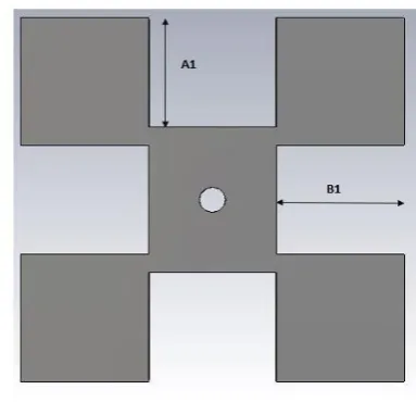
The ground plane is of size 80×80 mm. Coaxial probe feed technique is used for the antenna to get desired performance. In contrast to antenna without EBG, the proposed antenna shown in Fig. 1.1, yields higher gain and wider bandwidth due to the reduction of surface waves. FIG.1.1 shows the general configuration of proposed square shaped microstrip patch antenna where EBG structures are inserted over the ROGERS TMM10 substrate and dimensions of microstrip patch antenna are tabulated in a tabular form.
FIG1.1 GEOMETRY OF PROPOSED EBG ANTENNA TABLE 1: DIMENSIONS OF THE DESIGNED ANTENNA
B. SCHEME OF THE FRACTAL ITERATION STRUCTURE
The GPS Antenna with EBG structures mounted is compared in several stages of iterations.
The initial shape is the square patch of size A (0th iteration).The patch is then rescaled in the preceding iterations as
following A1=A/3, B1=(4/5)A1, A2=A1/3, B2=(4/5)A2.
The period P of the proposed EBG structure is 15mm. Each fractal patch of the proposed design is connected to the ground plane through a shorting pin of radius 1 mm. The distance from centre of the patch to the feed point is 3.1mm.
_ LENGTH (MM)
Lp 27.8
Wp 27.8
L1 5
L2 2
W1 1
W2 0.6
Vol. 3, Issue 3, March 2015
TABLE 1: DIMENSIONS OF THE DESIGNED ANTENNA
FIG 1.2 0TH ITERATION FIG 1.3 1ST ITERATION
Where A is the length and width of fractal EBG structure
FIG 1.4 2ND ITERATION
DESIGN PARAMETER LENGTH(MM)
A 14.4
A1 4.8
A2 1.6
B1 4.32
IV. RESULTS & DISCUSSION
In the figure 1.5 it is shown that at frequency range of 1 -2 GHz the plot shows the VSWR to be 1.046 at resonant frequency of 1.476 GHz. If VSWR is 1 that indicates reflection coefficient is maintaining value of zero which is not practically possible, always there is some amount of reflection exists for any antenna practically. So VSWR is maintaining <1.5 or 2, then it is clear that the designed antenna is an efficient radiator.
FIG 1.5 VSWR VERSUS FREQUENCY PLOT
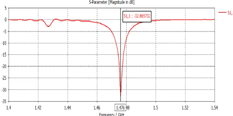
S11 is a measure of how much power is reflected back at the antenna port due to mismatch from the transmission line.
When EBG structures are not mounted the return loss was found to be -5.07 dB thereby resulting in coupling mismatch.
At the end of 3rd iteration the return loss was found to be -32.865 dB as shown in fig. 1.6.VSWR is minimized to 1.04,
so maximum power is coupled between the transmission line and the antenna.
Vol. 3, Issue 3, March 2015
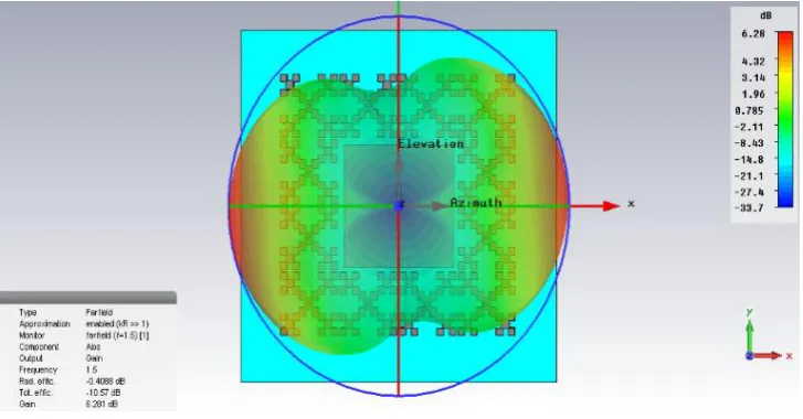
FIG 1.7 2D FARFIELD OF RADIATION PLOT OF DESIGNED ANTENNA
This representation of gain corresponds to two vertical cuts of an “apple” type which is the typical pattern of a GPS patch antenna at cross angles to each other as shown in fig. 1.7. These radiation patterns tells us the most important information about the real-life antenna performance in the field such as the antenna‟s ability to receive signals from satellites at low altitudes, or to be able to compare relative performance of one antenna against another. Fig. 1.8 shows the 3D Model of farfield gain along with the designed GPS antenna.
FIG 1.8 3D MODEL OF FARFIELD GAIN ALONG WITH THE DESIGNED GPS ANTENNA
V. CONCLUSION
The designed microstrip patch antenna can be used for GPS applications under the frequency band of 1.227-1.575 GHz. VSWR calculated is observed to be 1.04 at resonant frequency of 1.476 GHz which clearly shows it as an efficient radiator and maximum power is coupled between the transmission line and the antenna. From the results it is clear that the measured axial ratio is less than 3db for the proposed antenna. Different parameters of Antenna are analysed clearly with and without EBG clearly depicting the advantage of using EBG structures to suppress surface waves and for
was used the return loss was found to be -28.07 dB. When 2 Iteration was used the return loss was found to be -32.86 dB.
REFERENCES
[1] A. A. Heidari, M. Heyrani, and M. Nakhkash, A dual-band Circularly Polarized stub loaded Microstrip patch antenna for GPS Applications,
Progress In Electromagnetics Research, PIER 92, 195–208, 2009.
[2] Yashu Rajput, Tejender Singh Rawat and Leena Varshney , „CPW Feed Patch Antenna for GPS Applications‟ , International Journal Of Computational Engineering Research (ijceronline.com), Vol. 2 Issue. 6.
[3]R. Mittra* and R. Yang, M. Itoh and M.Arakawa „MICROSTRIP PATCH ANTENNAS FOR GPS APPLICATIONS‟, IEEE, 0-7803-1246-5/93 0 1993.
[4]Dalia M.N. Elsheakh, Hala A. Elsadek and Esmat A. Abdallah Electronics Research Institute, Giza,‘Antenna Designs with Electromagnetic Band Gap Structures‟, IEEE ANTENNAS AND WIRELESS PROPAGATION LETTERS, VOL. 5, 2006.