Design of Smart Controller for Speed Control
of DC Motor
Kanhai Kumhar
1, Amit Kumar
2, Dwigvijay Kushwaha
3Lecturer, Dept. of Electrical Engineering, K.K. Polytechnic, Govindpur, Dhanbad, Jharkhand, India1
PG Student, Dept. of Electrical Engineering, DRIEMS, Cuttack, Odhisa, India2
Ph.D. (Pursuing), Dept. of Electrical Engineering, SSSUTMS, Bhopal, Madhya Pradesh, India3
ABSTRACT:This paper uses NEURO FUZZY TECHNIQUE in estimating speed and controlling it for a separately excited DC motor. The rotor speed of the dc motor can be made to follow an arbitrarily selected trajectory. The purpose is to achieve accurate trajectory control of the speed of separately excited DC Motor, especially when the motor and load parameters are unknown.
Such a neuro fuzzy control scheme consists of two parts. One is the neural identifier which is used to estimate the motor speed error (state error or state error derivative). The second is the fuzzy logic controller which is used to generate a control signal for a chopper & speed control of separately excited DC Motor.
The purpose of this technique is to achieve accurate trajectory control of the speed. Such a control scheme consists of two parts. One is the neural identifier which is used to estimate the motor speed. The other is the neural fuzzy logic controller which is used to generate the control signal (fuzzy output).
KEYWORDS: Neuro Fuzzy Technique, Fuzzy Logic.
I.INTRODUCTION
The development of high performance motor drives is very important in industrial as well as other purpose applications. Generally, a high performance motor drive system must have good dynamic speed command tracking and load regulating response.
The dc motors are used in various applications such as defense, industries, Robotics etc. DC drives, because of their simplicity, ease of application, reliability and favorable cost have long been a backbone of industrial applications. DC drives are less complex with a single power conversion from AC to DC. DC drives are normally less expensive for most horsepower ratings. DC motors have a long tradition of use as adjustable speed machines and a wide range of options have evolved for this purpose. In these applications, the motor should be precisely controlled to give the desired performance. Many varieties of control schemes such as P, proportional integral (PI), proportional derivation integral (PID), adaptive, and fuzzy logic controller (FLCs), have been developed for speed control of dc motors. The proposed controller systems consist of multi-input fuzzy logic controller (FLC) and multi-input integrated fuzzy logic controller (IFLC) for the speed control.
II.EXISTING WORK
Previously PID controllers were used in estimating speed and controlling it for a separately excited DC motor. The rotor speed of the dc motor can be made to follow an arbitrarily selected trajectory.We have designed a DC motor whose speed can be controlled using PID controller. The proportional, integral and derivate (KP, KI, KD) gains of the
PID controller are adjusted using Ziegler’s Nichols technique.
fuzzy set theory, introduced by LA Zadeh in 1973 and applied (Mamdani 1974) in an attempt to control system that are structurally difficult to model.
III. SYSTEM MODEL
The fuzzy logic foundation is based on the simulation of people's opinions and perceptions to control any system. One of the methods to simplify complex systems is to tolerate to imprecision, vagueness and uncertainty up to some extent. Fuzzy provides a remarkably simple way to draw definite conclusions from vague ambiguous or imprecise information. It is suitable for applications such as the speed control of dc motor which has non-linearities.
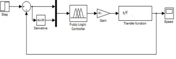
Fig.1 Fuzzy simulink model of the system
Before running the simulation in MATLAB/SIMULINK, the Fuzzy Logic Controller is to be designed. This is done using the FIS editor. FIS file is created using the Fuzzy logic toolbox. The design of a Fuzzy Logic Controller requires the choice of Membership Functions. After the appropriate membership functions are chosen, a rule base is created. The set of linguistic rules is the essential part of a fuzzy controller. The response of the fuzzy logic controller is
obtained using in MATLAB/SIMULINK. A two input which is Speed Error (e) & Change in Error (ec) and one –
output Change in control, fuzzy controller is created and the membership functions and fuzzy rules are determined.
IV. CONSTRUCTION OF RULES AND RULE VIEWER
The goal of designed FLC in this study is to minimize speed error. In addition, the change of error plays an important role to define controller input. Consequently FLC uses error (e) and change of error (Ce) for linguistic variables which are generated from the control rules.
Table I RULE TABLE FOR OUTPUT
VARIABLE CONTROL
In figure 2 fuzzy if-then rules are shown and in table 1 analysis of the two inputs (error and change in error) and output are shown. There are total 9 rules output variable.
e/ec (ecl) (ecm) (ech)
el ol om om
em ol om oh
Fig.2 Fuzzy if then rule
V. SIMULATION/EXPERIMENTAL RESULTS
STEP RESPONSES
The simulation output of the Fuzzy Logic Controller for System is represented in Figure. 4. Here a simulink diagram of fuzzy logic controller is given which is constructed using fis file.
Fig.4. Simulation output of the Fuzzy Logic Controller
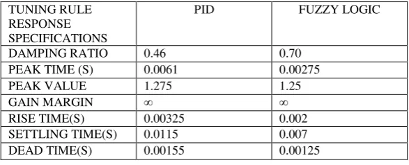
For comparison between the two types of controller we put the results of both the controllers in a tabular form as shown in the table II below:
Table II COMPARISION TABLE
V. CONCLUSION
From the above table we find that the response of the smart controller is much better than the response obtained from the classical controllers like P, PI & PID. The peak time is reduced and the settling time is also reduced. Also from the response curve we find that the maximum overshoot is also reduced. We also see that to reduce the maximum overshoot from the response by the use of classical controllers, we have to use the Zieglers Nichols tuning method
TUNING RULE RESPONSE
SPECIFICATIONS
PID FUZZY LOGIC
VI. FUTURE SCOPES
Although the current system is fully functional, several new techniques can also be used to design different types of smart controllers. These are outlined here for the benefit of anyone continuing this project, and to increase the general understanding of the subject.
The simulink model can be improved in many ways. We can use some gains, integrals and derivatives to improve the response further so that our output becomes smoother and less error is present.
Here we have considered only the armature control method. But there are some other methods of speed control like field control method etc. We will implement these modern control methods to these speed control method also and try to find the best method.
Also we have considered here is a separately excited DC motor. But there are many other types of DC motors on which we will try to study the control method of these motors too using all the above mentioned methods.
In future we will also try to use these methods to some of the rotating AC machines like induction motors and study their responses with different controllers.
REFERENCES
[1] Salim, JyotiOhri, Naveen, “speed control of DC motor using fuzzy logic – lab view” [2] B Sharmila and N Devarajan, “performance of networked DC motor using fuzzy logic”
[3] J. N. Rai, 2Mayank Singhal, 3MayankNandwani, “Speed Control of Dc Motor Using Fuzzy Logic Technique” [4] Snehashish Bhattacharjee1, Samarjeet Borah2, “A survey on fuzzy logic controller of DC motor”
[5] Ritu Shakya1, Kritika Rajanwal2, Sanskriti Patel3 and Smita Dinkar4, “Design and Simulation of PD, PID and Fuzzy Logic Controller for Industrial Application”
[6] Singariv.s.rPavankumar and Y.B.Venugopal “A Neuro-Fuzzy Based Speed Control of Separately Excited DC Motor” IEEE International conference, 2010”
[7] M.Murugandam&M.Madheswaran,” Modeling and Simulation of modified fuzzy logic controller for various types of DC motor drives IEEE International conference on control system june 2009”
[8] Atul Kumar Dewangan, SashaiShukla, VinodYadu “Speed Control of a Separately Excited DC Motor Using Fuzzy Logic Control Based on Matlab Simulation Program”
[9] Zadeh L. A., "Outline of a New Approach to the Analysis of Complex Systems and Decision Processes",
[10] Mrs.A.AThorat, Prof.SuhasYadav, Prof.S.S.Patil, “Implementation of Fuzzy Logic System for DC Motor Speed Control using Microcontroller”
[11] J. N. Rai, MayankSinghal, MayankNandwani, “Speed Control of Dc Motor Using Fuzzy Logic Technique”