Temperature Control of Steam Using
Microcontroller Arduino MEGA 2560
Muthuvignesh M1, Karthick.M1, Nallakaruppan.M 1, Jagadeshkumar S1, Sathishkumar R2
B. E Student, Dept. of EEE, Sri Krishna College of Technology, Coimbatore, India1
Assistant Professor, Dept. of EEE, Sri Krishna College of Technology, Coimbatore, India2
ABSTRACT:The efficiency of turbine is depend up on the temperature of generated steam.The generated steam temperature should be under control to avoid fatigue of turbine blade and reduce pressure of super heater.For this we considered set point to be at 535.c, a spray valve is to be used at super heater header. For maintaining the temperature, PID helps to function the spray valve in super heater in Tuticorin thermal power plant. In this proposed project a control mechanism using MicrocontrollerArduino Mega 2560 is tobemaintaining the necessary temperature of super heater. Because Arduino is single board microcontroller contrive to engender applications, interactive controls, or environments easily adaptive.The ATmega328P is a low-power CMOS 8-bit microcontroller supported on the AVR heighten RISC architecture. By accomplish powerful instructions in a single clock cycle, the ATmega328P attain throughputs approaching 1 MIPS per MHz permit the system designer to modify power consumption against processing speed.
KEYWORDS: Arduino mega 2560, Super heater, Temperature. I. INTRODUCTION
There are impressive alteration in power generation owing to deregulate. This lead to more rigorous requisite on the processes in control systems. It is mandatory to proceed the operating conditions to be more precise to satisfy the requirements. One way to attain this is to incorporate more process knowledge into the systems. This report presents a temperature control of super heater which is a crucial part of the most power plants. So we are usingArduino Mega 2560 which is a microcontroller board found on the ATmega2560. It has 54 digital input/output pins (of which 14 can be used as PWM outputs),16analoginputs, 4 UARTs (hardware serial ports), a 16 MHz crystal oscillator, a USB connection, a power jack, an ICSP header, and a reset button. It contains everythingneeded to support the microcontroller; simply connect it to a computer with a USB cable orpower it with a AC-to-DC adapter or battery to get started.[1][2]
II.RELATED WORK
III. TEMPERATURE CONTROL OF STEAM USING MICROCONTROLLER ARDUINO MEGA 2560
In this Proposed scheme, we are using microcontroller arduino mega2560,in which temperature and pressure of steam are measured by using temperature sensor and pressure sensor and they are amplify using amplifier, it also consist of LCD to display values, and consist of DC Gear Motor with relay and driver circuit.
MICRO CONTROLLER ARDUINO MEGA 2560:
Block Diagram
Fig. 1
Figure 1 elucidates the block diagram of microcontroller arduino mega 2560.
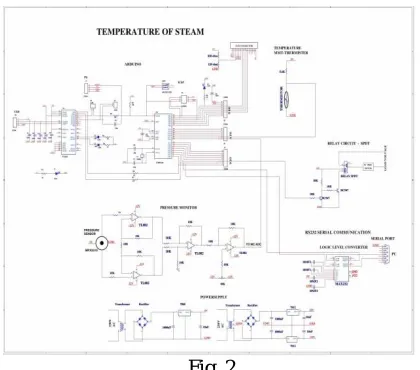
TEMPERATURE OF STEAM:
Schematic Diagram:
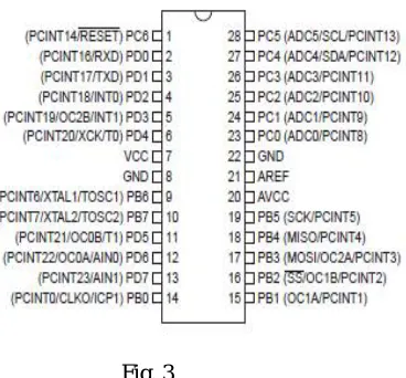
PINDETAILS:
Fig. 3
Figure 3 shows the PIN DETAILS diagram of arduino mega 2560 microcontroller.
Pin Descriptions: VCC:
Digital supply voltage.
GND: Ground.
Port B (PB7:0) XTAL1/XTAL2/TOSC1/TOSC2:
Port B is an 8-bit bi-directional I/O port with internal pull-up resistors (selected for each bit). The Port B output buffers have symmetrical drive characteristics with both high sink and source capability. As inputs, Port B pins that are externally pulled low will source current if the pull-up resistors are activated. The Port B pins are tri-stated when a reset condition becomes active, even if the clock is not running.
Port C (PC5:0):
Port C is a 7-bit bi-directional I/O port with internal pull-up resistors (selected for each bit). The PC5..0 output buffers have symmetrical drive characteristics with both high sink and source capability.
PC6/RESET:
ARDUINO
BLOCK DIAGRAM:
Fig. 4
Figure 4 elucidates the block diagram of microcontroller arduino mega 2560.
The AVR core combines a rich instruction set with 32 general purpose working registers. All the32 registers are directly connected to the Arithmetic Logic Unit (ALU), allowing two independent registers to be accessed in one single instruction executed in one clock cycle. The resulting architecture is more code efficient while achieving throughputs up to ten times faster than conventional CISC microcontrollers.
The ATmega328P provides the following features: 4K/8K bytes of In-System
Programmable Flash with Read-While-Write capabilities, 1K bytes EEPROM, 2K bytes SRAM, 23 general purpose I/O lines, 32 general purpose working registers, three flexible Timer/Counters with compare modes, internal and external interrupts, a serial programmable USART, a byte-oriented 2-wire Serial Interface, an SPI serial port, a 6-channel 10-bit ADC (8 6-channels in TQFP and QFN/MLF packages), a programmable Watchdog Timer with internal Oscillator, and five software selectable power saving modes. The Idle mode stops the CPU while allowing the SRAM, Timer/Counters, USART, 2-wire Serial Interface, SPI port, and interrupt system to continue functioning. The Power-down mode saves the register contents but freezes the Oscillator, disabling all other chip functions until the next interrupt or hardware reset. In Power-save mode, the asynchronous timer continues to run, allowing the user to maintain a timer base while the rest of the device is sleeping. The ADC Noise Reduction mode stops the CPU and all I/O modules except asynchronous timer and ADC, to minimize switching noise during
ADC conversions. In Standby mode, the crystal/resonator Oscillator is running while the rest of the device is sleeping. This allows very fast start-up combined with low power consumption.
Power supply: Block diagram:
Block diagram (Power s supply)
The ac voltage, typically 220V rms, is connected to a transformer, which steps that ac voltage down to the level of the desired dc output. A diode rectifier then provides a full-wave rectified voltage that is initially filtered by a simple capacitor filter to produce a dc voltage. This resulting dc voltage usually has some ripple or ac voltage variation. A regulator circuit removes the ripples and also remains the same dc value even if the input dc voltage varies. This voltage regulation is usually obtained using one of the popular voltage regulator IC units
Temperature measurement Using Thermistor: Schematic diagram :
Fig. 6 Figure 6shows the schematic diagram of temperature measurement.
Schematic Explanation:
In this circuit the thermistor is used to measure the temperature. Thermistor is nothing but temperature sensitive resistor. There are two type of thermistor available such as positive temperature co-efficient and negative temperature co- efficient. Here we are using negative temperature co-efficient in which the resistance value is decreased when the temperature is increased.
PRESSURE MONITOR Schematic Diagram:
Fig. 7 Figure 7shows the schematic diagram of pressure measurement.
where:
p is the pressure
F is the normal force
A is the area.
Pressure is a scalar, and has SI units of pascals, 1 Pa = 1 N/m2.
Pressure is transmitted to solid boundaries or across arbitrary sections of fluid normal to these boundaries or sections at every point. It is a fundamental parameter in thermodynamics and it is conjugate to volume.
Circuit description:
This circuit is designed to measure the varying pressure. The pressure is measured by diaphragm which is one type of transducer. When pressure is applied, the diaphragm is moving in the forward side. The diaphragm moving is depends on the pressure. So it generates the voltage pulse depends on the movement of diaphragm. The voltage pulses are in the range of milli voltage. Hence the voltage pulse is given to Instrumentation amplifier section in order to amplify the signals,The important features of instrumentation amplifier are high gain accuracy, high CMRR, low output impedance. Here the instrumentation amplifier is constructed by TL 074 operational amplifier. The TL 074 is the dual operational amplifier that is two operational amplifiers is fabricated in single chip. Here the instrumentation amplifier acts as differential instrumentation amplifier. The diaphragm transducer terminals are connected to A1 and A2 amplifier of the differential instrumentation amplifier. The difference of the varying voltage signals from the transducer is amplified by the instrumentation amplifier. The A4 amplifier is used for zero adjustment. When there is no pressure the diaphragm may be sliding in the forward or reverse side. Due to that instrumentation amplifier delivered some voltage at the output. To avoid this problem A4 amplifier is used for zero adjustment. Hence when there is no pressure the output is zero. The A5 amplifier acts as gain amplifier in which variable resistors is connected as feedback resistor. By adjusting the feedback resistor we can vary the gain of the output signal. Then the final gain adjusted signal is amplified by the A6 amplifier.
Spar gear:
A gear wheel is a wheel with teeth around its circumference, the purpose of the teeth being to mesh with similar teeth on another mechanical device -- possibly another gear wheel -- so that force can be transmitted between the two devices in a direction tangential to their surfaces. A non-toothed wheel can transmit some tangential force but will slip if the force is large; teeth prevent slippage and allow the transmission of large forces.A gear can mesh with any device having teeth compatible with the gear's teeth. Such devices include racks and other non-rotating devices; however, the most common situation is for a gear to be in mesh with another gear. In this case rotation of one of the gears necessarily causes the other gear to rotate. In this way, rotational motion can be transferred from one location to another (that is, from one shaft to another). While gears are sometimes used simply for this reason -- to transmit rotation to another shaft -- perhaps their most important feature is that, if the gears are of unequal sizes (diameters), a mechanical advantage is also achieved, so that the rotational speed, and torque (rotational force), of the second gear are different from that of the first. In this way, gears provide a means of increasing or decreasing a rotational speed, or a torque. This is a highly useful property.
register stores the data to be displayed on the LCD. The data is the ASCII value of the character to be displayed on the LCD.
Pin Diagram:
Fig 8 Figure 8 shows the PIN DETAILS diagram of LCD.
Pin No Function Name
1 Ground (0V) Ground
2 Supply voltage; 5V (4.7V – 5.3V) Vcc
3 Contrast adjustment; through a variable resistor VEE
4 Selects command register when low; and data register when high
Register Select
5 Low to write to the register; High to read from the register
Read/write
6 Sends data to data pins when a high to low pulse is given
Enable
7
8-bit data pins
DB0
8 DB1
9 DB2
10 DB3
11 DB4
12 DB5
13 DB6
14 DB7
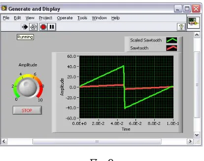
IV. RESULTS
This Proposed system simulated in a labviewsoftware as shown below
Fig. 9
Figure 9 shows the simulation of temperature control of steam using microcontroller arduino mega 2560 in labview software
V. CONCLUSION
An idea behind the proposed system is to control the temperature inside super heater and we can make set point to be at 535.c, a spray valve is to be used in the super heater header, and this can be controlled using micro controller arduino mega 2560 and this help to measure temperature and pressure efficiently and we can make simulation using lab view software.
REFERENCES
[1] http://www.arduino.cc/
[2]Arduino Mega Board information. Referred at: http://arduino.cc/en/Main/ArduinoBoardMega [3] Dr. K Srinivasan, Ashwati M Menon,
Sri Ramakrishna engineering college, Coimbatore,control Of Boiler Steam Temperature Using Different Control Stratagies © 2015 IJIRT | Volume 1 Issue 12 | ISSN: 2349-6002.
[4]PID Controller Parameters Tuning Based-on Satisfaction for Superheated Steam Temperature of Power Station Boiler,Published Online June 2014 in MECS (http://www.mecs-press.org/) DOI: 10.5815/ijitcs.2014.07.02.