MODELLING AXIAL RELOCATION OF FRAGMENTED FUEL
PEL-LETS INSIDE BALLOONED CLADDING TUBES AND ITS EFFECTS
ON LWR FUEL ROD FAILURE BEHAVIOUR DURING LOCA
Lars O. Jernkvist1, Ali R. Massih1,2
1
Quantum Technologies AB, Uppsala Science Park, SE-75183 Uppsala, Sweden
2
Division of Materials Science, Malmö University, SE-20506 Malmö, Sweden
ABSTRACT
Downward axial relocation of fuel pellet fragments may occur when overheated and internally over-pressurized cladding tubes of light water reactor fuel rods distend due to creep during a loss-of-coolant accident (LOCA). The relocation is of safety concern, since it changes the axial distribution of heat load along the rod and also has the potential to increase the amount of fuel material dispersed into the reactor coolant, should the cladding fail. Here, we present a computational model that calculates the fuel relocation on the basis of estimated fuel fragment size distributions and the calculated cladding distension along the fuel rod. The model has been implemented and fully integrated with the FRAP-TRAN-1.5 computer program, such that thermal feedback effects of fuel relocation on the axial redistribution of fuel mass, stored heat and power are accounted for in FRAPTRAN’s calculations of the fuel rod thermo-mechanical behaviour. The model has been validated against the IFA-650.4 integral LOCA test in the Halden reactor, Norway, which was done on a very high burnup UO2 fuel
rodlet and resulted in extensive fuel pellet pulverization, axial relocation and dispersal into the coolant. Our simulations of this test suggest that thermal feedback effects from axial fuel relocation are strong enough to significantly affect the dynamics of cladding ballooning and rupture, in spite of the short duration of these processes. Moreover, for the considered LOCA test, the axial relocation has a strong effect on the calculated peak cladding temperature and oxidation after rupture.
INTRODUCTION
shifted from the effects of fuel relocation on the local heat load to its effects on fuel dispersal upon cladding rupture. The fuel dispersal is a potential issue with regard to energetic fuel-coolant interaction, radiological consequences, criticality and long-term coolability of the material ejected into the coolant.
To our best knowledge, the first computational model for axial fuel relocation was presented at the 1983 SMiRT conference by Siefken (Siefken, 1983). This model, which was implemented in the SCDAP computer program for severe accident analyses, was based on experimental results and data available at that time. Since then, along with the more recent LOCA tests on high burnup fuel, various computational models for fuel relocation have been proposed and used for evaluations of the tests (Aounallah et al., 2006, Khvostov et al., 2007, Govers and Verwerft, 2014). A common feature of these later models is that they are used as post-processors to computer programs for thermo-mechanical analyses of fuel rods: the cladding distension along the fuel rod during the LOCA is calculated with these programs and used as input to subsequent calculations of fuel relocation. However, the relocation models are not integrated with the computer programs, which means that effects of fuel relocation on the axial redistribution of stored heat and power are not accounted for in the thermo-mechanical analyses of the rod. The reason for this lack of integration can be understood from the typical “1 ½ D” computational approach used in fuel rod analysis programs (Lassmann and van Uffelen, 2004). The term alludes to the fact that most computer programs of this kind represent the fuel rod by a stack of axial segments, and that the heat transfer and deformations in each segment are calculated by solving one-dimensional (radial) equations. Axial interaction between the segments is merely by coolant heat transfer, a common internal fuel rod gas pressure, and possibly axial forces from pellet-cladding mechanical interaction. Adding axial fuel relocation to these programs is nontrivial, since the relocation introduces a significant interaction between the axial segments with regard to the fuel rod temperature calculations. In addition, the temperature calculations in fuel rod analysis programs are done on the basis of a geometrical configuration with cylindrical fuel pellets surrounded by an annular, gas-filled, pellet-cladding gap. These conditions do not apply when axial fuel relocation occurs, since the cylindrical pellets collapse into a porous particle bed with crumbled fuel in ballooned regions of the fuel rod.
In this work, we present a relocation model that is fully integrated with the FRAPTRAN-1.5 fuel rod analysis program (Geelhood et al., 2014). Hence, in contrast to hitherto presented relocation models for fuel rod analysis programs, the model considers thermal feedback effects from the fuel relocation. It also uses submodels to calculate the packing fraction and effective thermal conductivity of particle beds formed by crumbled fuel in ballooned regions of the fuel rod, based on the estimated state of fragmentation and pulverization of the fuel pellets.
MODEL DESCRIPTION
Our model is based on two postulated prerequisites for axial fuel relocation.Firstly, a sufficient pellet-cladding gap is required for fuel fragments to detach from the surrounding pellet-cladding and move downward. This threshold radial gap size, gth, is set to 0.2 mm in our model, based on results from recent LOCA simulation experiments in Studsvik, Sweden, and Halden, Norway. Post-test examin-ations of test rodlets used in these experiments show that the local cladding hoop strain must exceed about 5 % to allow fuel fragment separation and axial movement (Raynaud, 2012, Oberländer and Wiesenack, 2014). No observable dependence on fuel pellet burnup is reported for this threshold strain over the investigated burnup range (44–92 MWd/kgU). The threshold pellet-cladding gap size used in our model corresponds to a cladding hoop strain of about 4.5–5.0 %, depending on the cladding tube dimensions. More experimental data are needed to determine whether the threshold gap size gth
Secondly, the cladding distension along at least one axial segment of the discretized fuel rod must be sufficient to accommodate relocated fuel fragments in a disordered (crumbled) configuration, which is assumed to contain a lot more void volume than the original, pellet-like configuration. In a specific axial segment of the fuel rod, henceforth referred to by subscript k, the fuel configuration is defined by the packing fraction of fuel fragments,
k f k
k ! V V
" . (1)
Here, Vkf is the volume occupied by fuel fragments and Vk is the total volume enclosed by the cladding tube in the k:th segment. In an axial segment of length Lk, this volume is
2
cik k
k L R
V !# ,
whereRcikis the cladding inner radius. Under normal reactor operation, "k is close to unity, since the fuel fragments are then densely packed and retained in the original, cylindrical configuration of the pellets, where the void volume is made up essentially of pellet dishes, cracks and possibly a narrow pellet-cladding gap. When the cladding tube distends under LOCA, the gap gradually widens and may reach a size that makes the fuel pellet column collapse. The fuel fragments then move radially outward and turn into a disordered pattern with "k significantly lower than unity. Here, we make the
assumption that local collapse of the fuel pellet column in an axial segment occurs when more fuel can be accommodated in a crumbled configuration than in the original, pellet-like, configuration. This condition on fuel pellet column collapse can be written as
i k M
k m
m $ , (2)
where mkM ! "k%fVk, with %f being the density of the fuel material, is the fuel mass in the k:th axial segment in case it is completely filled with crumbled fuel, and mik is the initial (as-fabricated) fuel mass in the segment. We treat the packing fraction of crumbled fuel as a model parameter, which is correlated to the fragment size distribution. More specifically, we assume that the crumbled fuel consistsof two different size classes of fragments: The first class includes large (> 1 mm) fragments, created by thermal stresses in the fuel during normal operation, whereas the second class comprises fine (< 0.2 mm) fragments, created during the LOCA by overheating high burnup fuel. The second fragment class thus exists only in high burnup fuel after overheating, and a recently proposed empirical “pulverization threshold” (Turnbull et al., 2014) is in our model used for estimating the mass fraction of small fuel fragments, based on the calculated distributions of burnup and temperature in the fuel. The fine fuel fragments are important, since they may effectively fill up voids between the mm-size fragments and thereby significantly increase the overall fragment packing fraction. This is illustrated in Fig. 1, which shows the calculated fuel fragment packing fraction of crumbled fuel versus the relative amount of small fragments, assuming four different sizes for the large fragments. The methods used for calculating "k from the estimated state of fuel fragmentation and pulverization
are described in (Jernkvist et al., 2015, Jernkvist and Massih, 2015).
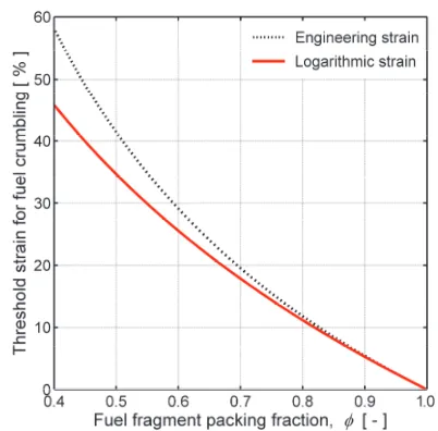
The condition defined by Equation (2) will preclude axial relocation until the cladding tube in some axial segment reaches a threshold deformation, roughly given by "kRcik2 (t)&Rcik2 (0), where the right-hand-side quantity is the as-fabricated cladding inner radius. In terms of cladding hoop logarithmic (true) strain, (''(t)& ln(Rcik(t)/Rcik(0)), the condition in Equation (2) can thus be written
2 ) ( ln )
( )
(t (th t "k
('' $ '' & ) , (3)
Fig. 1: Calculated packing fraction of crumbled fuel vs. relative amount of small fragments
from pulverized high burnup fuel.
Fig. 2: Cladding threshold strain for fuel pellet column collapse and onset of axial fuel
relo-cation, calculated through Equation (3).
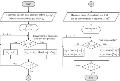
The axial fuel relocation is calculated by a fairly simple algorithm, which comprises two loops over the N axial segments of the discretized fuel rod; see Fig. 3. Henceforth, the segment numbering is assumed to run bottom-up, and subscript k refers to the k:th segment from the bottom. We consider a time step that starts at time to, and assume that the fuel mass in each axial segment is known for this
point in time. This mass is henceforth denoted mok, whereas mk denotes the sought fuel mass at end of the time step.In the first loop, the aforementioned requirement on a minimum pellet-cladding gap size for fuel mobility is used for calculating the amount of fuel, mkr, that each axial segment may receive from higher elevation segments. All fuel in an axial segment, except for a small residual fraction xr, is allowed to fall down if gk $ gkth. The residual fraction represents small fuel fragments that are
bonded to the cladding inner surface. Next, the condition from Equation (2) is applied in the second loop to “fill” ballooned axial segments, according to the calculated crumbled fuel packing fraction and cladding deformation that applies to the segment. Filling is possible only if sufficient moveable fuel is available above the segment, as determined in the first loop. Conditions are also imposed so that the total fuel mass in the rod is conserved and upward relocation precluded. The upper and lower limits for the sought end-of-timestep fuel mass mk in Fig. 3 are given by
*
*
) ! ! ) ! 1 1 1 k j j k j o j Lk m m
m , (4)
*
*
) ! ! ) + ! 1 1 1 k j j k j o j r k Uk m m m
m . (5)
significantly reduced, while gas-filled voids open up between the disorderly stacked fuel fragments. Since the volume fraction of gas is typically 20–30 %, the macroscopic thermal conductivity of the crumbled fuel in the balloon may be much lower than that of solid fuel material. This conductivity degradation is accounted for in our model (Jernkvist and Massih, 2015).
Fig. 3: Computational algorithm. First loop over the N axial segments determines mass of relocatable fuel, mkr. Second loop updates local fuel mass, mk. All variables are defined in the running text.
MODEL VERIFICATION AND VALIDATION
Model Verification
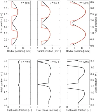
The correctness of the computational algorithm in Fig. 3 has been verified by applying the relocation model to several test cases (Jernkvist and Massih, 2015). For illustration, we consider here a test case, in which a hypothetical axial profile for the cladding deformation is prescribed along a full-length fuel rod and the resulting fuel relocation is calculated as a function of time as the cladding distension is postulated to increase. The active length of the fuel rod is assumed to be 3.60 m, and the fuel pellet diameter is 9.0 mm. The fuel is assumed to be in a state such that a fragment packing fraction of 0.75 is obtained after fuel crumbling. For simplicity, this packing fraction is presumed to be independent of space and time. The fuel rod is discretized into 36 equal-length axial segments, and the prescribed cladding deformation is defined by
) / 2 sin( 10 0 . 2 10 5 . 4 ) ,
( 3 5 a
ci t z t z L
R ) ) #
, + ,
! , (6)
where Rci is the inner radius of the cladding and z/La is the relative position along the active length (La)
of the fuel rod. The time t is in units of seconds. The cladding deformation (evolution of Rci) is shown
calculated fuel pellet radius. From this line, it is easily seen where the cladding deformation is large enough for collapse of the fuel pellet column to occur, i.e. where the condition mkM $mik is satisfied.
Fig. 4: Top panel shows deformation pattern. Solid black line: Cladding inner radius, as defined by Equation (6). Dotted red line: Calculated fuel pellet radius, indicating regions where collapse of the fuel pellet column may occur. Bottom panel shows calculated space-time variation in fuel mass.
fuel mass; the fuel just passes by on its way down, virtually in its original pellet-like configuration. This behaviour is confirmed by experiments (Oberländer and Wiesenack, 2014).
Model Validation Against the Halden IFA-650.4 LOCA Test
The Halden IFA-650.4 LOCA test was conducted on a 480 mm active length rodlet that had been sampled from a full length UO2 fuel rod with Duplex-type Zircaloy-4 cladding after seven reactor
cycles of operation in a commercial pressurized water reactor. The test is well suited for model validation, since it was carried out on an extensively instrumented fuel rodlet with very high fuel burnup (92.3 MWd/kgU) and resulted in cladding ballooning and burst, as well as significant axial fuel relocation and dispersal of pulverized fuel into the coolant. The IFA-650 test rig and typical testing procedures are described in (Wiesenack, 2013, Kolstad et al., 2011). In short, the test rodlet is instrumented and placed in the centre of the rig, which in turn is placed in one of the experimental channels of the Halden test reactor. The rodlet is surrounded by an electrically heated shroud and a pressure flask. The latter is connected to a water loop that may be depressurized into a large blowdown tank to simulate a LOCA. During most of the IFA-650.4 test, the linear heat generation rates of the rodlet and heater were held nearly constant at about 1.0 and 1.5 kW/m, respectively. The test was terminated by reactor scram 617 s after initiation of blowdown, which defines the starting point of the test (henceforth referred to as t = 0). Cladding rupture was detected at t = 336 s.
The first 500 seconds of the IFA-650.4 LOCA test were modelled with our extended version of FRAPTRAN-1.5. Since the power was held constant during this period and no water was sprayed into the test rig, the thermo-hydraulic boundary conditions for the rodlet were fairly simple and could be derived from temperatures and pressures measured in different parts of the test rig; details on the methodology are given in (Jernkvist and Massih, 2015). The initial conditions of the rodlet were determined by modelling the pre-test operating life of the fuel rod sample by use of the FRAPCON-3.5 program (Geelhood and Luscher, 2014). Based on the fuel operating life, the packing fraction of crumbled fuel is expected to be 0.72 in ballooned regions of the test rodlet. It should be noted that our extended version of FRAPTRAN-1.5 includes not only the axial fuel relocation model described here, but also a set of models that treat cladding high temperature metal-water reactions, solid-solid phase transformation, creep and failure in a unified fashion (Manngård and Massih, 2011). All computations were carried out with best-estimate models, but the cladding high temperature creep rate was scaled by a constant to match the calculated and measured time to cladding rupture. The test was simulated twice, with and without the model for axial fuel relocation, in order to assess the importance of the relocation to the thermo-mechanical behaviour and high temperature degradation of the test rodlet. Other models were identical for the two cases.
The calculated time to cladding rupture was 335.2 s with fuel relocation and 352.1 s without, which means that the calculated time to rupture was shortened by no less than 17 s as a result of thermal feedback effects from fuel crumbling and relocation. These feedback effects are illustrated in Fig. 6, which shows the cladding outer surface temperature versus axial position, calculated with and without consideration of axial fuel relocation.
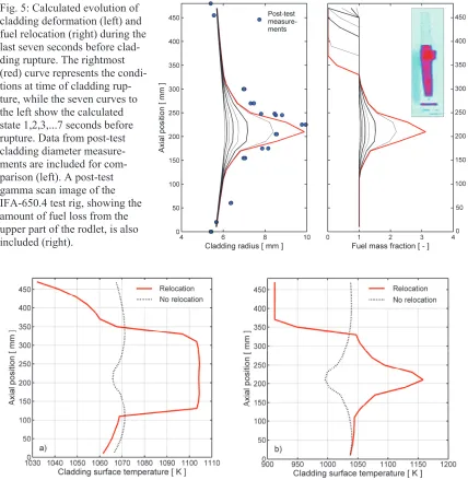
Fig. 5: Calculated evolution of cladding deformation (left) and fuel relocation (right) during the last seven seconds before clad-ding rupture. The rightmost (red) curve represents the condi-tions at time of cladding rup-ture, while the seven curves to the left show the calculated state 1,2,3,...7 seconds before rupture. Data from post-test cladding diameter measure-ments are included for com-parison (left). A post-test gamma scan image of the IFA-650.4 test rig, showing the amount of fuel loss from the upper part of the rodlet, is also included (right).
Fig. 6: Calculated cladding outer surface temperature vs. axial position at time of cladding rupture (a) and at time t = 500 s (b). Calculations were made with and without consideration of fuel relocation.
instantaneous cladding temperature increase in the balloon just after fuel crumbling is caused not so much by the local increase of fuel mass as such, but by closure of the pellet-cladding gap as the fuel pellet column collapses and hot fuel fragments come into contact with the cladding inner surface. The local increase of fuel mass in the balloon results in only minor thermal feedback effects before
cladding rupture, but it has significant impact on the local cladding temperature and oxidation rate
after rupture, as shown by Fig. 6b. The temperature peaking shown in Fig. 6b has a strong localization effect on cladding oxidation, and the calculated peak value for equivalent cladding reacted (ECR) during the IFA-650.4 LOCA test is doubled when axial fuel relocation is considered in the simulations (Jernkvist and Massih, 2015).
CONCLUSIONS AND OUTLOOK
In conclusion, some unique features of the presented relocation model should be emphasized. Firstly, the model is fully integrated with the equations used for calculating the space-time variation of fuel and cladding temperature in FRAPTRAN-1.5. This means that thermal feedback effects from the axial redistribution of power and stored heat that the fuel relocation brings about are fully accounted for in FRAPTRAN’s calculations of the fuel rod thermo-mechanical behaviour. Also, the changes in fuel geometry and effective thermal conductivity caused by collapse of the fuel pellet column into a porous particle bed of crumbled fuel in ballooned regions of the fuel rod are considered in the calculations. Our simulations of the Halden IFA-650.4 LOCA test suggest that these thermal feedback effects from fuel crumbling and relocation are strong enough to significantly affect the dynamics of cladding ballooning and rupture, even though the calculated duration of these processes is no more than 7–8 s. Moreover, for the considered test, the axial relocation has a strong effect on the calculated peak cladding temperature and oxidation after cladding rupture. Secondly, the packing fraction of crumbled fuel in ballooned regions of the fuel rod is in our model estimated from the state of fuel fragmentation and pulverization. This packing fraction is a key model parameter that controls the degree of fuel relocation, given the deformed configuration of the cladding tube. It also makes an impact on the concentration of heat load to ballooned regions.
Finally, it should be remarked that the presented relocation model may be extended for predicting the fuel mass that would be ejected into the coolant upon cladding rupture at any axial position. Such predictions must consider that spacer grids act as choke points for axial fuel relocation, thereby limiting the relocatable and dispersible amount of fuel. Also, it is necessary to correlate the amount of ejected fuel to the fuel fragment size distribution and to the expected area of the cladding breach. The latter would require a significant experimental effort in order to widen the available database.
ACKNOWLEDGEMENT
This research was supported by the Swedish Radiation Safety Authority (SSM) as part of the IAEA Coordinated Research Project FUMAC – Fuel Modelling in Accident Conditions.
REFERENCES
Broughton, J. M., Mason, R. E., McCardell, R. K. and MacDonald, P. E. (1981). PBF LOCA test series: Test LOC-3 and LOC-5 fuel behavior report, Report NUREG/CR-2073, U.S. Nuclear Regulatory Commission, Washington, DC, USA.
Flanagan, M., Askeljung, P. and Puranen, A. (2013). Post-test examination results from integral, high-burnup, fueled LOCA tests at Studsvik Nuclear Laboratory, Report NUREG-2160, U.S. Nuclear Regulatory Commission, Washington, DC, USA.
Geelhood, K. J. and Luscher, W. G. (2014). FRAPCON-3.5: A computer code for the calculation of steady-state, thermal-mechanical behavior of oxide fuel rods for high burnup, Report NUREG/CR-7022, Vol. 1, Rev. 1, Pacific Northwest National Laboratory, Richland, WA, USA. Geelhood, K. J., Luscher, W. G. and Cuta, J. M. (2014). FRAPTRAN-1.5: A computer code for the
transient analysis of oxide fuel rods, Report NUREG/CR-7023, Vol. 1, Rev. 1, Pacific Northwest National Laboratory, Richland, WA, USA.
Govers, K. and Verwerft, M. (2014). "Simulation of ballooning and relocation in the Halden LOCA
tests with FRAPTRAN", Enlarged Halden Programme Group Meeting, Røros, Norway,
September 7-12, 2014. OECD Halden Reactor Project, Halden, Norway
Jernkvist, L. O. and Massih, A. R. (2015). Models for axial relocation of fragmented and pulverized fuel pellets in distending fuel rods and its effects on fuel rod heat load, Report 2015:NN, Swedish Radiation Safety Authority, Stockholm, Sweden.
Jernkvist, L. O., Massih, A. R. and Alvestav, A. (2015). "Axial relocation of fragmented and pulverized fuel and its effects on fuel rod heat load during LOCAs", 2015 International Fuel Performance Meeting (TopFuel-2015), Zürich, Switzerland, September 13-17, 2015.
Karb, E. H., Prüssmann, M., Sepold, L., Hofamann, P. and Schanz, G. (1983). LWR fuel rod behavior in the FR2 in-pile tests, simulating the heatup phase of a LOCA, Report KfK-3346, Kern-forschungszentrum Karlsruhe, Karlsruhe, Germany.
Khvostov, G., Romano, A. and Zimmermann, M. A. (2007). "Modeling the effects of axial fuel relocation in the IFA-650.4 LOCA test", Enlarged Halden Programme Group Meeting, Storefjell, Norway, March 12-15, 2007. OECD Halden Reactor Project, Halden, Norway.
Kolstad, E., Wiesenack, W., Oberländer, B. C. and Tverberg, T. (2011). "High burn-up fuel behaviour under LOCA conditions as observed in Halden experiments", IAEA Technical Meeting on Fuel Behaviour and Modelling under Severe Transient and Loss-of-Coolant Accident (LOCA) Conditions, Mito, Japan, October 18-21, 2011. IAEA, Vienna, Austria, TECDOC-CD-1709. Lassmann, K. and van Uffelen, P. (2004). The structure of fuel rod codes, Report EUR 21400 EN,
European Commission, Directorate General, Joint Research Centre, Karlsruhe, Germany.
Manngård, T. and Massih, A. R. (2011) "Modelling and simulation of reactor fuel cladding under loss-of-coolant accident conditions", Journal of Nuclear Science and Technology 48(1), pp. 39-49. Oberländer, B. C. and Wiesenack, W. (2014). Overview of Halden reactor LOCA experiments (with
emphasis on fuel fragmentation) and plans, Report IFE/KR/E-2014/001, Institute for Energy Technology, Kjeller, Norway.
Raynaud, P. A. C. (2012). Fuel fragmentation, relocation and dispersal during the loss-of-coolant accident, Report NUREG-2121, U.S. Nuclear Regulatory Commission, Washington, DC, USA. Siefken, L. J. (1983). "Axial fuel relocation in ballooning fuel rods", 7th International Conference on
Structural Mechanics in Reactor Technology (SMiRT-7), Chicago, IL, USA, August 22-26, 1983. Turnbull, J. A., Yagnik, S., Noirot, J., Walker, C. T., Hallstadius, L., Waeckel, N. and Blanpain, P.
(2014). "An investigation into fuel pulverization with specific reference to high burnup LOCA",
Enlarged Halden Programme Group Meeting, Røros, Norway, September 7-12, 2014. OECD Halden Reactor Project, Halden, Norway.
Wiesenack, W. (2010). Safety significance of the Halden IFA-650 LOCA test results, Report NEA/CSNI/R(2010)5, OECD Nuclear Energy Agency, Paris, France.