Transactions of the 17th International Conference on Structural Mechanics in Reactor Technology (SMiRT 17)
Prague, Czech Republic, August 17 –22, 2003
Paper # G02-2
Problems of Underclad Type Defects in Reactor Pressure Vessel Integrity
Evaluation
D. Lauerova1, M. Brumovsky1, P. Simpanen2, J.Kohopaa3
1 Nuclear Research Institute Rez plc, Rez, Czech Republic 2 POLARTEST Ltd., Finland
3 FORTUM Nuclear Services Ltd.,Helsinki, Finland
ABSTRACT
Underclad type defects are becoming important with the application of non-destructive methods qualification for in-service inspection of reactor pressure vessels. This type of defect may be included into reactor pressure vessel integrity assessment as one of the postulated defect types, with its shape and size depending on results of the qualification.
Postulated defect of underclad type represents a complicated calculation case from fracture mechanics point of view due to the fact that part of crack front is lying in close vicinity of material interface and problems with evaluation of J-integral may arise. Therefore, experiments on semi-large scale specimens are needed to validate the methodology of evaluating the underclad cracks. Instrumentation of such experiments should be at high level to provide as much information as possible on possibly occurring crack growth.
In NRI Rez 16 experiments on specimens with test section of 70x100 mm were performed, in co-operation with FORTUM Nuclear Services Ltd. The specimens were manufactured from reactor pressure vessel of WWER-440/V-213 type materials, i.e. from base metal and/or weld metal. One half of specimens were uncladded, containing through or semi-elliptical crack, and the second half of specimens contained underclad crack, again of through or semi-elliptical type. Materials were tested in as-received as well as aged condition, the latter representing the RPV end-of-life state.
In the paper, results of experiments and their evaluation using different sensitivity type calculations are presented – effects of residual stresses, strain gauge location and direction of crack propagation were examined.
KEY WORDS
:
underclad crack, reactor pressure vessel, cleavage, J-integral, fracture toughness, pop-in, cladding, residual stresses, experiment evaluation, finite element method, SYSTUS.INTRODUCTION
Within the PHARE Project 2.01.95 "Integrity Assessment of VVER 440/213 Reactor Pressure Vessels" and in cooperation with Fortum Ltd., a series of 16 large scale experiments on beams from base and weld metals in initial and aged condition was performed in Nuclear Research Institute Řež plc. Both cladded and uncladded beams were tested.
The experiments were performed with the goal to obtain semi-large scale experimental data related to assessment of integrity of reactor pressure vessel (RPV), i.e. values of fracture toughness KJc, and to compare
them with results of standard (small scale) tests. The effects of crack depth, specimen size and cladding were intended to be examined.
Four types of materials were tested: base metal of RPV WWER-440, i.e. ferritic steel of 15Kh2MFA grade (Cr-Mo-V type), in initial and aged condition, and weld metal in initial and aged condition. Under aged condition the simulated material degradation state close to the end of pressure vessel life is understood.
Evaluation of cladded specimens is substantially more difficult than evaluation of the uncladded ones due to several facts: (1) cladded specimens may (and usually do) undergo pop-ins during loading, (2) residual stresses resulting from cladding procedure have to be modelled, (3) experimental force vs. strain curves for cladded specimens exhibit a “change in slopes” in their linear parts which is not present e.g. in experimental force vs. CMOD curves for uncladded specimens.
Values of J-integral associated with first pop-ins (usually several pop-ins occurred within one experiment) were determined for selected specimens. For one of the specimens also the J-values associated with 2nd pop-in
and final failure were determined.
GEOMETRICAL AND MATERIAL CHARACTERISTICS OF CLADDED BEAMS
Seven cladded beams containing semi-elliptical or through underclad crack were subject to four point bending, at temperatures near to reference temperature T0 [1]. Chemical composition of base material of RPV
VVER-440 is seen in Table 1. Brief overview of geometrical as well as material characteristics, including test temperatures, is attached in Table 2. The dimensions (in mm) of beams (before cladded) were 70 x 100 x 670. The cladding thickness was 8 mm, so that total “thickness” of cladded specimens was 78 mm.
Table 1. Chemical composition of steel 15Kh2MFA (mass%)
C S Mn Cr Mo V Ni
0.13÷0.18 0.17÷0.37 0.3÷0.6 2.5÷2.8 0.6÷0.8 0.25 ÷ 0.35 <0.4
Table 2. Geometrical and material characteristics of cladded specimens
Specimen
No. materialtype materialcondition crack type crack depth a,resp. a x 2c [mm]
Test temperature [oC]
Reference temperature T0 [oC]
Tensile Strength [MPa] PHAV202
PHAV104 basebase initialinitial semi-ellipt.through 15.5 x 48.919 - 118-112 -118 -118 683683 PHBV202
PHBV104 basebase agedaged semi-ellipt.through 9.8 x 24.515.7 + 20- 40 5 5 875 841
PH1CV102 weld initial semi-ellipt. 13.1 x 49.9 +21 0 519
PH1CV104 weld initial through 20.1 + 15 0 519
PH3DV102 weld aged semi-ellipt. 9.5 x 26.2 +54 73 632
EXPERIMENTAL RESULTS
In the experiments, values of total force, load line displacement and strains were recorded. The strain gauge was located on the cladding surface, just above the crack (on the symmetry plane of the specimen), and strain in the direction perpendicular to the crack plane was measured.
Due to lack of space not all load vs. LLD/strain curves obtained from experiments can be presented in this paper. Only load vs. strain curves of selected specimens, important also from point of view of FE evaluation, are attached in Figs 1-4. In the experimental records two interesting phenomena were identified (as illustrated in Figs. 1-4): (1) each of tested specimens underwent one or more pop-ins, (2) for some of the specimens (PHAV104, PHBV202, PHBV104, PH1CV102, PH1CV104), the change in slopes in linear parts of force vs. strain curves may be seen; for other specimens (PH3DV102 and PHAV202) no change in slopes is apparent. Character of the changes in slopes is not the same for all specimens experiencing it: for specimens PHBV104, PH1CV102, PHAV104 and PHBV202 the strains are increasing faster beyond the point of change compared to their increase before this point (Figs. 1-3), while for specimen PH1CV104 the strains are increasing more slowly beyond the point of change compared to their increase before this point (Fig. 4).
It is assumed that pop-ins correspond to crack growth, although this hypothesis has not been fully proved yet. In any case, based only on the experimental load vs. LLD/strain records, it cannot be decided whether pop-in represents crack propagation into cladding or into base metal. In some cases fractographical analysis may be of some help in answering this question. This was the case of specimen PH1CV102, where only one pop-in occurred. Fractographical analysis of this specimen showed that crack propagated into base metal (and arrested).
All specimens failed by cleavage, no ductile tearing prior to cleavage was observed.
NUMERICAL ANALYSIS OF EXPERIMENTAL DATA
PHAV104 an additional 2D FE model was created. The 2D model was used to facilitate simulation of the crack growth (pop-ins) as well as numerical testing of the effects of residual stresses (stress free temperature effects) on the shape of force vs. strain curve. Attention was also paid to the possible effect of location of the strain gauge on force vs. strain curve, since it was found that the calculated force vs. strain curve is very sensitive to the location where the strain was measured.
Values of J-integrals were determined using fracture mechanics 2D or 3D post-processing module of SYSTUS based on G-θ method [2] or 2D post-processing module based on Rice’s contour integral.
Quadratic isoparametric elements were used for construction of both 3D and 2D meshes, with element size near the crack front of 3D mesh varying within range 0.4 - 0.9 mm. Element size of 2D mesh was 0.2 mm.
In both 2D and 3D FE models the elastic-plastic behaviour of specimens was modeled using flow theory of plasticity with von Mises yield surface and isotropic strain hardening. Large strains (updated Lagrangian formulation) were used.
To simulate the effects of cladding procedure (residual stresses), volumic deformation corresponding to cooling down from stress free temperature to the appropriate test temperature was applied in the first step of loading. Volumic deformation for cladding differs from that one of base material due to different thermal expansion coefficients. Thus, different volumic deformations were applied in elements corresponding to cladding and base metal. Since there is some uncertainity in determination of stress free temperature, various stress free temperatures were applied and their effects were studied. After applying volumic deformation, loading by 4-point bending was simulated.
EVALUATION OF TESTS
Problems of Numerical Simulation of Experimental Records
In what follows, three effects were examined in connection with problem of numerical simulation of experimental records (force vs. LLD/strain curves): (1) effect of crack growth, (2) effect of residual stresses, (3) effect of strain gauge location.
Ad (1) – effect of crack growth: A “pop-in study” was performed on 2D model of specimen PHAV104
with the goal to simulate the crack growth of the specimen. In the force vs. strain records for this specimen two significant pop-ins may be seen (Fig. 1). Neither from the experimental records nor from fractographical analysis it can be determined whether the crack propagated first into the cladding and second into base metal or inversely, or whether both propagations were into the same metal (cladding or base metal). Moreover, neither the amounts of crack propagations can be recognized from experimental records. Consequently, only some numerical simulations may be performed to shed some light on the situation.
For stress free temperature Tf = 600 ºC, the following 5 variants of crack propagation were considered
(Table 3). In all these variants, either mean value of local strains of 3 nodes lying within distance 2.91 mm from symmetry plane or local strain in 1 node lying on symmetry plane was taken as „strain“.
Table 3. Crack propagation variants simulated numerically
1st pop-in into 2nd pop-in into
Variant No.
cladding base metal cladding base metal
Strain
1 2 mm - - 2 mm Mean of strains in 3 nodes
2 2 mm - 1 mm - Mean of strains in 3 nodes
3 - 2 mm 2mm - Mean of strains in 3 nodes
4 2.5 mm - - 3mm In 1 node on symmetry plane
5 2.5 mm - 2.5 mm - In 1 node on symmetry plane
The results of FE simulations as well as experimental curve are seen in Fig. 1. From this figure it is seen that satisfying accordance between calculation and experiment was not reached, for any variant.
On the other side, the most important finding is that different numerical variants of crack growth produce very similar force vs. strain curves. It follows from this fact that neither numerical simulation can significantly help in answering the question where the crack propagated during pop-in. The only specimen for which this question was answered was specimen PH1CV102. This specimen underwent only one pop-in (Fig. 3) and crack propagation occurred into weld metal as seen (even visually) from the fracture surface.
Ad (2) – effect of residual stresses: Effect of residual stresses, which means actually effect of stress free temperature Tf, was studied on 2D model of specimen PHAV104. Different stress free temperatures Tf = 350 ºC,
plane. From this figure it is seen that effect of stress free temperature exists. Simultaneously, it is seen that good accordance between calculated and experimental force vs. strain curves cannot be reached by only changing the stress free temperature.
Ad (3) – effect of strain gauge location: As may be seen from Figs. 1 and 2, numerical simulations described so far did not produce satisfying accordance between calculated and experimental force vs. strain curves, in particular between their linear parts. After detailed study of stress and plastic zone distribution during loading (performed for specimen PH1CV102) a new possibility appeared that might explain the discrepancy. This new possibility consists in considering effect of strain gauge location.
The strain gauge size was 3.2 mm. In what follows, we understand under “experimental strain” the deformation of a segment of length equal to strain gauge size, i.e. 3.2 mm. The problem was examined on a 3D model of specimen PH1CV102. The region on the cladding surface above the crack is a region of large deformation gradient at medium and higher levels of loading. In this region, plastic deformation band arises at certain level of bending loading. (Due to lack of space we do not attach plot of deformation band here.) The region where the deformation band reaches the cladding surface is, in case of specimen PH1CV102, detached from the symmetry (crack) plane, about 6-9 mm. It is clear that several mm detached location of strain gauge from the symmetry plane may have as a consequence increasing of strain rate in this region at certain level of loading (corresponding to developing of deformation band on the cladding surface). Different detached locations of strain gauge were numerically examined; the results are seen in Fig. 3. In this figure, numbers in parentheses mean distance of left and right strain gauge end-point respectively from the symmetry plane. From this figure it seen that location (3.63, 6.83) yields a very good accordance between the experimental and calculated force vs. strain curves. (In this case, center of strain gauge is located 5.23 mm from the symmetry plane.) This result suggests that "change in slopes" in linear parts of experimental force vs. strain curves is associated with developing of deformation bands on the cladding surface in combination with the detached (eccentric) strain gauge location. This hypothesis is further supported by experimental record for specimen PH1CV104 (Fig. 4) where change in slopes in linear part of the force vs. strain curve is also seen, but it is of opposite sense than in case of specimen PH1CV102. According to our hypothesis the strain gauge for this specimen was situated on (or very close to) the symmetry plane where the strain rate decreases when deformation band develops.
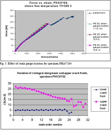
Effects of both strain gauge location and stress free temperature Tf were examined also for specimen
PHAV104 (results of 3D model). As may be seen from Fig. 5, good accordance between calculated and experimental force vs. strain curves was reached for T0 = 500 ºC and strain gauge location (0.8, 4), i.e. strain
gauge center located in distance of 2.4 mm from the symmetry plane.
General Experiences from Determination of J-integral Values
For four specimens (PHAV104, PHBV202, PH1CV102 and PH3DV102) the J-values along lower (for crack propagation into base/weld metal) as well as upper (for crack propagation into cladding) crack fronts were calculated. In most cases, the G-theta method [2], both in 2D and 3D, was used for calculation of J-integral. In other words, in what follows we do not distinguish between J and G, i.e. when G-value is calculated we put J=G. In some cases, also the Rice contour integral method was used for calculation of J, in particular, in the case of lower crack front in 2D calculations. For the upper crack front, the Rice contour integral method is not relevant due to vicinity of material inerface.
Since in our case the mesh was not too much refined in the vicinity of upper crack front, the J(G)-values presented in this paper for the upper crack front can be considered only as very approximate. Globally, the experiences with calculations of J(or G)-values may be described as follows: No problem arises when J-values along lower crack front are determined, J-values are path- (for 2D Rice method) or parameters- (for 2D and 3D θ method) independent. But when J-values along upper crack front are calculated, then, in 2D calculations, G-values were parameter-dependent, and in 3D calculations, in some cases the parameter dependence was not so strong, therefore some values of J (=G) obtained from 3D calculations using G-θ method are attached.
Evaluation of Individual Specimens
In the following Table 4, the calculated J (and K)-values associated with pop-ins and/or final failure for 4 variants (defined in Table 3) of crack growth for specimen PHAV104 are summarized.
In Fig. 6 - 7, variations of J-integral along both lower and upper crack fronts before 1st pop-in for specimens
PHAV104 and PH1CV102 are plotted. From these figures it is seen that in all cases the J-values along upper crack front are significantly higher than J-values along lower crack fronts. According to opinion of the authors, it cannot be concluded from these facts that crack propagation into cladding (at 1st pop-in) is more likely than into
On the whole, taking into account also preliminary results obtained for underclad cracks within NESC-IV project, it seems that this is a typical situation for the underclad cracks: J-values along upper crack front are significantly higher than J-values along lower crack front. Nevertheless, at least for specimen PH1CV102 (Fig. 3) it was proved that this pop-in was into weld metal (i.e. not into cladding), despite the fact of significantly higher values of J along upper crack front (Fig. 6).
Table 4. Calculated J-integral values for specimen PHAV104 (assuming stress free temperature Tf = 600 ºC)
Jc
[kJm-2] K[MPamc 1/2] J[kJmc -2] [MPamKc 1/2] J[kJmc -2] K[MPamc 1/2]
before 1st pop-in before 2nd pop-in before fracture
2D, Variant 1 1.6 19.2 11.5 51.5 16.5 61.7
2D, Variant 2 1.6 19.2 11.5 51.5 20.5 68.8
2D, Variant 3 1.6 19.2 5.5 35.6 15.6 60.0
2D, Variant 4 1.6 19.2 12.8 54.3 17.0 62.6
G calculated along lower crack front
3D model 1.3 17.3 - - -
-G calculated along
upper crack front 3D model 25.5 76.7 - - -
-CONCLUSIONS
Performed FE analyses showed that evaluation of experiments with underclad cracks brings non-standard problems, compared to evaluation of uncladded specimens with surface cracks. The following experiences were gained from the performed evaluations:
Experimental records of cladded specimens contain pop-ins and ″change in slopes″ in linear parts of the load vs. strain curves. Pop-ins are assumed to be associated with crack propagation (and arrest). As far as ″changes in slopes″ are concerned, it was shown that they might be consequence of arising of a deformation band on the cladding surface, in combination with eccentric location of strain gauge on the cladding surface.
It was also shown that effect of residual stresses may be simulated as effect of stress free temperature, using different volumic deformations of cladding and base/weld metal that correspond to cooling down from the stress free temperature to the test temperature.
Pop-in study revealed that based only on numerical simulations of crack growth, it cannot be decided where the crack propagated during pop-in, whether into cladding or into base/weld metal. For more effective evaluation of experiments with underclad cracks, additional information from experiments is needed, which includes primarily more sophisticated experimental set up or more sophisticated control of the experiments.
At evaluation of experiments with underclad cracks, problems with determination of J(or G)–values along upper crack front (near to or on material interface) may arise. In general, for determination of J (G) along upper crack front the G-theta method (both in 2D or 3D) may be used, provided that the mesh is sufficiently refined near the upper crack front. Significantly higher values of J (G) typically obtained for the upper crack front compared to the lower crack front do not imply necessarily that the crack will propagate into the cladding (even disregarding the fact that the ″fracture toughness for the material interface″ is not known), and may be associated with loss of constraint in the vicinity of upper crack front.
All summarized items suggest that underclad cracks need still more investigations focused primarily on examinations of pop-ins, i.e. more information from experiment is needed about where the crack propagates. This can be ensured by more sophisticated experimental set-up and/or more sophisticated conducting of the experiments.
REFERENCES
[1] ASTM Standard E 1921 – 97. Standard Test Method for Determination of Reference Temperature T0, for
Ferritic Steels in the Transition Range.
[2] Mialon, P.: "Calcul de la derivée d’une grandeur par rapport a un fond de fissure par la méthode θ". E.D.F. – Bulletin de la Direction des Etudes et Recherche – Série C-1988
Force vs. strain, PHAV104
simulation of crack growth
0 50 100 150 200 250 300 350
0 1000 2000 3000 4000 5000 6000
microstrains
force [kN]
experiment
FE variant 1
FE variant 2
FE variant 3
FE variant 4
FE variant 5
Fig.1. Pop-in study for specimen PHAV104 (in 2D)
Force vs. strains, specimen PHAV104
0 50 100 150 200 250 300 350
0 1000 2000 3000 4000 5000 6000
microstrains
force [kN]
experiment
FE, Tf=350 C
FE, Tf=400 C
FE, Tf=600 C
Force vs. strain, specimen PH1CV102
Tf = 350 C
0 100 200 300 400 500 600
0 2000 4000 6000 8000 10000 12000 14000
strain [microstrains]
force [kN]
experiment
strain gauge location (-1.6, 1.6)
strain gauge location (0, 3.2)
strain gauge location (3.63,6.83)
Fig. 3 Effect of strain gauge location for specimen PH1CV102, for stress free temperature Tf = 350 C
Force vs. strain, specimen PH1CV104
0 50 100 150 200 250 300 350 400 450
0 50 100 150 200 250 300
strain [microstrains]
force [kN]
experiment
F o rc e v s . s tra in , P H AV 1 0 4 , s tre s s fre e te m p e ra tu re T f=5 0 0 C
0 50 100 150 200 250 300 350
0 1000 2000 3000 4000 5000 6000 microstrains
force [kN]
e xp e rim e n t
FE 3 D , s tra in g a u g e lo ca tio n (-1 .6 ,1 .6 )
FE 3 D , s tra in g a u g e lo ca tio n (0 ,3 .2 )
FE 3 D , s tra in g a u g e lo ca tio n (0 .8 , 4 )
Fig. 5. Effect of strain gauge location for specimen PHAV104
Variation of J-integral along lower and upper crack fronts, specimen PH1CV102
0 5 10 15 20 25 30
0 4 8 12 16 20 24 28 32
node order number
J [kJm-2]
lower crack front upper crack front
Fig. 6. Variation of J-integral along lower and upper crack fronts for PH1CV102 at pop-in
Variation of J along lower and upper crack fronts, specimen PHAV104
0 5 10 15 20 25 30
0 5 10 15
order number of node
J [kJm-2]
lower crack front
upper crack front
free surface point
symmetry plane point