ABSTRACT
DATAR, MOHIT ANAND. Priority-based Control Algorithm for Movement of Packages in a Public Distribution Center. (Under the direction of Dr. Michael G. Kay.)
A priority-based control algorithm is presented in this thesis as a control system for the
movement of packages in a public distribution center (PDC). The algorithm works under
assumptions of the design and automation required in a PDC, as proposed by Kay and seeks
to provide a low level yet robust mechanism for guiding the movement of packages. The
layout of a PDC is reminiscent of the famous sliding block puzzles, and the packages in the
PDC move in a similar fashion to the blocks of the puzzle. An important deviation from the
sliding block puzzle is that the algorithm is capable of controlling motion of more than one
package at a time. In addition, low-level conflict resolution has been included as a part of the
algorithm to ensure that blockages caused due to priority levels and movement sequences are
resolved during run time and that no higher level of control is required for resolving the
conflict situations. The proposed algorithm is greedy and non-optimal in nature in that it only
looks one-step in the future and does not factor in motion planning over multiple time steps.
This approach helps to put in a place a simple control logic that is robust and can be scaled
for larger operations. A modular approach to the implementation allows for flexibility and
increased scope for future enhancements. Algorithm performance is shown by calculating the
retrieval times for two scenarios, and it is observed that there is a non-linear increase in the
Priority-based Control Algorithm for Movement of Packages in a Public Distribution Center
by
Mohit Anand Datar
A thesis submitted to the Graduate Faculty of North Carolina State University
in partial fulfillment of the requirements for the degree of
Master of Science
Industrial Engineering
Raleigh, North Carolina
2011
APPROVED BY:
_______________________________ ______________________________
Donald Warsing Steven Jackson
________________________________ Michael G. Kay
DEDICATION
BIOGRAPHY
Mohit Anand Datar was born in December 1985 in Indore, India to Maneesha and Anand
Datar. He completed his Bachelor’s in Production Engineering from Bharati Vidyapeeth
University, Pune in 2007. Thereafter he worked as a software engineer with Infosys
Technologies Limited for a year. In 2008, he joined the family logistics and warehousing
business and realized his interest in the field of Supply Chain Management. One year later, in
2009, he joined the Master of Science program in the Edward P. Fitts Department of
Industrial and Systems Engineering at North Carolina State University, Raleigh. During his
Master’s program, he worked as the supply chain engineering intern with Ryder Integrated
ACKNOWLEDGMENTS
I would like to thank my advisor Dr. Michael Kay for his support, guidance and
encouragement throughout the duration of my research. I would also like to thank Dr. Donald
Warsing and Dr. Steven Jackson for their guidance and for their acceptance to be on my
committee.
I would also like to thank all my friends, especially Aseem Deodhar, Anup Mokashi, Pranav
Karambelkar, Saurabh Bakshi, P S Sriram, Avineet Ponde, Priyesh Malegaonkar and Rohan
Hangekar for making my time here in Raleigh an extremely enjoyable experience.
Last but not the least; I remain indebted to my parents and my brother for always believing in
TABLE
OF
CONTENTS
LIST OF TABLES ... vii
LIST OF FIGURES ... viii
CHAPTER 1: Introduction ... 1
1.1 Introduction ... 1
1.2 Automated Warehousing ... 1
1.3 Automated Storage and Retrieval Systems ... 2
1.4 Public Distribution Center ... 3
1.5 Research Objectives ... 5
1.6 Thesis Outline ... 5
CHAPTER 2: Literature Review ... 7
2.1 Introduction ... 7
2.2 The 15-Puzzle Problem ... 7
2.3 The Rush HourTM Problem ... 9
2.4 The Warehouseman Problem ... 10
CHAPTER 3: Control Concept ... 13
3.1 Introduction ... 13
3.2 The Layout ... 13
3.4 The Control Concept ... 15
3.5 Simultaneous Movement of Multiple Packages: Conflicts & Blockages ... 27
CHAPTER 4: Priority-based Control Algorithm ... 33
4.1 Introduction ... 33
4.2 The Control Algorithm ... 33
4.3 Scenario I ... 40
4.4 Scenario I - Testing ... 47
4.5 Scenario II ... 48
4.6 Scenario II - Testing ... 57
CHAPTER 5: Conclusions and Future Work ... 58
REFERENCES ... 61
APPENDICES ... 63
Appendix A: Scenario I – Algorithm Performance ... 64
Appendix B: Scenario II – Algorithm Performance ... 68
LIST OF TABLES
Table 1 : Attributes of a module ... 17
Table 2 : Movement of loads over multiple time steps - example ... 25
Table 3 : Scenario I - Warehouse utilization level - 100% ... 64
Table 4 : Scenario I - Warehouse utilization level - 90% ... 65
Table 5 : Scenario I - Warehouse utilization level - 80% ... 66
Table 6 : Scenario I - Warehouse utilization level - 70% ... 67
Table 7 : Scenario II - Warehouse utilization level - 100% ... 68
Table 8 : Scenario II - Warehouse utilization level - 90% ... 69
Table 9 : Scenario II - Warehouse utilization level - 80% ... 70
LIST OF FIGURES
Figure 1 : Representation of DC layout ... 14
Figure 2 : Overview of the control logic ... 18
Figure 3 : Identification process for modules ... 19
Figure 4 : Illustration of the next location search ... 21
Figure 5 : Tagging modules for movement... 22
Figure 6 : Illustration of the Tagging Modules for Movement process ... 23
Figure 7 : Movement of loads ... 25
Figure 8 : Illustration of load movement ... 26
Figure 9 : Multiple loads accessing the same resource ... 28
Figure 10 : Higher priority order load tagging a lower priority order load ... 29
Figure 11 : Lower priority order load blocked while getting to destination ... 30
Figure 12 : Assignment of a temporary destination to blocked order load ... 31
Figure 13 : Pseudo code for algorithm ... 34
Figure 14 : Legend for the flowcharts ... 37
Figure 15 : Searching for Next Location - Sub process 1 ... 38
Figure 16 : Tagging modules for movement - Sub Process II ... 39
Figure 17 : Scenario I for priority based control algorithm ... 40
Figure 18 : Scenario I - time step t = 0 and time step t = 1 ... 41
Figure 19 : Scenario I - time step t = 2 and time step t = 3 ... 42
Figure 21 : Scenario I - time step t = 6 and time step t = 7 ... 44
Figure 22 : Scenario I - time step t = 8 and time step t = 9 ... 45
Figure 23 : Scenario I - time step t = 10 and final configuration ... 46
Figure 24 : Performance of algorithm for scenario I ... 47
Figure 25 : Scenario II for priority based control algorithm ... 48
Figure 26 : Scenario II - time step t = 0 and time step t = 1 ... 49
Figure 27 : Scenario II - time step t = 2 and time step t = 3 ... 50
Figure 28 : Scenario II - time step t = 4 and time step t = 5 ... 51
Figure 29 : Scenario II - time step t = 6 and time step t = 7 ... 52
Figure 30 : Scenario II - time step t = 8 and time step t = 9 ... 53
Figure 31 : Scenario II - time step t = 10 and time step t = 11 ... 54
Figure 32 : Scenario II - time step t = 11 and time step t = 12 ... 55
Figure 33 : Scenario II - final configuration ... 56
CHAPTER 1: Introduction
1.1 Introduction
As organizations look toward reducing operating costs in order to increase profitability,
significant attention is given to cutting costs in the supply chain. Distribution centers (DCs)
are an important component of a supply chain. In terms of cost; they represent approximately
20 percent of the total logistics costs [1], whilst in terms of service they are critical to the
achievement of customer service levels [2]. Automation in DCs is regarded as a key for
organizations to increase productivity while achieving significant reduction in long term
costs. As the cost of labor and land increases, it has become imperative for organizations to
automate their warehouses and maximize the utilization of resources like warehouse space,
equipment and labor.
1.2 Automated Warehousing
Warehouse automation has been defined as ―The direct control of handling equipment
producing movement and storage of loads without the need for operators or drivers‖ [3].
Automation technologies are used to perform a variety of warehouse operations, for example
picking, packing, storing, retrieving, slotting, sorting etc. It is common for an organization to
have a mix of manual and automated systems, automating only the most critical of its
increasing efficiency, increasing customer satisfaction, increasing accuracy, and improving
operational efficiency by maximizing utilization of warehouse space.
In a study conducted by Aberdeen Group in 2007, it was found that warehousing executives
were faced with a myriad of market pressures that needed to be addressed in the immediate
future to ensure that their operation met customer expectations [4]. Some of the issues cited
in the study were insufficient warehouse space, need to satisfy customer orders faster,
flexibility to handle increased volumes, high cost and low availability of labor. Automation
strategies like Carousels, Automated Storage Retrieval Systems, Automated Guided Vehicles
and Robots are some of the solutions that organizations turn to for addressing these issues.
1.3 Automated Storage and Retrieval Systems
An AS/RS system is defined as a storage system that uses fixed-path storage and retrieval
machines running on one or more rails between fixed arrays of storage racks. AS/RS is
typically used for handling unit loads like pallets and larger units which move as a whole.
Loads are moved with the help of the retrieval machines to and from the picking and
replenishment areas. For order fulfillment that demands breaking the pallet loads, the AS/RS
delivers the unit load (pallet) to the picking area. Manual labor is then used to break the
pallet, pick the order and then the remaining items are re-palletized for storage using the
The most common AS/RS have an aisle-captive crane, which means that a crane is fixed for
serving a particular aisle. One variation of the AS/RS uses a single crane to traverse multiple
aisles and retrieve loads. AS/RS consists of two parts, one is the automated mechanism that
moves around, retrieving and storing loads and the second are the storage racks and shelves
from which loads are retrieved and to which they are stored. The racks are standard single-
deep or double-deep pallet racks and are serviced by the moving cranes in the aisles. A recent
variation of the AS/RS has a lift that moves vertically and deposits the load at the desired
level in the rack, and then a horizontal moving guided vehicle picks the unit load and places
it in the appropriate location in the rack. Complex designs and multiple design considerations
along with high capital and maintenance costs prevent AS/RS from being used across all
industries and for all products. The design considerations for AS/RS include a number of
aisles, height of racks, length of aisles, cranes per aisle, storage assignment methods, control
operations (single/dual command) and a scheduling approach. These make the design
complex and difficult to modify once it is set up. Performance of an AS/RS is measured by
travel time per request, waiting time for cranes, waiting time of products, and number of
pending requests.
1.4 Public Distribution Center
A public logistics network (PLN) is proposed as an alternative to private logistics networks
for the ground transport of parcels [5]. The network is a collection of small public
the operation, it is important that information be transferred between the independent carriers
and the distribution centers. Operation of the PLN is similar to the packages being
transported in a network or the Internet. Once a package enters the network, it is then routed
through a sequence of DCs located throughout the metropolitan area. The DCs function in a
manner similar to routers in a network and route packages not always to the destination, but
to the next closest destination in the path to the final destination.
PLN consists of highly automated multi-company distribution centers that can help reduce
shipping and handling costs for ground transport of parcels. Since each DC handles a large
volume of parcels travelling through the network, economies of scale can be achieved even
for a small DC. Kay [6] proposes that in order to be cost effective, all loading, unloading, and
sorting activities in the DC must be highly automated, and for that, the primary material
handling device in the DCs is a square module with orthogonal pop-up powered wheels.
Larger loads are set up on more than one of these modules and thus the smallest material
handling device may not be designed for handling the heaviest loads. This design helps the
modules to be manufactured cheaply and makes the system cost effective.
The proposed design of the material handling device provides considerable advantages over
the current automated systems used in DCs like AS/RS and conveyor systems. It enables
high cube utilization, access to any load anywhere in the DC, and low cost implementation.
Also, unlike current material handling systems, the smallest material handling device need
thereby making the unit devices cheaper to manufacture. The proposed structure aims at
making transport of a parcel cheaper or as cheap as shipping an entire truck load.
1.5 Research Objectives
The main objectives of this research are to do the following:
1. Develop a basic algorithm for movement of loads in the PDC. Each package in the
DC is assigned a level of priority based on its delivery schedule and the availability of
resources for its delivery to the destination. The algorithm uses the unique priority of
each load to determine movement within the warehouse.
2. Demonstrate a robust and generic Java-based implementation of the module
movement algorithm and analyze various scenarios and conflicts that may arise
during module movement in the DC.
3. Document the shortcomings of the proposed algorithm and identify the scope for
improvement along with identification of areas where sophisticated controls can be
added in the current algorithm.
1.6 Thesis Outline
Chapter 2 of thesis discusses the related literature on this topic. The literature review covers
previous work on puzzle-based problems and their solutions along with a puzzle-based
storage system. In Chapter 3, the control concept of the proposed algorithm for the
during the movement process are discussed. The complete algorithm is presented in Chapter
4 along with its application to a scenarios and a summary of results. Finally Chapter 5
CHAPTER 2: Literature Review
2.1 Introduction
The primary objective of this thesis is to propose an algorithm for moving packages in an
automated warehouse and thus is closely related to motion planning strategies and
algorithms. This chapter looks at related literature on the 15 puzzle, Rush HourTM Problem
and the Warehouseman problem since all three problems are similar in design and
construction to the problem at hand and provide an insight to the complexity of moving
multiple objects in a constrained space.
2.2 The 15-Puzzle Problem
The famous 15-Puzzle is similar in design and construction to the problem concerned in this
research. It consists of a frame of numbered square tiles in random order with one tile
missing. The objective of the puzzle is to arrange the tiles in order by moving tiles in the only
empty space. Like the problem discussed in this thesis, the tiles are allowed only vertical and
horizontal movement. It is of particular interest to this research as at high utilization, the
proposed layout would operate similar to a sliding block puzzle. The difference however lies
in the fact that the proposed algorithm in this thesis deals with retrieval of objects from any
rearranged configuration of packages, as is the case in the 15-Puzzle. This makes the problem
in this thesis easier to deal with as compared to the classic 15-Puzzle.
Bauer [7] proposes a combination of Manhattan Distance function and a Pair Distance
Heuristic along with the Iterative Deepening A* search algorithm to achieve an 80%
reduction in node count in the heuristic search. However a complete solution is not obtained
using the proposed heuristic.
Gue and Kim [8] present an optimal algorithm for a puzzle-based storage system. They
consider the classic 15 puzzle problem in a warehouse layout. The algorithm has been
adapted for more than one empty location, called ―escorts‖ in the proposed algorithm, and the
authors propose a heuristic for scenarios with larger layout sizes than the 15 puzzle. The
proposed algorithm focuses on retrieval of only one item at a time and makes use of one
escort to execute with a minimum retrieval time. In the case of multiple escorts, the proposed
algorithm uses a heuristic to choose from the available escorts at each time step. The authors
also compare the performance of the proposed system against a traditional retrieval system
operating at a high density and report the proposed system to be operating with optimality at
a high layout utilization. Optimality is established by calculating the minimum number of
steps required to retrieve an item to a location by using the proposed strategy and comparing
it to traditional aisle-based retrieval strategies. This thesis introduces unique priority levels
for each package, allowing the ability to control movement of more than one object at the
functions as if there were just two levels of priorities wherein the object to be moved has a
higher priority and all other objects have equal lower priority.
2.3 The Rush HourTM Problem
Rush HourTM is a grid-based game that involves moving a target car to an exit located on the
center of any one edge of the grid through a series of vertical or horizontal steps. The other
cars in the grid are moved in such a way that the target car gets a clear path to the exit. Flake
and Baum [9] use a lazy form of dual-rail reversible logic such that the movement of
―output‖ cars can occur only if logical combinations of ―input‖ cars can also move. They also
establish that this kind of problem and its generalization lies in the PSPACE Complete space,
which are among the hardest problems in the PSPACE. They also propose a Generalized
Rush Hour (GRH) which is a variant of the original problem with arbitrary width and height
of the grid and with the option of locating the exit anywhere on the perimeter of the grid. It
has also been demonstrated that the GRH or a variation of it can be realized as a physical
system and used for practical motion-planning systems. The GRH takes into account
different sizes of the cars and allows only fixed-object orientation. No rotation is permitted
for the cars. In the Rush HourTM problem, the objective is to clear a path for the selected
object to move out to its destination whereas the problem in this thesis deals with moving the
selected object one step at a time to its destination. The approach in this thesis is different
from the Rush HourTM problem as the proposed algorithm is able to achieve movement of
are permitted only vertical or horizontal motion unlike the assumption of this thesis, in which
loads can move both vertically and horizontally, thus making the problem at hand easier.
Hearn and Demaine [10] propose the Nondeterministic Constraint Logic (NCL) model of
computation by giving simple reductions to show that the classic unrestricted sliding block
puzzles are PSPACE-Hard. They also prove that sliding 1×2 blocks (dominoes) around in a
box is PSPACE-hard.
2.4 The Warehouseman Problem
The Warehouseman problem [11] involves the coordinated motion-planning of multiple
objects confined in a space. The objective is to attain a final configuration of objects by
moving objects in the warehouse.
PSPACE hardness of the ―warehouseman’s problem‖ was shown by Hopcroft, Shwartz and
Sharir [11]. The research points out that even restricted two-dimensional problem for
movement of rectangular objects in a rectangular area are PSPACE hard.
Sharma and Aloimonos [12] introduce a concept called the Temporary Storage Space (TSS),
as a general way of constraining free space and use it to propose three algorithms valid under
different sets of constraints. The constraints are on the sizes and orientation of the
rearrangement of n blocks through algorithms having O (n2)running time. The algorithms are
proposed for square blocks in an N x N square layout. The approach to the problem is to find
constraints that when imposed on provably hard problems can be used to achieve solutions in
polynomial time. The problem considered in this thesis is not so much regarding the
reconfiguration of objects, but involves the movement of objects from their current location
to a destination, although there is the similarity of moving objects in a constrained space. In
moving objects from initial location to final location, the free space in the warehouse need
not be constrained, and empty locations may exist in different parts of the warehouse.
Sarrafzadeh and Maddila [13] introduce a discrete warehouse which is a collection of two
dimensional unit square objects (robots and obstacles), which are allowed to move only
horizontally and vertically along grid lines. The paper considers motion planning problems
with movable obstacles. Remote mechanism and contact-based movements are studied and
algorithms are proposed to provide solutions for both cases. Similar to the Rush HourTM
problem, the discrete warehouse problem aims to clear a path for the movement of robots in
the warehouse as against the work in this thesis, which aims to make a step-by-step
movement towards a destination, thus requiring lesser free space in the warehouse.
This thesis seeks to propose an algorithm for the movement of multiple packages in a PDC.
The problem has some similarities to sliding block-puzzles, the Rush HourTM problem and
the Warehouseman problem in terms of movement of unit square objects in a confined space,
packages. This approach simplifies the control logic and makes for a robust low-level and
CHAPTER 3: Control Concept
3.1 Introduction
Motion planning is the term used to describe the planning and design of a sequence of
discrete steps to achieve movement of objects/robots from one point to another, avoiding
obstacles, and negotiating a path to destination. Significant research has been made in the
field of motion planning for robots, and algorithms have been proposed to optimize the
motion of the robots through a given terrain or layout. The objective of this thesis is to
propose a new low-level and robust algorithm for motion planning of loads over automated
material handling devices ina public distribution center (PDC). The proposed algorithm uses
unique priority values to govern the movement of loads.
3.2 The Layout
For the purpose of this thesis, the layout being considered for the proposed motion planning
algorithm is an 8x 8 square matrix where each of the cells represents a module. The layout
can be extended to any number of blocks and the proposed algorithm holds true for any size
of the layout. The layout is a planar array of modules over which the loads are transported.
The modules are either empty or loaded with packages. The number of empty locations in the
layout depends on the occupancy percentage of the warehouse. The layout has
the perimeter of the layout. The proposed layout helps achieve a higher utilization of the
available space such that warehouse occupancy can be as high as 80–90% of the total space
without adding significant costs. Modules in the layout hold information associated with the
load that is placed on them and information that they get from interacting with the modules
around them. This layout is reminiscent of a sliding block puzzle, where blocks are placed in
some random configuration in a box and the objective is to slide the blocks in order to
achieve a final configuration. In the proposed layout the loadsare akin to the blocks that are
moved around in the warehouse in a series of discrete steps to achieve a final configuration.
Figure 1 illustrates the layout of the distribution center.
3.3 Requirements and Assumptions
For the proposed algorithm some requirements have been established and some assumptions
are made with regards to the modules, loads and also for motion planning:
1. Modules interact with each other using some technology. The loads are scanned at
input and the locations are known at all times.
2. The modules do not have an overall view of the entire system and can interact with
only the connected neighboring modules. Modules react to changes in the layout
automatically during run time.
3. Module movement is orthogonal in nature. Hence, the loads can only travel in
directions perpendicular to the sides.
4. Loads used are unit sized and hence occupy only one module (8.5 x 8.5 in.).
5. All loads in the layout have a unique numerical value for the priority assigned to
them. Priority values are maintained by the packages throughout the execution of the
algorithm. Choosing the right priority value for each package is beyond the scope of
this research.
3.4 The Control Concept
Control of the proposed system is decentralized in nature in that each load/module has
autonomy to decide on the actions that it performs within the boundaries of the requirements
and assumptions of the system. The characteristics of a module can define the characteristics
module is an object that has attributes and properties, and each of these objects interact with
each other to make the system work.
The proposed algorithm is in a sense a greedy algorithm as it is short sighted in its approach,
i.e., the loads only look ahead to the next step they wish to take and no future path planning
is involved. Any load that wishes to move to a destination will be referred to as an order load
hereon. The order load decides on only one-step at a time, and once the movement to the next
location is made, the next search is initiated. One important feature of the system is that it is
based on a unique numerical value of priority of every load in the PDC, and the algorithm
governs the movement of the loads based on these priority levels. The higher priority loads
push lower priority loads out of the way to create a path towards their destination. In doing so
all the lower priority modules tagged by the module with the order load inherit the priority of
the order load and use it to decide the next location for movement.
A module is considered to be in a passive state if it is not loaded, and it is these passive
modules which are the ―empty spaces‖ in the warehouse, to which loads are pushed in order
to create an ―empty space‖ in the direction of the destination for the selected load. The
proposed algorithm is strongly based on object-oriented programming (OOP) concepts
wherein each of the modules in the system is an object that holds information and has its own
attributes. These attributes are shared in the information sharing process between other
modules and data is passed to the control algorithm. The information is used by the control
Modules interact with each other and share data in the form of their own attributes as well as
that of the loads that the modules carry. Loads are scanned at input and it is assumed for the
purpose of this research that a unique priority is set for each of the loads. The priority is a
numerical value that forms the basis of movement as order loads with higher priority are
given preference for movement to their destination as compared to lower-priority order loads.
A load also has an inherited priority as one of its attributes. The inherited priority of a load is
the priority of the order load that is governing motion for other loads. In addition to the
information from the loads, modules also have their own attributes like location ID and state.
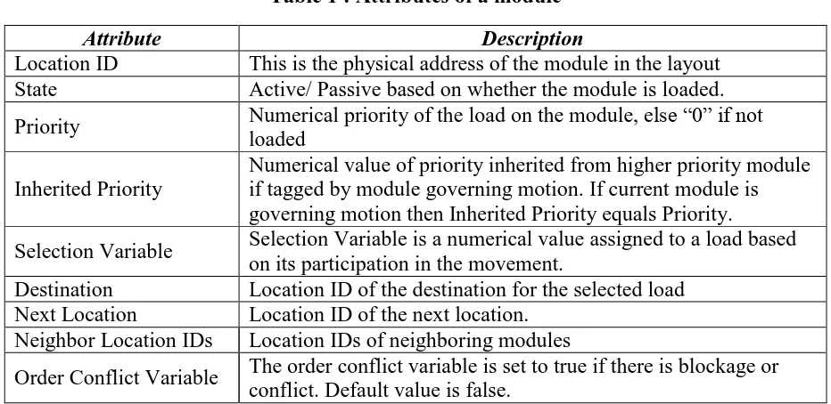
Table 1 provides a description of the attributes of the modules. The load-module pairs change
when movement occurs and every time a new load arrives on a module, the modules need to
update their information
Table 1 : Attributes of a module
Attribute Description
Location ID This is the physical address of the module in the layout
State Active/ Passive based on whether the module is loaded.
Priority Numerical priority of the load on the module, else ―0‖ if not
loaded
Inherited Priority
Numerical value of priority inherited from higher priority module if tagged by module governing motion. If current module is governing motion then Inherited Priority equals Priority.
Selection Variable Selection Variable is a numerical value assigned to a load based on its participation in the movement.
Destination Location ID of the destination for the selected load
Next Location Location ID of the next location.
Neighbor Location IDs Location IDs of neighboring modules
All modules in the system are equipped with the same control logic and each module
functions independently of the other modules in the system. The de-centralized control
system enables the modules to function like autonomous objects in the constrained space of
the layout. The control logic follows a four-step process to execute the algorithm and move
to its destination. Modules that carry loads which intend to move to a destination will be
called ―order loads‖ from here on. The order loads initiate movement of other loads so as to
push them out of the way to vacate the next module, thus enabling the order load to move
one step closer to the destination. The control logic is a four-step process that includes
gathering information from the loads, sharing that information with modules, selecting the
next locations for motion and executing motion. The order loads follow all the four steps of
the control logic whereas the other loads use only a part of the control logic. All the modules
in the layout have the capability of governing motion and communicating with modules
around them. Figure 2 shows the control logic as a series of steps that are followed by the
modules in that order.
IDENTIFY Current state and
properties
RETRIEVE Neighbor Information and Properties
SELECT Next Location for
Movement
EXECUTE Movement COMMUNICATE
With neighbor modules
The first step of the algorithm is the identification process, whereby the module checks if it is
loaded i.e., in an active state. If loaded, then the module retrieves the priority value of the
load placed on it. Some of the other load variables that the module retrieves are the Inherited
Priority, Selection Variable, and the Destination of the load it handles. These data are
required by the module in the next steps of the control algorithm. Each of the modules
functions as an object in an Object-Oriented environment and holds the collected information
as its own attributes. The Current Location is unique for each module and is stored in the
module. The Selection Variable for loads is set in the next steps when modules are tagged
for next location. Figure 3 shows the identification process for modules.
IDENTIFY
CURRENT MODULE LOADED SET STATE = 1
( ACTIVE)
SET STATE = 0 ( PASSIVE)
YES
NO
OBTAIN LOAD VARIABLES
· PRIORITY
· SELECTION VARIABLE
· INHERITED PRIORITY
· DESTINATION
SET DEFAULT
VALUES
· PRIORITY = 0
· SELECTION VARIABLE
· INHERITED PRIORITY = 0
· DESTINATION = 0 SET
CURRENT LOCATION
Figure 3 : Identification process for modules
After identification, if the module is loaded, then it interacts with the neighboring modules
and retrieves information pertaining to their load variables. The information sharing between
stage, the module also determines its neighbors and communicates with all the modules that
are its immediate neighbors. The information from neighboring modules consists of Location
ID, State, Priority, Inherited Priority, and Selection Variable. Following the first two steps,
which are primarily for data collection, the third step is the decision on the next location.
Only the order loads get the choice of next locations and hence this step is used only for the
order loads. For the non-order loads, their next location is decided by any order load that
governs its motion. Once the module gets information from the load it carries, as well as of
the neighboring modules, the control algorithm uses comparison of properties as a way of
narrowing down the list of feasible options between the neighbors. The neighbors are
shortlisted based on the distance from destination, the modules with minimum distance to
destination are chosen. As a rule, this algorithm does not allow any lower-priority module to
tag or select a higher-priority neighbor. The neighbor locations with higher priority than the
current location are rejected. Out of the feasible options, the neighbor with the lowest priority
is chosen as the next location. When no neighbor location is feasible, the load is blocked for
the current time step. This procedure is called the Next Location Search. Figure 4 (A)
illustrates the Next Location Search. Figure 4 (B) shows the naming convention used for
(A) (B)
LOCATION ID INHERITED
PRIORITY
PRIORITY 4
ü
5
Destination
8 9
6
1 2 3
6
9 8
7
4 5
Distance to destination is not minimum Distance to
destination is not minimum
Current Location Priority < Next
Location Priority Minimum Distance
Current Location Priority > Next Location Priority
Figure 4 : Illustration of the next location search
Once a next location is decided, the algorithm checks if the module at the next location is in
active or passive state. If the next location is empty, the load at the current location only has
to move to the next location. The movement process is explained in the subsequent pages. In
the alternative case of the next location being occupied by a load, the algorithm needs to
move the package at the next location out of the current module. The module carrying the
order load initiates an iterative process of tagging lower priority modules amongst its
neighbors until an empty location is found. This is a heuristic approach designed to use the
core principle of this algorithm. The higher-priority loads push the lower-priority loads out of
their way in a bid to get to the destination faster. The tagging process ensures that the order
load passes on its priority to the tagged modules, indicating its hold over the resources until
of orthogonal translations (movements to vacate the module at the next location for the order
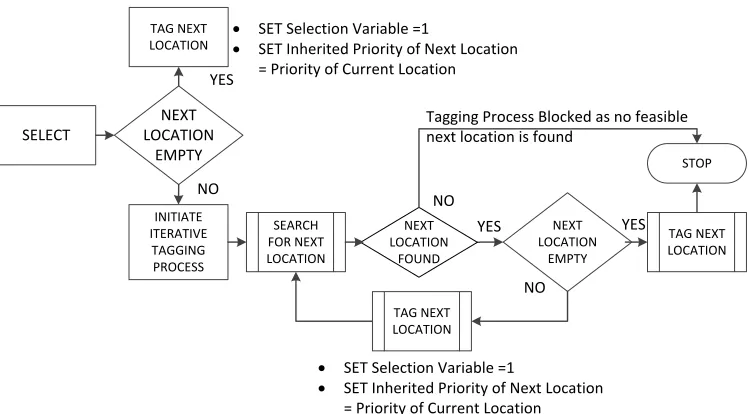
load to move. Figure 5 shows the iterative process of tagging modules.
SELECT
NEXT LOCATION
EMPTY YES
TAG NEXT LOCATION
INITIATE ITERATIVE TAGGING PROCESS
SEARCH FOR NEXT LOCATION
TAG NEXT LOCATION NEXT
LOCATION EMPTY
TAG NEXT LOCATION
STOP
NO
YES
· SET Selection Variable =1
· SET Inherited Priority of Next Location = Priority of Current Location
· SET Selection Variable =1
· SET Inherited Priority of Next Location = Priority of Current Location
NEXT LOCATION
FOUND
Tagging Process Blocked as no feasible next location is found
YES NO
NO
Figure 5 : Tagging modules for movement
The process of tagging modules also involves a search procedure, which is similar to the Next
Location Search. However, the search procedure for tagging the modules does not depend on
the distance to destination and thus provides more neighbors to choose from as the potential
next location to be tagged. The algorithm uses comparison of properties as a way of
narrowing down the list of feasible options to choose between the neighbors. The neighbor
locations with lower priority than the inherited priority of the current location are selected as
potential next locations. The algorithm also checks if the neighbor has already been tagged
by some other module, in which case the Selection Variable of the neighboring module
locations satisfying both of the mentioned conditions are the feasible next locations. Out of
the feasible options, the neighbor with the lowest priority is chosen. The failure to find a next
location results in the load being blocked and all the tagged loads to be reset. The load
remains blocked until such time that the search procedures do not find an empty location in
subsequent time steps. In cases where any of the neighbors shortlisted as feasible next
locations are in a passive state (empty), such neighbors are preferred as the next location.
Once a module is tagged as the next location, then it in turn searches for the next location and
this iterative search procedure stops only when some module encounters an empty module as
its next location. The common property between all the tagged modules is the inherited
priority; all the tagged modules inherit the priority of the order load that initiates this
procedure. Figure 6 details the Tagging Modules for movement process. The values at the
bottom right corner indicate the location IDs; the values in the small squares at the top center
indicate the inherited priorities and the numerical values at the center show the priority
values of each module.
Case I Case II
4 7
5
1
8 9
3 6 Empty Space
1
4
7 8
5 2
9 6 3
8 8
8
4 7
5
1
8 9
3 6 Empty Space
1
4
7 8
5 2
9 6 3
8 8
8 8
8 8 8
Module 2 with a priority level of 4 and an inherited priority level of 8, searches for a
potential next location. Module 3 (Case I) is tagged as next location as the priority of module
3 is lesser than the priority of module 1. Since another load occupies Module 3 having
priority 1, hence Module 3 will start the search for the next location to be tagged and the only
option it has is module 6. The inherited priority of module 3 is ―8‖ which is lesser than the
priority of the module 6 which is ―9‖. In such a case the module tagging process is
interrupted. Since no empty location has been found, the algorithm then backtracks and at
Module 2, chooses the only other available module for motion (Case II). Now module 1 is
chosen as the next location since it satisfies all criteria in the selection process. For Case II, It
can be seen that if module 1 is picked, then a sequence of modules to be tagged can be
generated to find an empty location at the bottom right corner. All modules tagged for case
II satisfy the criteria that the priority of the potential next location need be lesser than the
inherited priority of the module searching for next location.
The last step in the control logic is moving the loads over the modules. The Movement
process begins when the modules tagging process finds an empty location. As described in
Section 3.3, the movement is orthogonal, and the algorithm supports block movement of
loads, i.e., moving the loads on these modules takes more than one time step, as the change
of orientation in movement would result in some loads having to wait and suffer a delay of
one time step before they can move. Figure 7 shows that load at module 4 needs to wait for
one time step, whereas loads at module 1, 2, and 3 can move together in one time step. There
movement process leads to different order loads having to wait for a varying amount of time
before moving to their next location. This delay depends only on the number of modules
tagged for movement and may change in case of a conflict. Conflicts and blockages are
discussed in the next section.
1 2 3
4
Breaking Movement into
time steps
Figure 7 : Movement of loads
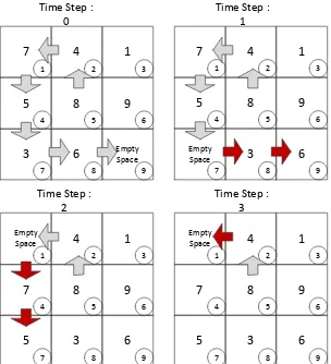
The same procedure is used in the example in Figure 8 where for moving the load at module
5 to module 2, a series of orthogonal translations over 4 time steps is required. All loads
travelling in the same direction move together in one time step and the remaining modules in
the tagged sequence will move in the future time steps depending on the orientation of
movement. Table 2 shows breaking of a movement sequence over four time steps.
Table 2 : Movement of loads over multiple time steps - example
Time Step Tagged Modules Modules participating in movement
t = 1 5, 2, 1, 4, 7, 8, 9 7, 8, 9
t = 2 5, 2, 1, 4, 7 1, 4, 7
t = 3 5, 2, 1 1, 2
Time Step : 0
Time Step : 1
Time Step : 2
Time Step : 3 5 4 8 5 9 6 3 7 6 8 Empty Space 9 7 1 2 4 1 3 7 4 8 5 9 6 5 7 3 8 6 9 Empty Space 1 2 4 1 3 7 4 8 5 9 6 5 7 3 8 6 9 Empty Space 1 2 4 1 3 5 4 8 5 9 6 Empty Space 7 3 8 6 9 7 1 2 4 1 3
Figure 8 : Illustration of load movement
When a load moves from one module to another the properties of the modules change and the
modules constantly need to update the information they carry about the loads and the state
they are in. The real time updating of information is crucial to the process of movement and
also to the search of next locations. The proposed algorithm uses the steps described in this
section to enable movement of multiple loads in a warehouse simultaneously. The movement
resource (module) and these conflicts need to be resolved during run time. The following
section explains the process of moving multiple loads simultaneously to their destinations.
3.5 Simultaneous Movement of Multiple Packages: Conflicts & Blockages
The proposed algorithm can be used for simultaneous movement of multiple loads to
multiple destinations using a list of the order loads called the Order List. The order list is a
list of all Selected Loads in decreasing order of priority. The order list executes the control
algorithm for each load in the list. In each time step all the loads in the order list undergo
some processing as per the control logic. The key advantage that this system provides is the
sequential processing of all loads wanting to move to some destination at every time step. In
addition, at every time step, the load with the highest priority gets to choose modules for
movement to its next location and Order Loads are processed in decreasing order of priority.
The difference between moving a single package and multiple packages is the possibility of
conflicts in the load movement. The proposed algorithm factors in some conflict resolution
that is not too complex in implementation and is in tune with the low level nature of the
algorithm. In order to explain the conflicts and blockages and the built-in resolution methods,
we will assume a layout similar to the one discussed in Section 3.2.
Case I: Two Order Loads trying to access the same module for movement
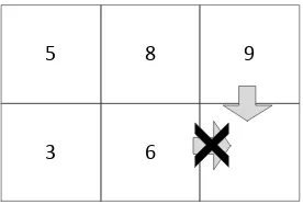
As shown in Figure 9, a conflict arises when more than one order load tries to access the
the first access of modules to the higher priority load and once a particular load has chosen a
set of locations, they become unavailable for other order loads until such time their motion is
complete.
5 8 9
3 6
Figure 9 : Multiple loads accessing the same resource
As is shown by Figure 9, once a module is chosen by an order load as its next location, the
module is blocked for all other loads trying to access it for movement. The next location
module is then available for motion only when movement of load with priority 9 is complete.
Case II: Higher priority order load tags a lower priority order load
The second case for conflicts arises when a higher priority order load tags a lower priority
order load for movement. This creates a problem as both order loads have their own
destinations and trying to move to destination in the fewest possible steps. In a situation
where a higher priority order load say X tags a lower priority order load, say Y, the lower
priority order load Y then behaves like any other normal package and is moved according to
the movement sequence generated by X. It is only after the load Xreleases its hold on Y, that
processing of a lower priority order load when a higher priority order load tags it for
movement. As shown, in the time step 1, the order load 6 does not hold its properties of an
order load and is not processed for its movement closer to its destination. Rather, it behaves
like a normal package to allow the higher priority order load 7 to execute its movement. It is
only in the time step 2 that the Order Load 10 (earlier 6) is processed.
Destination 2
3
Empty Space Time Step : 1
4 Destination 1 5 1 8 9 10 Empty Space 6 1 4 7 2 3
5 6 8
9 10 11 12
ORDER LIST = {7,6 }
DESTINATION FOR ORDER LOAD 1 : 1 DESTINATION FOR ORDER LOAD 2 : 4
TIME STEP : 1
~~~~~~~~~~~~~~~~~~~~~~~~~ PROCESSING FOR LOAD 7 ---NEXT LOCATION : 6
LIST OF LOCATIONS FOR NEXT LOCATION : {7,6,10}
MOVE LOAD 6 -> 10
PROCESSING FOR LOAD 6 ---ORDER LOAD CONFLICT NEXT LOCATION :
-NO MOVEMENT IN THIS TIME STEP
---TIME STEP : 2
~~~~~~~~~~~~~~~~~~~~~~~~~ PROCESSING FOR LOAD 7 ---NEXT LOCATION : 6
LIST OF LOCATIONS FOR NEXT LOCATION : {7,6} MOVE 7 -> 6
PROCESSING FOR LOAD 10 ---NEXT LOCATION : 11
LIST OF LOCATIONS FOR NEXT LOCATION : {10,11,12}
MOVE 11 -> 12 AND 10 -> 11 Time Step : 2
9 9 9 Destination 2 3 Empty Space 4 Destination 1 5 1 Empty Space 9
10 8 6
1 4
7
2 3
5 6 8
9 10 11 12
9 9
8 8
Figure 10 : Higher priority order load tagging a lower priority order load
In such kinds of conflicts, the Next Location for the lower priority load gets reset and the
Order Load 2 is reset when it is tagged for movement by Order Load 1. Once Order Load 2
has executed its movement for Order Load 1, the hold is released and Order Load 2 will have
to reinitiate the search for its next location and subsequently tag other modules for
movement.
Case III: Lower priority Order Load blocked by higher priority load at destination
This conflict occurs specifically in situations when all the destinations are grouped together
and a higher priority order load, say X, gets to destination faster than a lower priority order
load, say Y. The lower priority load gets blocked while trying to get to its destination.
9 Order Load 2
10 Order Load 1
Destination for Order
Load 2
5 8 3
Empty Space
4
1 2 3 4
5 6 7 8
Figure 11 : Lower priority order load blocked while getting to destination
Figure 11 shows the blockage caused due to the Order Load 1 being blocked for movement
to destination 3 because a higher-priority load at location 2 is at destination. The load at 1 is
unable to select module 5 as next location since it is not the module with the minimum
distance to destination. To solve this blockage, the algorithm will assign a temporary
is closer to the original destination of the blocked module but allows the current blockage to
be released. The assignment of the temporary destination is done automatically after the
module checks two conditions and if the two conditions are met then a temporary destination
is assigned to the blocked load.
The following two conditions are checked:
1. All loads higher than the blocked load need to be at their destinations.
2. The temporary destination is not the destination for any other order load.
9 Order Load 2
10 Order Load 1
Destination for Order
Load 2
5 8
Temporary destination for Order
Load 2
Empty Space
4
1 2 3 4
5 6 7 8
Figure 12 : Assignment of a temporary destination to blocked order load
Figure 12 shows the assignment of a temporary destination to the blocked order load. In the
figure, location 7 is assigned as the temporary destination and hence the blocked load at 1
can move towards the temporary destination 7 by choosing location 5 as it next location.
Once Order Load 2 reaches its temporary destination, the algorithm re-sets the original
destination from memory and the Order Load can move towards its original destination
without being blocked. Using the control concept explained in this chapter, the algorithm can
destinations. With the current design of the control system, the possibility of a complete
―lock up‖ of packages is eliminated. The the highest priority package always manages to get
its way to its destination provided there is at least one empty space for facilitating movement.
The following chapter details the control algorithm and presents some of the results of the
CHAPTER 4: Priority-based Control Algorithm
4.1 Introduction
The complete priority-based control algorithm is presented in this chapter, along with an
example of the package movement scenario and a summary of results. As discussed in the
last chapter, the control algorithm can be divided into three main procedures: the main
section that controls the motion of all the order loads, the subsection which helps the order
loads decide on the next location for movement, and the subsection that tags modules
involved in movement of the order load from the current location to the next location.
4.2 The Control Algorithm
The main body of the algorithm is the implementation of the first, second and fourth steps of
the control logic explained in Section 3.4. The steps of identification, communication,
information retrieval and movement all form a part of the main body. The third step of
searching for a next location and subsequently tagging modules for moving the Order Load at
current location to the next location is shown as sub process 1 and sub process 2. Sub process
1 is the procedure for searching for Next Location and sub process 2 details the module
tagging procedure. On the following pages, a step-by-step procedure is explained for the
main body of the algorithm followed by Figure 15 and Figure 16. These are the flow charts
of the two sub processes, Next Location Search and Tagging modules for movement. The
Procedure
Get Order List
While All Order Loads not at destinations
For each Order Load
If Order Load at destination then
Skip Order Load for processing.
End If
If Order Load conflict then
Skip Order Load for processing (Order Load blocked) and Reset tagged loads
End If
If Order Load blocked by higher priority Order Load at destination then
If All Order Loads with higher priority at destinations then
Assign a temporary destination to current Order Load
Else
Skip Order Load for processing (Order Load blocked) and Reset tagged loads
End If
If Order Load at temporary destination then
Reset destination as original destination
End If
If Movement sequence from last time step complete then
Next Location Search, Tag Modules for Movement
Execute Movement as per new sequence.
Else
Execute Movement sequence pending from last time step
End If
End For
Update t = t + 1
End While. Report Retrieval Time t.
End Procedure
The first step is the information gathering process, where the control algorithm retrieves the
location ids of all order loads, and also the priorities of packages in the layout. Order List
processing starts at time t = 0. The algorithm checks if all the Order Loads are at their
destinations. If the check condition returns true, then no further processing is required and the
algorithm returns the retrieval time t. If the check condition returns false, the algorithm
continues with processing the Order List. Only the Order Loads that are not at destinations
will be processed and the processing is a recursive process until such time all Order Loads
are at destinations. For each of the Order Loads, the following check points are put in place
to determine the participation of the Order Load in the current time step. Next step is
checking if there has been an Order Load conflict for the current Order Load. An Order Load
conflict occurs when a lower priority Order Load is tagged by a higher priority Order Load
for movement. In such cases, the lower priority Order Load ceases to behave as an Order
Load and waits till it has moved as per the sequence of the higher priority Order Load, and
then resumes its motion towards its destination. In case of an Order Load conflict, the lower
priority order load is skipped for processing in the Order List and any modules tagged by the
lower priority Order Load in the past time steps are reset. The next check point in the
sequence is to check if any of the lower priority Order Loads is blocked due to a higher
priority Order Load at destination. This kind of a conflict is explained in detail in Section 3.5
as Figure 11. In such cases a temporary destination needs to be assigned to the lower priority
load so that a new route can be negotiated since the lower priority Order Load cannot push a
higher priority Order Load. The algorithm will report a blockage, reset any tagged modules
temporary destination can only be assigned if all the Order Loads having a higher priority as
compared to the blocked load are at their destinations. The temporary destination is set in a
way where it takes the lower priority Order Load around the higher priority Order Load
which is at destination. The next processing step is to check for the Order Load to be present
at its temporary destination in the current time step. If yes, then the original destination for
the Order Load is restored enabling the Order Load to move to its original destination from
the next time step. Once the initial checks are complete, the algorithm needs to check if the
current Order Load has pending movement sequence from the last time step; in such a case
the Order Load has a next location already decided and it will not be considered for the
search process explained until the movement sequence has been executed successfully. Only
when the movement sequence from a past time step is complete or in case of conflicts and
blockages leading to resetting of tagged modules, can the Order Load be considered for the
Next Location Search and Tagging Modules for Movement process.
If the Order Load has completed its movement sequence from the past time steps and is not
blocked then it is allowed to initiate search for the next location and tag modules for
movement. The Order Loads that have been assigned temporary locations and those at
temporary destinations are also considered for this step. The two processes of Next Location
Search and Tagging Modules for Movement are explained in detail in Figure 15 and Figure
16 on the following pages. If any of the two sub processes are unable to find a next location
and report a blockage, then the processing for the current Order Load is skipped for this time
process and now movement is executed as per the procedure explained in the last chapter,
i.e., depending on the movement orientation; the sequence is executed over multiple time
steps. In the movement step, movement sequence pending from the last time step is used or if
a new search was executed successfully in the current time step, then the new movement
sequence is used. Only movement for the current time step is carried out in this step, the
other tagged modules retain their inherited priorities and will move in the future time steps.
The procedure explained above is repeated for all Order Loads eligible for processing within
the Order List. Processing for one time step t is complete. Movement occurs for all Order
Loads simultaneously in each time step. The procedure is repeated until all Order Loads are
at destinations and retrieval time t is reported.
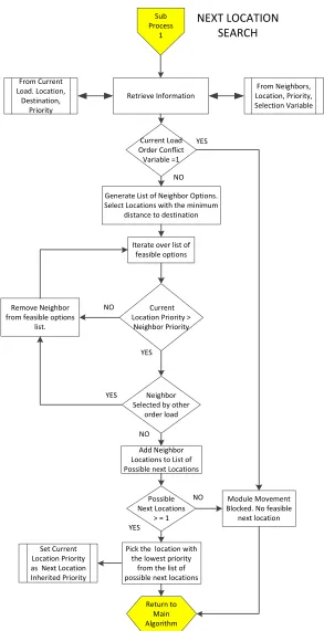
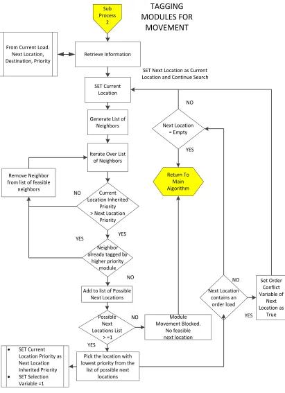
On the following pages the sub processes of Next Location Search and Tagging Modules for
Movement are explained in Figure 15 and Figure 16. Figure 14 shows the Key to the charts.
Custom sub procedure start
Process
Decision Box Sub Process of a
main process
Custom sub procedure end
NEXT LOCATION SEARCH Retrieve Information Sub Process 1 From Current Load. Location, Destination, Priority From Neighbors, Location, Priority, Selection Variable
Generate List of Neighbor Options. Select Locations with the minimum
distance to destination
Iterate over list of feasible options
Current Location Priority >
Neighbor Priority Remove Neighbor
from feasible options list.
NO
Neighbor Selected by other
order load YES
YES
NO
Add Neighbor Locations to List of Possible next Locations
Possible Next Locations
> = 1
Pick the location with the lowest priority
from the list of possible next locations
YES
NO Module Movement Blocked. No feasible
next location Return to Main Algorithm Set Current Location Priority as Next Location Inherited Priority Current Load Order Conflict Variable =1 NO YES
Sub Process
2
Retrieve Information From Current Load.
Next Location, Destination, Priority
Generate List of Neighbors SET Current Location Current Location Inherited Priority > Next Location
Priority Iterate Over List
of Neighbors
Remove Neighbor from list of feasible
neighbors NO NO YES YES Next Location = Empty YES Return To Main Algorithm SET Next Location as Current Location and Continue Search
NO
Add to list of Possible Next Locations
Possible Next Locations List
> =1
Pick the location with lowest priority from the
list of possible next locations
· SET Current Location Priority as Next Location Inherited Priority
· SET Selection Variable =1 YES NO Module Movement Blocked. No feasible next location Next Location contains an order load
NO Set Order
Conflict Variable of Next Location as True YES TAGGING MODULES FOR MOVEMENT Neighbor already tagged by
higher priority module
4.3 Scenario I
To illustrate the working of the algorithm, two scenarios will be considered. The first
scenario is a 6 x 6 configuration with four randomly placed order loads in the layout. The
destinations/ docks for these loads are placed at 4 corners. The chances of a lower priority
load being pushed away from its destination are very high in this kind of a layout, as all the
four order loads move in different directions. Figure 17 illustrates Scenario I.
1 2 3 4 5 6
7 8 9 10 11 12
13 14 15 16 17 18
19 20 21 22 23 24
25 26 27 28 29 30
31 32 33 34 35 36
DESTINATION FOR ORDER LOAD 1
DESTINATION FOR ORDER LOAD 2
DESTINATION FOR ORDER LOAD 3
DESTINATION FOR ORDER LOAD 4
LOCATION ID INHERITED
PRIORITY
PRIORITY
Figure 17 : Scenario I for priority based control algorithm
For the example in Figure 18, a 6 x 6 layout is considered for easier explanation. At t = 0, the
order placement is shown along with the destinations for each of the order loads. There are 4
order loads with priorities 33, 32, 31, 30 placed at locations 24, 15, 33, 12. It is seen that at
time t = 1, the Order Load 4 is blocked for movement. The priority for this load is 30, which
feasible location it can move to, is location 7 which is being used by Order Load 1 with a
higher priority. Hence Order Load 4 remains blocked for the first time step. The Order Load
3 makes a move towards its destination whereas the other two Order Loads initiate
movement of some loads in the time step t = 1. Order List is maintained by Location IDs.
TIME T=1
0
1
13 17 5 12 0
0 9 32 2 15 30
0 0 0 0 27 7
14 0 3 19 10 33
6 0 1 11 18 4
0 31 0 26 29 0
2 3 4 5 6
7 8 9 10 11 12
13 14 15 16 17 18
19 20 21 22 23 24
25 26 27 28 29 30
31 32 33 34 35 36
31 32 33 33 30 33 33
Order List :[24, 15, 33, 12]
---Next Location for Module : 24 is : 18
Modules Tagged for Module: 24 are : [24, 18, 17, 16, 10] Movement in Current Iteration: [16, 10]
Movement in Next Iterations: [24, 18, 17, 16]
---Next Location for Module : 15 is : 9
Modules Tagged for Module: 15 is : [15, 9, 3] Movement in Current Iteration: [15, 9, 3]
---Next Location for Module : 33 is : 32 Modules Tagged for Module: 33 is : [33, 32] Movement in Current Iteration: [33, 32]
---Next Location for Module : 12 is : No Module Movement for Module : 12
0
1
13 0 5 12 0
0 9 17 0 15 30
0 0 32 2 27 7
14 0 3 19 10 33
6 0 1 11 18 4
0 0 31 26 29 0
2 3 4 5 6
7 8 9 10 11 12
13 14 15 16 17 18
19 20 21 22 23 24
25 26 27 28 29 30
31 32 33 34 35 36
32
31
30
33
TIME T=0
Order List :[24, 15, 33, 12]
---Destination for Order Load with Priority 33 At Location : 24 is Location 1
Destination for Order Load with Priority 32 At Location : 15 is Location 6
Destination for Order Load with Priority 31 At Location : 33 is Location 31
Destination for Order Load with Priority 30 At Location : 24 is Location 36