ABSTRACT
ROGERS, TATE WESTON. Modification of Power Earth Augers for Pit Latrine Extraction in Developing Countries. (Under the direction of Robert C. Borden).
There are hundreds of thousands of pit latrines in the developing world that require regular emptying to control disease and reduce childhood mortality. Unfortunately, many of these pits are in difficult to access locations (down narrow alleys, inside buildings, hillsides, etc.) and cannot be accessed using currently available equipment (e.g. large vacuum trucks). As a result, many pits are emptied manually exposing the workers and surrounding
communities to a broad array of fecal borne pathogens.
Modification of Power Earth Augers for Pit Latrine Extraction in Developing Countries
by
Tate Weston Rogers
A thesis submitted to the Graduate Faculty of North Carolina State University
in partial fulfillment of the requirements for the degree of
Master of Science
Environmental Engineering
Raleigh, North Carolina 2013
APPROVED BY:
_______________________________ ______________________________
Robert C. Borden Tarek N. Aziz
DEDICATION
BIOGRAPHY
ACKNOWLEDGMENTS
I would first like to thank all of my friends, fellow students, and professors for the great and challenging experience on the pursuit of my Bachelor’s and Master’s degrees here at NC State. I am very grateful for my advisor, Dr. Borden, for his professional guidance, support, and patience. I would also like to thank my other committee members, Dr. Aziz and Dr. de los Reyes, for their continued support throughout this interesting project.
I would like to thank Stewart Farling, Andrew Young, David Black, and Walt Beckwith for their time, help, and friendship throughout the process. I am also grateful to Curtis Powell and the NC State Dairy Farm for their time and support. A special thanks to Jake Rhoads for his endless help with fabricating any necessary materials.
TABLE OF CONTENTS
LIST OF TABLES ... vii
LIST OF FIGURES ... viii
CHAPTER 1 ... 1
1. INTRODUCTION ... 1
1.1 Global Sanitation Crisis ... 1
1.2 Extraction Auger Concept... 4
CHAPTER 2 ... 8
2. PROPOSED EXTRACTION AUGER DESIGN ... 8
CHAPTER 3 ... 15
3. METHODS ... 15
3.1 Laboratory Testing ... 15
3.1.1 Simulant Waste ... 15
3.1.2 Setup ... 16
3.2 Field-testing ... 17
3.2.1 Rogers Farm ... 18
3.2.2 NC State Dairy Farm ... 18
CHAPTER 4 ... 19
4. EXTRACTION AUGER OUTCOMES ... 19
4.1 Hydraulic Performance ... 19
4.1.1 Flow Output ... 19
4.1.2 Jamming ... 20
4.2 Usability of Extraction Auger ... 21
4.2.1 Maneuverability ... 21
4.2.2 Cleaning ... 21
4.2.3 Deterioration of Extraction Auger Components ... 22
4.2.4 Modularity... 23
CHAPTER 5 ... 24
5. LABORATORY TESTING WITH SIMULANT WASTE ... 24
5.1 Laboratory Testing ... 24
5.1.1 Results from Laboratory Testing ... 24
CHAPTER 6 ... 30
6. FIELD-TESTING ... 30
6.1 Initial Field-testing of Mechanical Drive Auger ... 30
CHAPTER 7 ... 34
7. CONCLUSIONS AND RECOMMENDATIONS ... 35
CHAPTER 8 ... 37
8. REFERENCES ... 37
APPENDICES ... 40
APPENDIX A – The Global Sanitation Crisis, the Development of Pit Latrine, and the Development of Pit Latrine Emptying Technologies ... 41
A.1 Introduction ... 41
A.2 The Pit Latrine ... 43
A.3 Pit Emptying Complications ... 45
A.4 The Need for New Pit Latrine Emptying Technologies ... 52
A.5 Current Pit Latrine Emptying Technologies ... 52
A.5.1 Pit Screw Auger ... 57
APPENDIX B – Laboratory Testing ... 61
B.1 Formulation of Simulant Waste ... 61
B.2 Initial Design Process of Extraction Auger ... 66
APPENDIX C – Field-testing ... 77
C.1 One man 43 cc 2 HP Mechanical Drive Engine ... 77
C.1.1 Description ... 77
C.1.2 Rogers Farm Testing ... 78
C.1.3 Dairy Farm Testing ... 80
C.2 Hydraulic Drive Motor with Gasoline Engine ... 83
C.2.1 Engine and Hydraulic Motor ... 83
C.2.2 Dairy Farm Testing ... 83
C.3 Two man 160 cc 5.5 HP Mechanical Drive Engine ... 90
C.3.1 Engine Description ... 90
C.3.2 Dairy Farm Testing ... 90
LIST OF TABLES
Table 6.1 Average flow rates for the exposed 6-inch choke and with a half-trough design
for a constant and variable lift height. ... 32
Table 6.2 Extraction Auger performance on dairy waste for 1/32-inch and 1/8-inch clearances with a 6-inch exposed choke. ... 33
Table A.1 Human waste characteristics for various countries ... 48
Table A.2 Characteristics of Current Pit Latrine Technologies ... 55
LIST OF FIGURES
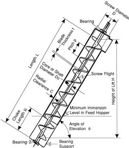
Figure 1.1 Final Extraction Auger design. ... 4 Figure 1.2 Basic screw conveyor variables ... .6 Figure 2.1 Schematic of steel coupling for connecting pipe sections ...10 Figure 2.2 Section of double helix reverse flights connected to the HDPE single flight
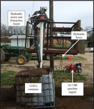
auger before the addition of the pipe casing. ... 11 Figure 2.3 Hydraulic motor version of Extraction Auger recycling dairy waste from a
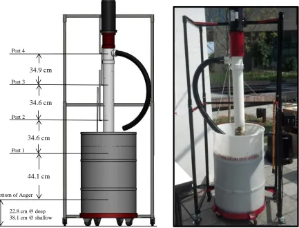
1230 L container. ...14 Figure 3.1 Experimental setup of Extraction Auger ...16 Figure 5.1 Flow rate vs. auger rotational speed with a 5.1 cm (2 in) choke length for
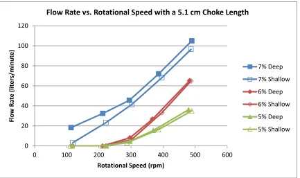
shallow (120 cm lift height) and deep (105 cm lift height) settings for three different bentonite mixtures. ...25 Figure 5.2 Flow rate vs. auger rotational speed for 5.1 cm (2 in ) and 10.2 cm (4 in) choke
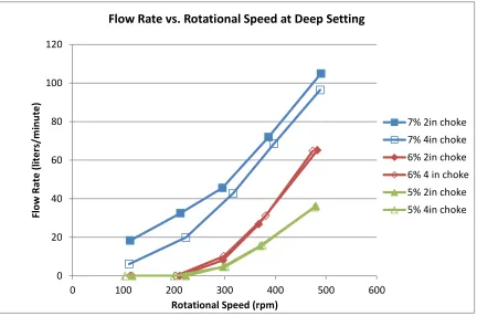
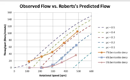
lengths in the deep setting (105 cm lift height) for three different bentonite mixtures. ...26 Figure 5.3 Observed flow rates for a 5.1 cm (2 in) choke length and deep setting (105 cm
lift height). Theoretical flow rates are based on Roberts (2001) derivation for flow through a screw conveyor for varying material friction coefficients
(μc)….. ...28 Figure 6.1 Field-testing the Extraction Auger at the Rogers farm with the 43cc 2 HP
Figure 6.2 Dairy waste being recycled into the 1 m3 container with the Hyrdraulic drive
version of the Extraction Auger with a 2.7 m auger length. ... 34
Figure A.1 Proportion of the population using improved sanitation in 2010. ...42
Figure A.2 An example of an improved sanitation facility, the Ventilated Improved Pit latrine and of an unimproved sanitation facility, a hanging latrine ... 43
Figure A.3 Manual pit latrine emptying or "scavenging" in Dar es Salaam, Tanzania ...45
Figure A.4 Densely populated community that presents a difficult task for large pit emptying equipment to gain access. ... 46
Figure A.5 Pit latrine that must be accessed from the side because of a design not compatible with pit emptying ... 47
Figure A.6 A “dry” pit latrine and a “wet” latrine found less than one mile apart. ...50
Figure A.7 Pit latrine with high solid waste content near Durban, South Africa ... 51
Figure A.8 Current pit latrine technologies ...56
Figure A.9 Pit Screw Auger being tested in a pit latrine. ... 57
Figure A.10 Pros and cons of the Pit Screw Auger design.. ... 59
Figure B.1 Viscosity versus shear rate profiles for the high yield bentonite mixtures used for simulant waste. ...61
Figure B.2 7% bentonite clay mixture in a 210 L drum ... 66
Figure B.3 Initial prototype of the Extraction Auger ...68
Figure B.4 Initial Extraction Auger schematic ...70
Figure B.6 Schematic of the inlet of the Extraction Auger with the metal double helix bit.. ... 73 Figure B.7 The head produced at the outlet (port 4) for varying bentonite concentrations at the deep setting (105 cm lift height) and with a 5.1 cm choke length... ... 75 Figure B.8 Head produced at each port for the 7% bentonite mixture, deep setting (105 cm lift height), and 10.2 cm choke length.. ... 76 Figure B.9 Flow rates produced for single versus double helix metal inlet tips at the deep
setting (105 cm lift height) with a 10.2 cm choke length... ... 76 Figure C.1 10% bentonite mixture being mixed in the simulated pit. ...78 Figure C.2 7% bentonite mixture with the addition of horse manure ... 79 Figure C.3 The Extraction Auger prototype with the 43cc engine recycling dairy waste
from the settling basin after the addition of the section of reverse flights ...81 Figure C.4 Schematic of the reverse flights within the wye fitting and the metal double
helix reverse flighted section before pipe is attached. ... 82 Figure C.5 Hydraulic unit mounting front at multiple views. ...84 Figure C.6 Dairy farm setup to simulate emptying from a 1.6 m deep pit. ... 85 Figure C.7 Deterioration of a section of pipe after testing with the hydraulic motor in dairy waste. ...88 Figure C.8 The inlet of the auger after a piece was snapped off when using the hydraulic
CHAPTER 1
1. INTRODUCTION
1.1 Global Sanitation Crisis
The lack of proper sanitation in the developing world causes an estimated 2.5 billion yearly cases of diarrhea, resulting in the death of over 1.5 million children (WHO and UNICEF 2009). The Millennium Development Goal set in 1990 of halving the global population without access to proper sanitation is projected to fall well short, leaving an estimated 2.6 billion still without as of 2010 (UN 2010).
Pit latrines provide improved sanitation at a relatively low cost. Ventilated improved pit latrines (VIP) and pit latrines with a slab that ensure the hygienic separation of humans from their excreta are considered an improved sanitation source by the World Health
Organization (WHO and UNICEF 2008). Pit latrines can have various superstructures and pit designs. Pit volumes vary between 1 and 4-m3 with typical depths of up to 2 m (Still 2002; Mara 1984). The accumulation rates in these pits vary tremendously within the same area and between areas with fill times ranging from 3 to 20 years (Still 2002). The fill rate is
variable between pits and within a specific pit. Every pit latrine has specific characteristics; however, most pits form three layers from top to bottom: floating scum, liquid, and sludge layers. If the pit is “dry” or well drained, then it is typical for only a sludge layer to be present. The consolidated sludge layer is reported to have densities up to 1,750 kg/m3 and behaves more like a soil as it does not readily flow (Hawkins 1982)(Radford 2011). “Dry” pit latrines generally show a trend of decreasing moisture content from the surface of the pit to a 1 m depth and little to no change past that depth (Still and Foxon 2012a).
Pit emptying is a necessary service for the hundered of thosands of pits that are filling annually in the developing world. However, pit emptying is a difficult process for the users and laborers. Typical sewage removal technologies, such as large vacuum tankers, are often prohibitively expensive or incapable of reaching the pits in dense urban slums and difficult rural terrain. In some cases, the pit contents are only accessible through the toilet hole within the superstructure or by drilling holes in the side of the latrine (Still 2002). Up to 20% of the pit contents may be solid waste (trash) in some countries (Still 2002). Large amounts of trash can cause severe operational problems in with many mechanical pit emptying devices. The lack of user capital and access to a proper emptying technology often results in manual excavation of the pit waste. Manual excavation often exposes the laborers and users to pathogens contained within the pit contents including: Ascaris, Giardia, Trichuris,
Cryptosporidium, and Taenia. These pathogens survive for long periods and transmit through
new pit emptying technologies to provide an effective, affordable, and sanitary option for the pit emptying labor force.
Several organizations are developing new mechanisms in an attempt to provide effective and sanitary pit emptying. These technologies fall into three categories: manual, semi-mechanized, and fully mechanized (O’Riordan 2009). Manual pit emptying ranges from only a bucket to elongated shovels and tools used from outside the pit. Most of the existing semi-mechanized technologies are manually powered mechanisms to pump or lift the waste out of the pit. The fully mechanized equipment involves primarily smaller and more
maneuverable vacuum pumps compared to the large vacuum trucks. Vacuum tankers are often limited to typical empty depths of only 0.8 m below the ground surface by the available suction power and have difficulty with the dense bottom sludge due to air entering the hose (Still and Foxon 2012a). Excluding the manual pit emptying methods, most of the new technologies have proven effective at removing the liquid and scum layers but have difficulty with the dense sludge layer (Thye et al. 2011; Still and O’Riordan 2012; O’Riordan 2009).
The objective for this research was to develop a mechanism to meet as many of the following criteria for an effective pit emptying technology as possible:
- Portable - easily able to access most any pit latrine location - Sanitary – provides hygienic protection of the operator - Effective – quickly removes a wide range of waste
-1.2 Extraction Auger Concept
The Extraction Auger was developed to provide a user friendly and effective method for pit emptying in the developing world. The basic design models the common screw conveyor or screw pump used in the food processing and wastewater industries. As shown in Figure 1.1, the design consists of a gasoline engine powered hydraulic motor that rotates a screw within a pipe that is fastened to the engine mounting. The bottom of the pipe sits at the bottom of the pit and when rotated it would lift the waste up through the pipe and out through a tee fitting. A fabricated attachment piece holds the pipe rigid, attaches it to the engine mounting, and forces the waste out of the pipe through the wye fitting.
Roberts (1964, 1999, 2001) described the mechanics of enclosed screw conveyors for moving bulk materials and developed Equation 1.1 to estimate flow through screw conveyor based on the geometry and the rotational speed of the screw. Vortex efficiency (ηVR) is the
most important parameter in determining flow in Roberts’ model. ηVR must be positive to
generate flow.
(1.1)
Where,
[( ) ( ) ] [ ] (1.2)
(1.3)
Qt maximum theoretical throughput
ηv volumetric efficiency
ηVR rotational or vortex efficiency
ηF fullness efficiency
hav average height of material on the screw surface
p screw pitch (m) D screw diameter (m) Di shaft diameter (m)
ω angular velocity of screw (rev/s) C radial clearance (m)
3-Dimensional modeling of small particles through screw conveyors at different inclinations have shown the rate of material passed through the screw conveyor decreases with an increase in inclination (Owen and Cleary 2009). Screw pumps used for lifting wastewater are typically set at an inclination between 22 and 40 degrees (Lakeside 2004). This implies that the operation of the Extraction Auger should be with as little inclination as possible, although a vertical orientation will be most common in the field.
Demonstrate that the Extraction Auger can lift simulated waste vertically using a typical gasoline powered motor.
Identify critical variables to improve performance.
CHAPTER 2
2. PROPOSED EXTRACTION AUGER DESIGN
The following performance criteria for the proposed Extraction Auger were
developed from reviews of published literature, discussions with field practitioners, and our own laboratory and field tests:
a) Sanitary – To achieve the overall objectives of improving sanitation in developing countries, the Extraction Auger must improve separation of the operator from the waste. This includes equipment set up, transferring the waste from the pit into the transport containers, transport of the waste to suitable disposal location, equipment cleanup, and removal from the site.
b) Portable – Pit latrines are often located in very difficult to access locations such as dense slums or steep terrain with little to no road access. Therefore, a pit emptying mechanism should be able to fit down narrow alleys and operate in tight working areas. The
transportation and operation of the mechanism should require a maximum of two laborers meaning that the total weight of the mechanism should not exceed 50 kg.
remove a wide range of waste viscosities and densities including liquid at the top of the pit and dense bottom sludge. If possible, the Extraction Auger should be able to handle trash within the pit by either 1) passing it through the mechanism with the waste or 2) rejecting large solids from entering the mechanism. At a minimum, the Extraction Auger should allow easy removal of trash that does enter the auger.
d) Maneuverability – In addition to the mechanism being portable, it should also be easy for the operator to maneuver within the pit. One operator should be able to run the
mechanism after it has been placed in the pit while another directs the waste into an appropriate transport container. A mechanism weighing less than 25 kg would provide easy maneuverability and reduced strain on the operator.
e) Durability and Simplicity – A pit emptying mechanism should be robust enough to handle the day-to-day wear experienced in the field. It should also be easy to repair and replace parts in a developing region with limited resources. Simple to understand and operate designs are optimal for easy comprehension of the mechanism by the labor force. f) Modularity – Many pit latrines do not have access to the pit outside of the superstructure.
Rigid mechanisms will be required to be almost 3 m in length to empty a typical pit. Therefore, rigid mechanisms should be capable of assembly within a superstructure while still eliminating contact between the human and the pit contents.
The most effective version of the Extraction Auger consists of a 4-inch (10.2 cm) extraction screw enclosed in a pipe. Waste sludge is transported up the pipe by the rotating action of the screw and then discharges to a collection container through a downward oriented 45-degree wye fitting. A hydraulic motor powered by a remotely located gasoline engine rotates the screw.
The main body of the Extraction Auger consists of a 4-ft (1.2 m) long straight section of high-density 4-inch (shaved down to 3.75-inch (9.5 cm)) high-density polyethylene (HDPE) auger flights mounted on a 1-inch (2.5 cm) stainless steel hex center shaft (Lundell Plastics Corp., Odebolt, IA). The HDPE flights are enclosed in 4-inch (10.2 cm) schedule 40 polyvinyl chloride (PVC) pipe. The top end of the PVC pipe is glued to a 4-inch x 4-inch x 4-inch (10.2 cm x 10.2 cm x 10.2 cm) PVC wye fitting. Waste moves upward through the auger to the wye, turns 270 degrees, and discharges out the wye through a collapsible 4-inch
PVC hose. A handle attached to the discharge end of the collapsible hose to assists in directing the waste into a suitable collection container.
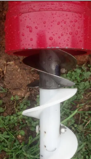
At the bottom (intake end) of the auger, two flights (8-inch or 20.3 cm) of steel auger extend past the end of the PVC pipe to convey waste into the solid pipe portion of the auger. Steel replaces the HDPE in this section to improve the durability of the exposed flights. A 1-inch (2.5 cm) steel ball is welded on a 1 ½-1-inch shaft that protrudes from the bottom of the steel flights to prevent the auger from damaging the bottom of the pit, if it is lined. The length of the Extraction Auger is easily increased to empty deeper pits by attaching additional lengths of HDPE auger and PVC pipe. The HDPE auger comes in 12-inch (30
cm) lengths. The PVC pipe can be connected with 8-inch (20.3 cm) long steel couplings as shown in Figure 2.1.
Inside the wye at the top of the screw, there is an 8-inch (20.3 cm) long section of double helix reverse flights to aid in discharging the solids through the wye into a collection container. In the current version, the reverse flights are manufactured from 1/16-inch (1.6
mm) thick steel plate welded to a 1 ½-inch outer diameter (3.8 cm) (1 ¼-inch inner diameter) steel tubing that slides over an exposed section of hex shaft above forward HDPE flights (Figure 2.2). The steel tubing is mounted to the hex shaft with one 5/16-inch bolt. In future
versions, the reversed steel flights could be replaced with a lighter weight material (i.e. HDPE) if available.
The auger and wye fitting are connected to the hydraulic motor using a specially fabricated coupling machined from a 6-inch diameter nylon piece. The top 2 inches of the PVC wye fitting slides into the coupling to provide a secure fit and is held in place by four
3
/8-inch bolts that are screwed through the fabricated attachment piece into small indentations
in the wye fitting. A fabricated steel shaft passes through the fabricated coupling, connecting the output shaft of the hydraulic motor to the auger. This shaft steps down to 7/8-inch after the
connection to the hydraulic unit so the 1-inch steel hex shaft of the auger was able to slide over and fit tightly. This fabricated shaft protruded 6 inches below the fabricated attachment piece, as shown in Figure 1.1, so that the auger could be fastened to the shaft using two 5/16
-inch bolts.
is rated for the following maximum continuous conditions: speed of 493 rpm, flow of 37.9 lpm (10 gpm), and torque of 148 Nm (1308 lbs.-in) at a maximum pressure of 138 bar (2000 psi). Hydraulic power to drive the motor is supplied by a 10.7 HP (at 3600 rpm) Honda GX340 gasoline engine (Little Beaver Inc., Livingston, TX). Hydraulic fluid is transferred from the hydraulic pump to the hydraulic motor through 7.6 m (25-foot) lengths of hydraulic hoses with Quick-connect fittings. The hydraulic motor, forward and reverse controls, pressure gage and Extraction Auger are mounted to a frame handle bar constructed from 3/4
-inch (1.9 cm) steel pipe (Figure 1.1).
1230 L container
10.7 HP gasoline engine
Hydraulic hoses Hydraulic
motor and Extraction Auger
setup
CHAPTER 3
3. METHODS
This research evaluated the performance of the Extraction Auger in both the laboratory and the field. Construction of the initial prototypes took place mostly in the lab with some fabrication completed through a local machine shop.
3.1 Laboratory Testing
3.1.1 Simulant Waste
A high yield bentonite clay and water mixture was used as a simulant for human waste during the laboratory-testing phase.
Data provided by Stuart Woolley et al. (personal communications, August 2012) indicates that the viscosity of fresh feces varies between 2,200 and 70 Pascal-seconds (Pa-s) for shear rates of 0.2 and 21 1/second (1/s). Preliminary testing in the laboratory at NCSU (see Appendix B) showed that mixtures of bentonite clay and water have similar thixotropic properties with effective viscosity varying from 700 to 0.3 Pa-s for the same range of shear rates. Important advantages of bentonite mixtures over actual feces include: (a) the
wide range of viscosities with the higher percentage bentonite mixtures yielding higher viscosities.
3.1.2 Setup
All laboratory tests were completed with the Extraction Auger using the experimental setup shown in Figure 3.1. All tests were run with the auger oriented vertically for two reasons: (1) flow rate usually decreases dramatically with increases in inclination of the
Port 3
Port 2
Port 1 Port 4
22.8 cm @ deep 38.1 cm @ shallow Bottom of Auger
34.6 cm
34.6 cm 34.9 cm
44.1 cm
auger; and (2) operation the Extraction Auger will be at very steep inclinations in the field (Roberts 1964; Dixon Jr. and Humphries 1995).
Several iterations of the initial prototype design were tested using a 43cc 2 HP engine as the power source until adequate flows were produced. Once a feasible design was
developed, a 1 HP electric motor was used in subsequent laboratory tests. A rheostat was used to control the rotational speed of the auger allowing testing at different speeds. The motor attached to a metal stand that held the prototype vertical and allowed for different height settings. In all of the laboratory tests, a 5-ft (1.52 m) long auger was used with a 4-inch x 4-4-inch x 2-4-inch tee fitting outlet. Clear manometer tubes where attached to the sites of the auger at four locations to examine the change in head produced over the length of the auger. A laser tachometer was used to measure the rotational speed of motor shaft that was marked with a piece of reflective tape. Auger discharge rate was measured in duplicate and averaged by monitoring the time required to fill a 19 L (5-gallon) pail. The laboratory experiments examined the variation in flow rate and discharge pressure with motor speed, auger choke length (auger exposed at pipe bottom), lift height (height from the material level to the outlet), and bentonite solids content.
3.2 Field-testing
3.2.1 Rogers Farm
An Extraction Auger powered by a 43cc 2 HP gasoline engine with a 2.44 m (8 feet) auger was tested with three different materials: 7% bentonite-water, 10% bentonite-water, and 7% bentonite-water with the addition of horse manure. A simulated pit was constructed by burying a 1.52 m (5 feet) long by 46 cm (18 in) diameter section of PVC pipe vertically in the ground and filling with simulated waste. Once filled with waste, the auger was inserted into the larger PVC pipe and used to lift waste out of the simulated pit and into a container to measure discharge rate.
3.2.2 NC State Dairy Farm
Three different versions of the Extraction Auger were tested at the North Carolina State University Dairy Farm waste settling basin. The material used for testing consisted of cow manure and a small amount of sand or wood shavings submerged in a settling basin. This material had a moisture content of 80.9%, and organic content of 9.7%, and an
CHAPTER 4
4. EXTRACTION AUGER OUTCOMES
Several complications and resolutions emerged through the development of the Extraction Auger. The two main areas of focus for the optimization of the Extraction Auger were hydraulic performance and usability.
4.1 Hydraulic Performance
4.1.1 Flow Output
Several parameters influence the flow rate produced by the Extraction Auger including the auger rotational speed, viscosity of the waste, and removal of the waste from the pipe at the outlet. Initial laboratory testing with simulated waste showed that the auger operating at reasonable speeds (100 – 500 rpm) does not generate significant pressure and that continuous flights from inlet to the outlet are needed to produce flow. The rotational speed and viscosity of the material had the greatest effect on the flow produced. A threshold rotational speed of approximately 350 rpm is necessary to attain flow rates greater than 15 lpm during lab testing with the 5% bentonite mixture. The threshold speed decreases to approximately 225 rpm to obtain flows greater than 15 lpm with the more viscous 7% bentonite mixture (discussed in Chapter 5).
389cc 10.7 HP gasoline engine that powers the hydraulic unit has shown to provide enough power during field-testing.
Field-testing indicated that material with high solids content that did not readily flow would become compacted at the top of the auger and not flow out of the 4-inch x 4-inch x 2-inch sanitary tee fitting. Attaching a short section (8 2-inches) of reverse flights at the top of the auger above the outlet prevented waste from jamming at the top of the pipe (Figure 2.2). A 4-inch wye fitting angled downward for the outlet fitting appeared to help the material be removed from the pipe by gravity instead of being forced through a 2-inch fitting.
4.1.2 Jamming
During lab and field-testing, the auger would often jam (stop rotating within the pipe) causing flow to stop. This was assumed to be due to two possible problems: 1) the auger wobbling within the pipe causing the system to bind and 2) material wedging between the edge of the auger flights and the pipe. Two modifications were made to the auger to reduce binding: 1) the coupling between the drive head and the screw auger was modified to provide a more rigid connection (Figure 1.1); and 2) the gap between the HDPE auger flights and the PVC pipe was increased from 1/32-inch to 1/8-inch, by shaving down the HDPE auger. These
two modifications greatly reduced friction and associated binding.
In all cases, a 1-2 second reversal of the auger was effective in dislodging trapped material. This allowed continued pumping of the waste without any other action.
4.2 Usability of Extraction Auger
4.2.1 Maneuverability
For efficient operation, the auger should be easily transported and used by two men. A 4-inch pipe and auger were selected to provide adequate flow while still being
maneuverable with one or two operators. Wrap-around handle bars were fabricated (Figure 2.1) for the operator to easily move the system around within the pit. The use of a hydraulic unit decreased the weight of the Extraction Auger since the gasoline engine powered unit is separate from the hydraulic motor and operators do not have to lift the gas engine. The total weight of the hydraulic unit with an 8.8-ft (2.7 m) auger length is approximately 48 kg (106 lbs.). However, the operator does not have to hold this weight once the auger is resting on the pit bottom or semi-solid material in the pit. An adjustable stand was also developed to help support the auger. The gasoline power hydraulic pump can be located a short distance away from the pit when access is restricted using hydraulic hoses to carry fluid between the hydraulic pump and Extraction Auger. The gasoline powered hydraulic pump is mounted on wheels for easy transport.
4.2.2 Cleaning
reducing the equipment weight and waste spillage outside the pit. If water is available, pouring a steady stream of water through the outlet while running the mechanism in reverse is effective in removing most waste before disassembly. We suggest capping the inlet and outlet of the Extraction Auger between pits to minimize the frequency of cleaning the interior of the system and exposing the operators to the waste. A rubber squeegee with a long handle allows the operator to wipe down the outside of the pipe during emptying. Further work is necessary to develop a good system that prevents contact between the waste and the operator.
4.2.3 Deterioration of Extraction Auger Components
4.2.4 Modularity
CHAPTER 5
5. LABORATORY TESTING WITH SIMULANT WASTE
5.1 Laboratory Testing
The Extraction Auger was tested in the laboratory in a vertical orientation since this is most common in the field. The simulated waste used in the laboratory was prepared with 5, 6 and 7% bentonite to represent a range of viscosities similar to human feces mixed with varying amounts of water. In the laboratory, the Extraction Auger lifted the simulant waste from 210 L (55-gallon) drums and recycled it through a 2-inch (5.1 cm) hose back into the drums.
An electric motor a variable speed control was used to examine the effect of auger rotational speed (100, 200, 300, 400 and 500 rpm) on the flow rate and pressure head produced. Additional variables examined included two choke lengths (5.1 cm (2-inch) and 10.2 cm (4-inch)) and two lift heights (105 cm and 120 cm) at steady state. The study of only two lift heights and the small change in lift height for laboratory testing was a result of spatial constraints within the lab testing facility. A lift height of 105 cm corresponds with a deeper submergence of the pipe and auger into the material, implying a higher amount of head above the inlet of the pipe. Similarly, longer lift heights infer a shallower submergence and a smaller amount of head above the inlet of the pipe.
5.1.1 Results from Laboratory Testing
contents and two lift heights. Sludge lift height was increased by raising the auger up 15 cm, which also reduced the intake submergence by 15 cm. The auger rotational speed and waste viscosity had a great effect on the flow produced. The Extraction Auger was capable of lifting 40 lpm of the 7% bentonite mixture at 300 rpm, allowing a typical pit to be emptied in less than 1 hour. However, a speed of over 500 rpm is required to achieve the same flow rate for a less viscous, more ‘water-like’ 5% bentonite mixture. Changes in lift height had
minimal impact on flow rates for the 5% and 6% bentonite mixtures when auger speed is constant, suggesting that drainage of the fluid back down through the auger for these
mixtures was not a major issue. For the 7% bentonite mixture, the lower lift height / deeper
Figure 5.1 Flow rate vs. auger rotational speed with a 5.1 cm (2-inch) choke length for shallow (120 cm lift height) and deep (105 cm lift height) settings for three different mixtures (5, 6, and 7% bentonite).
0 20 40 60 80 100 120
0 100 200 300 400 500 600
Fl o w R ate ( lite rs/m in u te )
Rotational Speed (rpm)
Flow Rate vs. Rotational Speed with a 5.1 cm Choke Length
intake submergence did produce some increase in flow rate at lower rpm. This most likely occurred because a larger hydraulic head is required to transport the more viscous material into the auger intake because it does not flow as freely as the lower viscosity mixtures. This could limit pumping rates as the pit is emptied, especially for high viscosity waste.
Figure 5.2 shows the effect of choke length (length of exposed auger below the solid pipe) on flow rates over a range of rotational speeds. Choke length also had minimal impact on flow rate for the lower viscosity materials, but did have some impact on flow rate for the highest viscosity material. Again, this is consistent with the idea that the pumping rate of
0 20 40 60 80 100 120
0 100 200 300 400 500 600
Fl o w R ate ( lite rs/m in u te )
Rotational Speed (rpm)
Flow Rate vs. Rotational Speed at Deep Setting
7% 2in choke 7% 4in choke 6% 2in choke 6% 4 in choke 5% 2in choke 5% 4in choke
high viscosity materials may be limited by the rate the material enters the auger intake. Field-testing of a similar screw conveyor in South Africa found the flow rate to decrease by 80% as the pit neared empty (Still and O’Riordan 2012). The large decline in flow in the South African tests may have been due to the higher viscosity of the pig waste used in that study. The small change in flow rate with the 7% bentonite mixture for the different choke lengths may be attributed to the decrease in submergence at the pipe inlet from the removal of 5.1 cm (2-inch) of pipe.
For each bentonite mixture, there was a threshold rotational speed required to produce any flow. Above this threshold, flow increased substantially with increases in rotational speed. Roberts (2001) derivation of flow through a screw conveyor based on fill and vortex efficiencies (Equations 1.1 – 1.3) explains this threshold. Figure 5.3 shows the observed flow compared to the expected flow based on measured and typical values for varying friction coefficients. The friction coefficient, μc, refers to the friction between the material moving
Figure 5.3 Observed flow rates for a 5.1 cm (2 in) choke length and deep setting (105 cm lift height). Theoretical flow rates are plotted based on Roberts (2001) derivation for flow
through a screw conveyor for varying material friction coefficients (μc).
flow of bentonite through a screw conveyor. Instead, it is intended to explain the threshold rotational speed requirements and the increase in throughput due to increases in material viscosity and auger rotational speed. The volumetric efficiency achieved a maximum of approximately 26% at the highest rotational speeds and bentonite concentrations. This low efficiency in these tests is most likely due to the vertical orientation of the auger, which increases in the slip of material backwards through the auger (Roberts 1964).
CHAPTER 6
6. FIELD-TESTING
6.1 Initial Field-testing of Mechanical Drive Auger
After completion of the laboratory testing, different versions of the Extraction Auger were tested. Testing several iterations of the Extraction Auger design took place at a local farm (Rogers Farm) on simulant waste and horse manure mixtures and at the North Carolina State University Dairy Farm on cow manure. Operational problems and solutions identified through field-testing are explained further in Chapter 4.
6.1.1 Rogers Farm
6.2 North Carolina State University Dairy Farm
In the next phase of testing, a modified version of the Extraction Auger was tested at the North Carolina State University (NCSU) Dairy Farm. This modified version utilized a hydraulic motor powered by a 389 cc 10.7 HP gasoline engine. This version was designed for rotational speeds up to 493 rpm (at no load) with enough available torque (110 ft-lbs. at full speed) to lift very viscous materials.
To better recreate the constraints that would be presented by an actual pit latrine, the Extraction Auger was used to lift dairy waste out of a 1-m3 container with the top removed,
simulating a 36 cm x 90 cm opening on top of the pit. The dairy waste consisted of cow manure, water, and a small amount of bedding material (sand or wood shavings) that was collected from a settling basin and placed into the 1-m3 container. Based on visual
observation, the largest particles in the waste were less than 1.0 cm in longest direction. The hydraulic unit was tested with a 2.7 m (8.8–ft) total auger length operated from a platform suspended above the 1 m deep container.
After several operational problems were resolved (Chapter 4) the Extraction Auger produced steady flows and two different inlet designs were examined: a 15.2 cm (6-inch) choke length completely exposed and a 15.2 cm (6-inch) choke length surrounded on the bottom by a half pipe (half-trough). The completely exposed choke length produced greater flow rates than the half pipe design at a lift height of 2.0 m and as the container was emptied from a lift height of 2.0 m to 2.34 m (Table 6.1).
This setup of the hydraulic unit was also tested with an auger with a clearance of 3.2 mm (1/8-inch) compared to the previous setup of a 0.8 mm (1/32-inch) clearance. A decrease
in flow and power consumption would be expected with an increased clearance due to leakage around the periphery of the pipe, especially with finer free-flowing materials
Table 6.1 Average flow rates for the exposed 6-inch choke and with a half-trough design for a constant and variable lift height.
Lift height
Bare
Half-trough
2.0 m
127
108
2.0 to 2.34 m
88
73
(Roberts 1964). Roberts (1999) suggests a clearance of between 1.5 and 3 times larger than the maximum particle size to prevent jamming and energy loss as well as limiting slip back and a loss of efficiency. However, the expectation was that a larger clearance would reduce the friction created inside the pipe and decrease the required pressure needed from the hydraulic motor. A steady state pressure of only 1200 – 1600 psi for the 3.2 mm clearance compared to 1800 psi for the 0.8 mm clearance validated that point. This indicates the increase in clearance caused a significant reduction on the friction occurring within the pipe. The larger clearance jammed about half as often. The larger clearance also resulted in a slightly higher rotational speed of 410 rpm compared to 380 rpm produced with the smaller clearance. This is most likely due to the reduction in friction within the pipe. However, as predicted, the larger clearance did cause a decrease in the flow with an average flow rate of 94 lpm at the 2 m lift height using the bare 15.2 cm (6-inch) choke setup. These results indicate that there is a tradeoff between the flow produced and the operating hydraulic pressure. Although higher flows are possible with smaller clearances, there is also an increased risk of jamming and deterioration of the pipe and auger.
A decline in flow rate was observed as the container was emptied. The flow rate produced by the auger with a bare 15.2 cm (6-inch) choke and 0.8 mm clearance experienced
Table 6.2 Extraction Auger performance on dairy waste for 1/32-inch and 1/8-inch clearances with a 6-inch exposed choke.
Clearance (inches)
Steady State Hydraulic
Auger speed at Steady State (rpm)
Flow at 2.0 m lift height
Jam Frequency
a decrease from 127 lpm at a 2.0 m lift height to an average flow of 88 lpm as the lift increased from 2.0 m to 2.34 m (submergence decreased from 0.7 m to 0.36 m). This corresponds with the data presented on the screw conveyor testing on pig slurry in South Africa (Still and O’Riordan 2012). However, significant flow rates are still produced at large lift heights. Every setup encountered difficulty at removing the waste after the level in the container reached a point below the exposed choke at the bottom of the pit. Upon reaching this point, a second person moving the waste towards the inlet with a shovel allowed lifting the waste to continue. Leaving a small amount of waste in the bottom of the latrine, however, is beneficial as it permits the current microbial community to stay intact which allows to better degradation of future waste (Still and O’Riordan 2012).
CHAPTER 7
7. CONCLUSIONS AND RECOMMENDATIONS
Lab testing showed that the Extraction Auger could be effective in lifting viscous material vertically and could provide flow rates that would be effective in the field. Increases in rotational speed and material viscosity resulted in significant increases in flow rates produced after reaching the threshold rotational speed. The rotational speed threshold is higher for less viscous materials. A rotational speed of at least 350 rpm is needed to lift less viscous “water-like” wastes. The minimal pressures produced at the discharge end of the auger require that the Extraction Auger discharge directly into transport containers.
Field-testing on bentonite mixtures and dairy waste identified several operational problems that were resolved. The flow rates produced on the range of simulant wastes in the laboratory and the viscous waste at the Dairy Farm would indicate that the hydraulic unit would be capable of emptying a wide range of wastes encountered in actual pit latrines. Field-testing would also show that the Extraction Auger would be capable of emptying a typical pit of 2.5 m3 in less than 30 minutes. The Extraction Auger has also proven to lift highly viscous waste at flow rates greater than 100 lpm indicating that it could be capable of efficiently removing the dense bottom layer of sludge found in most pit latrines. This
method of cleaning the Extraction Auger is also necessary, as there is currently still some risk of human contact with the waste. Additional work is needed to develop procedures for
CHAPTER 8
8. REFERENCES
Brookfield. (n.d.) More Solutions to Sticky Problems. Brookfield Engineering. Retrieved from http://www.brookfieldengineering.com/download/files/more_solutions.pdf.
Casteel, S. N. (2005) Dairy Waste Sampling Guidelines. NCDA&CS Agronomic Division.
Dixon Jr., M.P., & Humphries, E.G. (1995). Evaluation of an Archimedean Screw Pickle Pump/Conveyor. Applied Engineering in Agriculture, 11 (5), 631-635.
Eales, K. (2005). Bringing pit emptying out of the darkness:A comparison of approaches in Durban, South Africa, and Kibera, Kenya. BPD Water and Sanitation
Hawkins, P. (1982). Emptying on-site Excreta Disposal Systems in Developing Countries: An Evaluation of the Problems. WHO IRCWD, Duebendorf, Switzerland.
Mara, D.D. (1984). The Design of Ventilated Improved Pit Latrines. The
International Bank for Reconstruction and Development/The World Bank, Washington, DC. Lakeside Equipment Corporation. (2004) Lakeside Screw Pumps. Retrieved from http://www.lakeside-equipment.com/bulletins/bul_217.pdf.
O’Riordan, M. (2009) Investigation into Methods of Pit Latrine Emptying. Partners in Development.
Pickford, J. (1995). Low-cost sanitation: A survey of practical experience. London, England: Intermediate Technology.
Radford, J. (2011). Fluidisation of synthetic pit latrine sludge. University of Cambridge.
Roberts, A. W. (1964). An Investigation of Grain Vortex Motion in Relation to the Performance within Vertical Grain Augers. Proc instn Mech Engrs, 178, 293-310.
Roberts, A. W. (1999). The influence of granular vortex motion on the volumetric performance of enclosed screw conveyors. Powder Technology, 104, 56-67.
Roberts, A. W. (2001). Design Considerations and Performance Evaluation of Screw Conveyors. Report prepared for Beltcon 11, International Materials Handling Conference. Retrieved from http://www.beltcon.org.za/docs/b1114.pdf
Still, D.A. (2002). After the Pit Latrine is Full...What Then? Effective Options for Pit Latrine Management. Report prepared for the Biennial Conference of the Water Institute of Southern Africa.
Still, D., Foxon, K. (2012a). Tackling the Challenges of Full Pit Latrines, Volume 1: Understanding sludge accumulation in VIPs and strategies for emptying full pits. Report to the Water Research Commission.
Still, D., Foxon, K. (2012b). Tackling the Challenges of Full Pit Latrines, Volume 2: How fast do pit toilets fill up? A scientific understanding of sludge build up and
Still, D., O’Riordan, M. (2012). Tackling the Challenges of Full Pit Latrines, Volume 3: The development of pit emptying technologies. Report to the Water Research
Commission.
Thye, Y.P., Templeton M.R., Ali M. (2011). A Critical Review of Technologies for Pit Latrine Emptying in Developing Countries. Critical Reviews in Environmental Science and Technology, 41(20), 1793-1819.
Torondel, B. (2010). Sanitation Ventures Literature Review: on-site sanitation waste characteristics. London School of Hygiene & Tropical Medicine, London, UK.
UN (2010). The Millennium Development Goals Report 2010. UN DESA, New York, New York.
Van Vuuren, L. (2008). Back to basics: Research looks down the pit. The Water Wheel: Sanitation, Health, and Hygiene Supplement, 10–13.
WHO & UNICEF (2008). Progress on Drinking Water and Sanitation Special Focus on Sanitation. WHO Press, Geneva, Switzerland.
WHO & UNICEF (2009). Diarrhoea: Why children are still dying and what can be done. WHO Press, Geneva, Switzerland.
WHO & UNICEF (2012). Progress on Drinking Water and Sanitation 2012 Update. WHO Press, Geneva, Switzerland.
APPENDIX A – The Global Sanitation Crisis, the Development of Pit Latrine, and the Development of Pit Latrine Emptying Technologies
A.1 Introduction
Sanitation is an essential part of a healthy life and is considered a basic human right. Unfortunately, an estimated 2.6 billion people are currently without access to proper
sanitation, including 1.1 billion who are still practicing open defecation (UN 2010). There are an estimated 2.5 billion cases of diarrhea from poor sanitation practices every year, resulting in the death of 1.5 million children. Diarrhea is the second leading killer of children and kills more children than AIDS, malaria, and measles combined (WHO and UNICEF 2009). In 1990, the United Nations, in collaboration with several world development organizations, set forth the Millennium Development Goals (MGDs). These included eight target categories to begin the process of improving the developing world by eradicating poverty and hunger, ending the spread of disease, providing universal education, and several other initiatives. These initial goals were set to be complete by 2015 and many have already reached or surpassed their targets. Within the seventh category of Ensuring Environmental
Organization (WHO) defines an improved source as “facilities that ensure hygienic
separation of human excreta from human contact.” These include (WHO & UNICEF 2008):
- Flush or pour-flush toilet/latrine to:
o piped sewer system
o septic tank
o pit latrine
- Ventilated improved pit latrine - Pit latrine with slab
- Composting toilet
Access to an improved or shared (two or more households) sanitation facility has
increased from 50% to 65% as of 2008 which still excludes about a third of the world’s population (WHO and UNICEF 2008).
The majority of this population without proper sanitation is located in Sub-Saharan Africa and Southeast Asia (Figure A.1). These countries are where the most concerted improvement efforts are occurring. However, urbanization in developing countries and a growing slum population has made keeping up with sanitation needs even more difficult.
A.2 The Pit Latrine
An essential part of improving sanitation in the developing world has been the implementation of hundreds of thousands of pit latrines. The basic function of the pit latrine is to isolate humans from their excreta. There are certain guidelines that a latrine design must
have to be considered an improved facility that qualifies as proper sanitation. These include a proper foundation, use of a cement slab to seal the pit, a secure super-structure, and
use a neighbor’s latrine, resume unsafe sanitation practices, or have a local person empty the pit manually (O’Riordan 2009). In a rural setting, building a new pit and moving the super-structure is often feasible because land area is available, although groundwater contamination and costs are still of concern. However, in an urban setting, all of these options either
postpone an inevitable need for emptying or reverse any sanitary progress that has been made to that point. For these reasons, the need for a new pit emptying technology that can
affordably and sanitarily remove waste from pits is pivotal to continue on the path of improved sanitation across the developing world.
A.3 Pit Emptying Complications
In 2005, Kathy Eales wrote, “pit emptying is the dark under-belly of on-site sanitation – neglected, stigmatized, and inadequately acknowledged as an essential component of
sustainable sanitation, especially for the poor.” This pilloried view of pit emptying is not without reason. This difficult task often is passed on to the poorest to deal with in extremely unsanitary conditions. Several factors can make developing an adequate pit emptying technology very difficult in addition to the financial and sanitary concerns.
The first issue that a pit emptying service encounters is the ability to get their emptying device to the pit or within range to extract the material. Many of these pits are located in urban slum settings where the only access is through narrow alleys. In some areas, pits located down steep embankments without close access to streets. Both of these situations can make it very difficult for large equipment such as vacuum trucks to get in close enough proximity for pumping.
Another factor is the ability of the pit emptying mechanism to gain access into the actual pit and the pits contents. Many pit latrines were installed without considering the access points to the pit contents for when the pits would need to be emptied years later. There
latrines have the convenient access points in the back or side of the latrine with removable slabs, such as in Figure A.6. However, often the only access is through the small hole used for defecation. If the superstructure is not removable, long, rigid mechanisms are not an option unless a hole is dug in the side of the latrine as shown in Figure A.5.
If access is available to and into the pit latrine, then the pit emptier must then be able to manage the actual contents of the pit. The makeup of the contents of a pit latrine can vary tremendously depending on several factors including the materials used for the bottom and sides of the pit, local climate, the use of water or fibrous materials for anal cleansing, height of the water table, user diets, and the presence of solid waste in the pit. In general, pit latrines can be divided into two categories, “wet” latrines and “dry” latrines. Wet latrines are
typically found where there is a high influx of water into the pit through rainwater, water for anal cleansing, or high water tables. Some pits may not have good drainage through the sides or bottom of the pit due to the low permeability soil or the use of impermeable materials to retain all the pit contents. Excreta stored in a wet latrine tends to separate into three layers from top to bottom: floating scum, liquid, sludge/sediment (Hawkins 1982). The floating scum layer is often 100 mm to 200 mm thick and is usually present when paper or fibrous materials are used for anal cleansing. This scum layer needs to be broken up and mixed in with the liquid layer for removal by vacuum trucks. Pits where water is used for anal cleansing have thinner, softer, or even absent scum layers. The bottom layer of sludge that forms at the in the pit latrines has proven to be the most difficult to remove (Hawkins 1982).
The sludge layer within pit latrines has shown to have unique characteristics when compared to the liquid and scum layers. A “dry” pit latrine, or well-drained pit latrine, does not have the presence of a scum or liquid layer and therefore only consists of a sludge layer (Hawkins 1982). In a “wet” latrine, a substantial sludge layer takes about 6 months to
mean range mean range mean range Japan 97 97-98 40 30-50 -
-Taiwan 97 96-98 41 19-87 1.01
-S. Korea 95 94-96 29 24-34 1.02
-Thailand 86 81-89 40 12-84 1.04 0.97-1.13
Botswana 68 43-91 59 37-76 1.27 1.03-1.43
Tanzania 46 26-74 42 23-59 1.45 1.11-1.75
% water NVS% Density (kg/dm3) Country
- % water refers to moisture content
develop and becomes more compacted over time. The composition of the sludge layer depends on several factors including organic content, the amount of urine excreted by the user, the type of anal cleansing material used, the presence of solid waste in the pits, and moisture content. The compaction and other sludge properties do not correlate with the amount of free water in the pit, meaning that sludge from wet and dry pits should be comparable. A table of moisture content, percent of total solids, and sludge densities collected by Hawkins (1982) from several pits in various countries is shown in Table A.1. This table shows the high variance of sludge densities that can be found in pit latrines, even within the same region. Higher densities result in a higher required static head for vacuum systems (Thye et al. 2011). Perhaps more important than the density of the sludge, however, are the flow properties of the sludge. Sludge has been shown to have thixotropic, shear thinning properties meaning that the material becomes less viscous and more fluid-like with increasing shear or energy input (Hawkins 1982). Therefore, if a mechanism is able to initiate the sludge moving, the sludge viscosity will drop, allowing vacuum systems to work.
Addition of as little of 2% of water to the pit can reduce resistance to flow 30 – 300 fold, most likely due to thixotropy (Hawkins 1982). Although several new pit emptying
classification system of pit emptying technologies based on their capabilities with different viscosities of sludge. Early results indicate that pit content characteristics can vary
tremendously from area to area and within areas. An example of this variance is shown in Figure A.6 below, where wet and dry latrines with completely different characteristics were found less than a few miles apart. From previous pit emptying studies, it is apparent that a pit emptying technology should be able to extract as wide of range of sludge viscosities and densities as possible.
Another factor that contributes to the complications with pit emptying is the presence of solid waste (trash) in the pits. Many of the areas where pit latrines are used lack adequate solid waste collection and disposal. Therefore, inhabitants throw solid waste into the pit
latrine. Still (2002) reports that, in some areas, up to 20% of the pit contents maybe solid waste. As seen in Figure A.7, a wide range of materials may be present in pits including rags, clothes, tires, etc. Large amounts of trash are most often present in areas where fibrous materials are used for anal cleansing and less frequently in regions where water is used. The presence of solid waste can make most any pit emptying technology impractical as they become frequently jammed and clogged. As a result, many pits with high amounts of solid waste must be emptied with manual tools, which can be very time consuming. Reductions in the amount of solid waste in pits have been observed in certain areas where a government utility is responsible for emptying the latrine. In the province of EThekwini in Durban, South Africa, the local utility provides a free pit emptying once every five years (WIN-SA & WRC 2012). However, if the pit fills up more than once per five-year period, the cost for emptying
becomes the responsibility of the user. Since, the addition of refuse causes the pits to fill up significantly faster, this serves as an incentive to avoid adding solid waste and extend the fill time of their pit.
A.4 The Need for New Pit Latrine Emptying Technologies
Because of the growing need for the hundreds of thousands of existing pit latrines to be emptied, several prevailing and new technologies have been employed. The complications with pit latrine emptying mentioned above have made developing an affordable yet sanitary and effective solution difficult. The variability of the pit latrine locations, configurations, and contents indicate there is not currently one technology that works for every pit. The cost of emptying the latrine is also a major component of selecting the correct technology and often depends on what entity is incurring the costs. If the federal government, local municipality, or another organization is incurring the costs then often the more effective, sanitary, and expensive technologies can be used. However, when the user is required to pay for the pit emptying, manual emptying or other unsanitary practices usually occur. For these reasons, several new technologies have been explored in an effort to develop a sanitary technology that is sanitary, effective, and sustainable within the location it is being utilized.
A.5 Current Pit Latrine Emptying Technologies
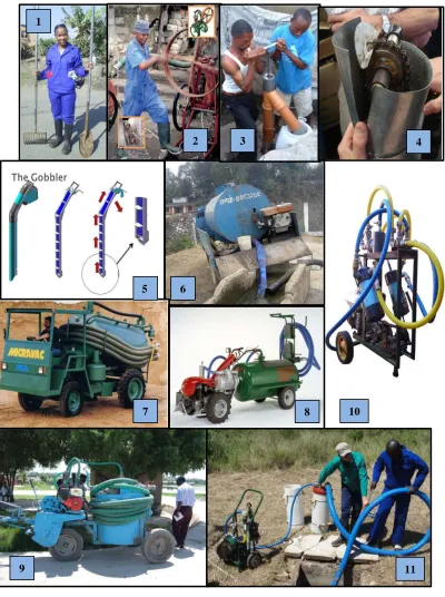
Pit latrine emptying technologies can be divided into three groups: manual, semi-mechanized, and fully mechanized. The manual group consists of buckets, shovels, and specialized scoops that require the user to manually remove the waste from the pit latrine. The waste is usually placed into containers for transport off site. The manual method is the cheapest form of pit latrine emptying but can be time consuming and exposes humans to the waste. Semi-mechanized pit emptying technologies utilize an apparatus to move the waste but are still powered manually (O’Riordan 2009). This group includes the MAPET system, which utilizes a hand powered piston pump that creates a vacuum in a tank mounted on a small pushcart (O’Riordan 2009). This system has been used for over two decades and has proven successful in certain conditions, such as the wet pits found in Dar es Salaam, Tanzania. Another prominent semi-mechanized technology that has been used in several developing countries is the Gulper, developed by Steve Sugden of the London School of Hygiene and Tropical Health. It is a very low cost and simple design that uses a human powered lever on the top of a pipe to move a foot valve up and down to draw the waste up and out of the pit through a wye fitting at the top of the pipe (O’Riordan 2009). It has proven successful with fairly liquid or low viscosity sludge but has had difficulties with the dense bottom sludge in wet latrines and with the entirety of the contents in dry latrines. Fully mechanized technologies use an engine or motor to power the mechanism used for emptying of the pit latrine. The most commonly known mechanism of this group is the vacuum tanker such as those often used in developed countries. They use a vacuum pump and a large
Manual
Long Handle Tools MAPET Gulper Nibbler Gobbler
Shovels, pitchforks, and scooping mechanisms with long handles
A manual pump and small tank mounted on pushcarts Manual hand pump Chain and Scoop mechanism Robust version of Nibbler
Good Fair Good Good Good
Poor Good Poor Poor Poor
High Low Low Low Low
Low Moderate Low Moderate Moderate
Low Moderate Low Moderate Moderate
Slow Moderate Slow Moderate Moderate
Low Moderate Low Moderate Moderate
Water-like Poor Good Good Poor Poor
Thick slurry Moderate Good Good Good Good
Dense sludge Good Poor Poor Moderate Moderate
Good Poor Poor Poor Poor
1,2 1,3 1,3 2,3 2,3
Vacuum Tanker Micravac Dung Beetle Vacutug NanoVac Evac Pit Screw Auger
A vacuum pump mounted on a motorized tanker
Micro vacuum tanker designed for uneven roads and poor access
Two wheeled tractor connected to small vacuum tanker
Original smaller vacuum tanker with 500L tank
Small vacuum system with piston pump Small vacuum system with vane pump
An auger or screw rotated within a pipe by a motor
Poor Fair Fair Fair Good Good Good
Good Good Good Good Good Good Poor
Low Low Low Low Low Low Low
High High High Moderate Moderate Moderate Moderate
High High High Moderate Moderate Moderate Moderate
Fast Fast Fast Moderate Moderate Moderate Moderate
High High High Moderate Moderate Moderate Moderate
Water-like Good Good Good Good Good Good Poor
Thick slurry Good Good Good Good Good Good Good
Dense sludge Poor Poor Poor Poor Poor Poor Good
Poor Poor Poor Poor Poor Poor Poor
Pit emptying times Description
Maneuverability within pit Access to most locations
Possibility of human contact with sludge Capital costs
Operating and maintenance costs
Semi-Mechanized
Capital costs
Operating and maintenance costs Source*
Design Complexity
Ability to empty high refuse Sludge emptying
capabilites
Fully Mechanized
Description
Access to most locations Maneuverability within pit
Possibility of human contact with sludge
Pit emptying times Design Complexity
Sludge emptying capabilites
Ability to empty high refuse
1
2 3 4
5 6
8 7
9 11
10
A.5.1 Pit Screw Auger
Another fully mechanized technology that has been developed by Dave Still, Mark O’Riordan and the Partners in Development team is the Pit Screw Auger. This design is very similar to the Extraction Auger and is based on the main principle of an auger being rotated within a pipe to lift the waste out of pit latrines. We were unaware of their research for a majority of our design and prototype development stage, but their findings, some very similar to ours, have proven very helpful as we move forward with our project.
The initial testing of the Pit Screw Auger on pig waste slurry was completed in a semi-mechanized fashion with the operator physically turning the auger. This yielded rotational speeds of only 50 to 60 rpm, which were not sufficient to achieve good output rates, so an electric motor was incorporated for higher speeds. They determined that there is a critical rotational speed that must be reached to achieve any flow and that above this rpm
flow rates would increase with rotational speed. For their tests, they found this critical speed to be 60 rpm for a setup with a 700 mm long pipe with a 125 mm diameter and a 100 mm diameter auger with 100 mm pitch. However, they saw no increase in flow rate when they increased the rotational speed from 60 to 120 rpm, which remained at 25 lpm.
newspapers, rags, and plastics. It performed very well in all of these tests with flow rates between 25 and 40 liters per minute although they did see a decrease to 5 lpm was observed as the pit near being emptied. However, when testing on an actual pit latrine, the Pit Screw Auger was unable to remove any waste as it became immediately jammed with trash present in the pit.
based on the problems they encountered and foresaw which are summarized below (Still and O’Riordan 2012):
- Trash in pits: remove as much trash as possible before emptying is started or develop a waste shredder to shred all the waste before it enters the pit.
- Reduce weight and improve maneuverability of system: Use a smaller diameter auger or have a system where the motor is separate from the control unit.
- Modularity: Having a unit that is assembled in sections may facilitate too much contact between the user and waste. Having different length of auger and
corresponding pipe for the different pit depths that may be encountered may be a good option.
- Extension: Having a system capable of lifting a total length of 2.8 m should work for most pits encountered.
- Storage and Transportation: Appropriate and ideal containers in addition to storage and transport methods should be identified.
- Cleaning: Develop equipment specifically for cleaning the auger system as it currently causes too much contact between the waste and user.
- Support: Develop a support that allows for good horizontal and vertical
maneuverability and a support that will allow the system to be manipulated inside a toilet superstructure if necessary.
APPENDIX B – Laboratory Testing
B.1 Formulation of Simulant Waste
Little data has been gathered on the mechanical properties of human waste, especially in pit latrines. It is known, however, that human waste exhibits thixotropic tendencies
implying that it becomes less viscous as more energy is put into the material (Mara 1984). A simulant waste was desired for laboratory testing that was analogous with the mechanical properties of human waste. Several formulations of simulant waste have been developed, to evaluate the use of human waste for biodegradation, energy production, etc.
In this project, simulant waste was prepared from a mixture of water and extra high yield bentonite clay (WYO-BEN Inc., Billings, MT). High yield bentonite is a powdered form of the clay that is an efficient viscosifier and mixes easily. A homogeneous mixture could not be easily prepared with the pellet form of bentonite.