Optimisation of Support Design of Tubes in a Sodium to Air Exchanger from
Thermal, Vibration and Seismic Loading Considerations
R.Srinivasan, S.Jalaldeen, A.Biswas, P.Selvaraj, P.Chellapandi and S.C.Chetal
Indira Gandhi Centre for Atomic Research, Kalpakkam-603102, India
ABSTRACT
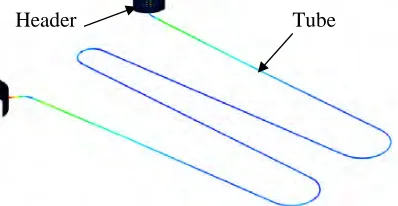
Sodium to air exchangers (AHX) are used in safety grade decay heat removal system of PFBR. Each tube of AHX is of serpentine type welded to pipe headers at either end. The sodium enters the tube bundle through the top header and leaves through the bottom one. The air enters the bottom of casing housing the tube bundle and header and leaves at the top. Each tube is having a small bend near the inlet header followed by finned portions joined by three intermediate U turns and a final bend near the outlet header. Each of these serpentine tubes needs to be supported from various loading considerations. More number of supports is favored to avoid flow induced vibration and seismic induced risks. However, the number of supports shall be minimum from thermo mechanical considerations. The number of supports is arrived at based on the analyses for various loadings. The analyses have been carried out using CAST 3M, a finite element code, developed by CEA, France Analyses indicated a minimum of six supports (one at either end of finned portions except near the header junction) is required to avoid fluid elastic instability under cross flow. Subsequent 3-D seismic analysis of the bundle (6 support design) resulted in unacceptable stresses under OBE and demanded 8 supports (additional support near the tube header junction). But high thermal stresses at the tube header junction are induced with this 8 support configuration. Analysis of a single tube with 8 supports treating the header junction as fixed boundary condition resulted in unacceptable thermal stresses. Hence a more realistic finite element model (tube using pipe elements along with a portion of header using shell elements) so as to include the flexibility offered by the header is employed for the analysis. Further a conservative stress relaxation procedure recommended in RCC-MR is used. The resulting strain limits and creep fatigue damage at the junction meets the criteria of French design code RCC-MR. The fatigue damage is 0.09 and creep damage is 0.72 for the design life of 40 Y. However the additional creep damage beyond 40Y is small (due to relaxation) and the cumulative creep damage is only 0.76 at the end of 60 Y. Thus the number of supports is decided as eight based on seismic loading and the integrity of tube header junction under thermal loading is demonstrated as per RCC-MR for this design.
INTRODUCTION
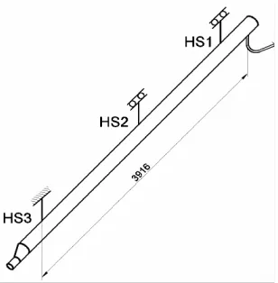
In 500 MWe Prototype Fast Breeder Reactor (PFBR) which is under construction at Kalpakkam, a dedicated safety grade decay heat removal system (SGDHR) is provided to cater the need of heat sink whenever the normal path is not available. In this system, the decay heat received by the radio active primary sodium is transferred to outside air through intermediate sodium. The intermediate sodium flows by natural convection. While decay heat exchanger (DHX) is used for transferring the heat from radioactive sodium to intermediate non radioactive sodium, an air heat exchanger (AHX) is employed for transferring heat from intermediate sodium to air. During normal operation of the plant, SGDHR is kept in poised condition by crack opening the dampers on airside and the associated airflow is 0.6 kg/s. The sodium enters the tube bundle through the top header and leaves through the bottom one. During normal operation, the heat loss through this circuit is negligible and hence the tube is at an isothermal temperature of ~ 820 K. During SGDHR operating conditions, the dampers are opened fully resulting in natural convection. The associated airflow rate is ~31.2 kg/s. Each tube of AHX is serpentine type (Fig.1) welded to pipe headers at either end. The tubes are subjected to cross flow of air and have risk of flow induced vibration. AHX is a class 1 component with seismic category as 1 and hence the integrity is to be ensured for OBE and SSE loadings. From flow induced vibration and seismic loading considerations more supports are favored for the serpentine tubes.
operation and it is essential to confirm the integrity of tube to header junctions from the creep fatigue damage considerations which demand flexibility and minimum number of supports. The headers are supported at three locations (Fig.2) along their length. One of the three supports in the header restrain the axial movement of header (fixed condition) while the other two have provision to allow axial thermal expansion of headers. The farthest tube from the fixed end of the header is subjected to maximum thermal loading (cyclic bending stress) during normal operation to shut down cycles. Even though both headers move almost equally, the tube is prevented from free movement if the tube is supported near the header junction thus inducing bending moments at the junction, which vary during different operating conditions.
The paper discusses the flow induced vibration analysis of a typical tube including acoustic vibration, seismic analysis of the bundle with header and support (3-D analysis), evaluation of realistic bending moment at the junction after considering the advantage of flexibility offered by the header and evaluation of creep-fatigue damage at the junction as per RCC-MR after considering stress relaxation. Finally the number of supports is finalized based on the above analyses and demonstration of integrity under all loadings is ensured.
CONFIGURATION AND GEOMETRICAL DETAILS
The casing housing the tube bundle and header are shown in Fig.3. The mean radius of header is 222.6 mm and its thickness is 12 mm. The major dimensions of serpentine tube are shown in fig. 1 and header support details in fig.2. The tube is having a small bend near the inlet header, finned portions joined by three intermediate U turns and a final bend near the outlet header. The tubes are arranged at a pitch of 106 mm perpendicular to airflow direction (Fig.1). The next row is arranged at a pitch of 70 mm (along airflow direction), but staggered by 53 mm in the transverse direction. The bare tube size is 38.1mm OD x 2.6 mm WT. The finned length between each U-bend is about 3050 mm in the straight portion. There are 5 fins per inch and each fin is 12.5 mm height x 1.219 mm thk. The header nozzle details are shown in Fig.3. A fillet radius of 20 mm, so as to reduce the stress concentration is provided at the header junction as shown in Fig.4.
Fig. 3 Casing schematic Fig. 4 Details of header nozzle
Fig. 2 Header support schematic
FLOW INDUCED VIBRATION ANALYSIS
Design analysis is carried out for FIV mechanisms namely vortex shedding, fluid elastic instability and acoustic resonance. Design check is carried out as per ASME Appendix: N [1] for vortex shedding and fluid elastic instability. Since design check for acoustic resonance is not covered in ASME Appendix: N, the same has been carried out as per TEMA [2] and published literature. It is assumed that the design criteria given in ASME Appendix: N and TEMA are applicable to the serpentine tube bundle of AHX. Effect of fin is considered for mass but not for stiffness. This has been confirmed by tests [3]. Added mass is 6.72 kg/m for finned portion and 3 kg/m for bare tube region (without fins). Corresponding to air flow of 31.2 Kg/s, the cross flow gap velocities and temperatures obtained from detailed thermal hydraulic analysis are used.
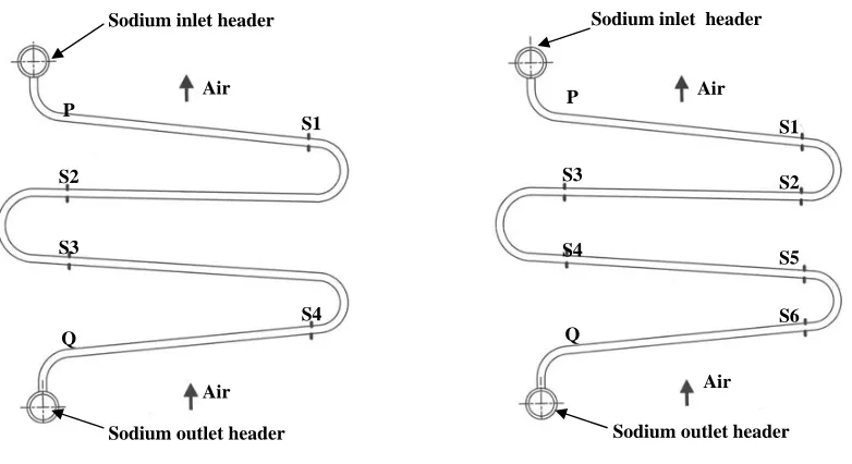
Minimum number of supports is favored from thermal loading consideration. Hence analysis is carried out with two different designs so that the minimum number of supports required to meet FIV can be arrived at; one with 4 supports (Fig 5) and another with 6 supports (Fig 6). The bend configurations vary for the inner, middle and outer rows and the variation in natural frequency among them is found to be very small (~0.1 Hz). The lowest of the three frequencies is taken for the analysis.
For gaseous systems lock-in synchronization is suppressed, in general, by the criteria on reduced damping (2.0 mδ / ρ D2 > 64). With respect to fluid elastic instability, the critical velocity has been computed as per ASME Appendix N. The recommended formula in ASME is
VC / (fn D) = c [mδ /ρ D2] a where C=3.3, a=0.5 for the entire mass damping parameter (mδ /ρ D2) range and 0.5% damping (δ = 0.03) for gaseous shell side fluids. The fundamental frequency is 3.7 Hz for the four support case and 5.2 Hz for the 6 support case. Typical mode shapes are given in fig.7 and fig.8. .
Fig 5 Configuration with 4 supports Fig.6 Configuration with 6 supports Air
Sodium outlet header P
S3
S4
Q
S1
S2
S5
S6
Air Sodium inlet header
Air Sodium inlet header
Air
Sodium outlet header S1
S4 P
S2
S3
Q
Fig.8 Mode shape with 6 supports – 5.2 Hz Fig.7 Mode shape with 4 supports – 3.9 Hz
Since the critical velocity is independent of diameter; bare tube OD (fin root diameter) is used in the calculation. Table: 1 shows the mean cross flow velocity and the critical velocity for four passes. From the table, it can be seen that four support case is not meeting in each of the four passes whereas the critical velocity is higher than the cross flow velocity for each pass for the configuration with 6 supports. Hence 6 support configuration (Fig.6) is recommended from fluid elastic instability considerations. Further analysis is continued with 6 support case.
Table: 1 Mean cross flow velocity and the critical velocity for four passes
Critical velocity (m/s) Location Cross flow
Velocity m/s
Density of
air (Kg/m3) mδ/ρD 2
4 supports (3.7 Hz) 6 supports (5.2 Hz)
Pass 1(hot end) Pass 2 Pass 3
Pass 4 (cold end)
8.6 7.8 6.6 5.9 0.5576 0.65 0.8152 1.1277 249.1 213.7 170.3 123.1
7.3 < 8.6 6.8 < 7.8 6.1 < 6.6 5.2 < 5.9
10.3 > 8.6 9.5 >7.8 8.5 > 6.6 7.3 > 5.9
SEISMIC ANALYSIS
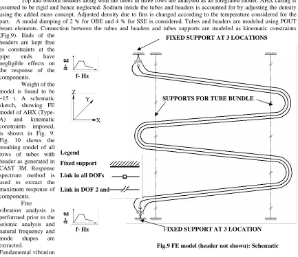
Top and bottom headers along with the tubes in three rows are analysed as an integrated model. AHX casing is assumed to be rigid and hence neglected. Sodium inside the tubes and headers is accounted for by adjusting the density using the added mass concept. Adjusted density due to fins is changed according to the temperature considered for the part. A modal damping of 2 % for OBE and 4 % for SSE is considered. Tubes and headers are modeled using POUT beam elements. Connection between the tubes and headers and tubes supports are modeled as kinematic constraints (Fig.9). Ends of the
headers are kept free as constraints at the pipe ends have negligible effects on the response of the components.
Weight of the model is found to be ~15 t. A schematic sketch, showing FE model of AHX (Type-A) and kinematic constraints imposed, is shown in Fig. 9. Fig. 10 shows the resulting model of all rows of tubes with header as generated in CAST 3M. Response spectrum method is used to extract the maximum response of components.
Free
vibration analysis is performed prior to the seismic analysis and natural frequency and mode shapes are extracted.
Fundamental vibration
mode of AHX is 5.11 Hz which is in-plane bending of inner row of tubes. Nearby modes of 5.15 Hz and 5.19 Hz show the in plane bending of outer row of tubes and middle row of tubes respectively. This is same as the first vibration mode of individual tube discussed earlier. Modes up to 33 Hz are extracted to perform response spectrum analysis.
FIXED SUPPORT AT 3 LOCATIONS
FIXED SUPPORT AT 3 LOCATION
Fig.9 FE model (header not shown): Schematic Z
Y
X
SUPPORTS FOR TUBE BUNDLE
Legend
Fixed support
Link in all DOFs
Link in DOF 2 and 3
a- g
f- Hz
a- g
f- Hz
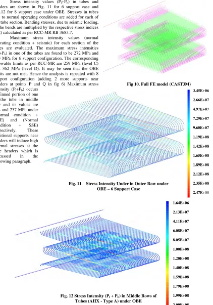
Stress intensity values (Pl+Pb) in tubes and headers are shown in Fig. 11 for 6 support case and Fig.12 for 8 support case under OBE. Stresses in tubes due to normal operating conditions are added for each of the tube section. Bending stresses, due to seismic loading, in the bends are multiplied by the respective stress indices (B2) calculated as per RCC-MR RB 3683.7.
Maximum stress intensity values (normal operating condition + seismic) for each section of the tubes are evaluated. The maximum stress intensities (P1+Pb) in one of the tubes are found to be 272 MPa and 263 MPa for 6 support configuration. The corresponding allowable limits as per RCC-MR are 259 MPa (level C) and 362 MPa (level D). It may be seen that the OBE limits are not met. Hence the analysis is repeated with 8 support configuration (adding 2 more supports near headers at points P and Q in fig 6) Maximum stress intensity (Pl+Pb) occurs
in finned portion of one of the tube in middle row and its values are 234 and 237 MPa under (Normal condition + OBE) and (Normal condition + SSE) respectively. These additional supports near headers will induce high thermal stresses at the tube headers which is discussed in the following paragraph.
Fig 10. Full FE model (CAST3M)
Fig. 11 Stress Intensity Under in Outer Row under OBE – 6 Support Case
3.45E+06
2.66E+07
4.97E+07
7.29E+07
9.60E+07
1.19E+08
1.42E+08
1.65E+08
1.89E+08
2.12E+08
2.35E+08
2.47E+08
Fig. 12 Stress Intensity (Pl + Pb) in Middle Rows of Tubes (AHX - Type A) under OBE
1.64E+06
2.13E+07
4.11E+07
6.08E+07
8.05E+07
1.00E+08
1.20E+08
1.40E+08
1.59E+08
1.79E+08
1.99E+08
2.09E+08
THERMAL STRESS ANALYSIS
The headers are supported at three locations along their length. One of the three supports in the header restrain the axial movement of header (fixed condition) while the other two have provision to allow axial thermal expansion of headers. The farthest tube from the fixed end of the header (3916 mm in Figure 4) is considered for the analyses. Even though both headers move almost equally, the tube is prevented from free movement by the tube support nearest to the header junction thus inducing bending moments at the
junction, which vary during different operating conditions.
One tube along with a small portion of the header (Fig. 13) is modeled in CAST 3M. The tube is modeled using piping elements whereas the header is modeled using thin shell element. The thermal expansion of header from the fixed end to the tube location is (expansion of 3916 mm long header is 25.6 mm at 820 K and 7.9 mm at 473 K) fed as an input. Including the header portion in the model accounts for the advantage of flexibility offered by the header and the realistic value of bending moment at the junction (ML) has been evaluated as 910 N-m
Junction Stresses
The local stresses at the junction including stress concentration (function of fillet radius) are obtained as per WRC bulletin 107 [8] using the forces and moments obtained from the global analysis. Applied (longitudinal) bending moment ML at the tube end induces a longitudinal tensile stress σx in the upper surface of header at the junction.
σx = Kn Nx/T + Kb 6Mx/T2 where the stress concentration factors for membrane (Kn) and bending (Kb) stresses are 1.4 and 1.2 for r/T = 1.7. σx has been calculated using Nx = 0.29 ML/Rm2β and Mx = 0.096ML/Rmβ. Here Rm is the mean radius of the header and β is the attachment parameter: β = 0.875 ro/Rm = 0.07. The shell parameter is r =Rm/T = 20 from ref. [8]. This gives σx = 321 MPa (after considering radial expansion of header) which is less than 38m and the strain limits are also checked as per RCC-MR.
CREEP- FATIGUE DAMAGE AT THE JUNCTION
The secondary creep law is used as the time for primary creep for the induced stress of 300 MPa is small compared to operating period as shown below.
Time for primary creep tfp= C3σn3 where σ = 321/2 =160.5 MPa, C
3 = 9.0434 x 10¹⁷ &n3 = -6.7532 resulting in tfp = 1150h ≤ 2.63 x 10⁵ h. So the strain rate due to secondary creep has been used in the creep-fatigue damage calculation.
Fatigue Damage Calculation
Totally 861 load cycles (n) between normal operations to shut down is considered for the fatigue damage in the design life of 40 years. The creep strain per cycle is obtained by considering the hold time of 305 h (total design life of 2.63 x 10⁵ h divided into equal periods over 861 cycles). The elastic plastic strain (computed as per RCC-MR procedure from elastic stress results) plus creep strain (corresponding to 305 h hold time) is 0.22 %. The allowable number of cycles (N) is obtained as 10000 from the design fatigue curve for the material corresponding to the strain range of 0.22%. The resulting fatigue damage is 0.09 (V = n/N) for n=861.
Creep Damage Calculation
The junction also experiences a creep damage due to life time exposure of about 2.63 x 10⁵ h at 820 K with primary stress kept constant and the secondary stress intensity getting relaxed with secondary creep strain. During creep, secondary stresses σ generally arising from the local bending moment at the tube-header junction as a result of compatibility condition get relaxed, but primary stresses (Pm + φ Pb) in the header generally arising from pressure do not. Since part of the secondary stress intensity in the junction may not relax, RCC-MR recommends a follow up factor ‘Cr ‘of 3.0. Accordingly σ = -E/(100Cr) and dεs/dt= Cσn. This gives σ = 1/(At + B)1/n-1 where
A= E(n-1)C/(100Cr) and B=1/σkn-1.
The secondary stress intensity range Vs time so computed is plotted in Fig. 14. The cumulative creep damage (W) is the sum Σ∆t/tr assuming that σ remains constant for a time ∆t. tr is the rupture life corresponding to Sr’ =Sr/0.9 where Sr = (mean P + Ks* ∆σ) and the division by 0.9 is factor of safety applied on stress. From the minimum stress to rupture curve allowable time is obtained for each time interval considered and the creep damage for that interval
Tube
Header
Fig. 13 Finite element model
is computed as the ratio of time interval considered to the allowable time. Summation of the damage ratio for each interval over the design life results in the cumulative creep damage.
As the secondary stress intensity is sharply relaxing with time, it is essential to consider smaller time intervals for creep damage evaluation (particularly in the initial period). Use of larger time interval in the analysis results in a conservative value of damage. As the time interval is reduced (life is divided into more number of intervals), the cumulative damage reduces and converges to a smaller value. If damage is computed with 1000 h interval time steps, the cumulative creep damage will be ~1.3 for 40 year design life i.e more than the allowable value of unity but the value is 0.74 for 50 h interval and 0.72 for 5 h or 0.5 h interval. The converged value of cumulative creep damage up to 60 year design life is shown in Fig 15.
The fatigue damage of 0.09 and creep damage of 0.72 lie within the bilinear creep-fatigue damage interaction diagram given in RCC-MR [9] and hence 40 year design life is comfortably met. It may be seen that the cumulative creep damage is only 0.76 for 60 years indicating that the component can have a life of 60 years. This is due to the fact that the secondary stress intensity have relaxed to 60 MPa in 40 years and hence the additional creep damage after 40 years is small.
Similarly, the creep strain to be considered for fatigue damage evaluation is also negligible after 40 years. Hence the total elastic plus plastic strain is only 0.17% resulting in a net fatigue damage of 0.1 for 60 years. The creep-fatigue damage for 60 years is just on the limiting line as can be seen in figure.16.
CONCLUSION
The sodium to air heat exchanger of PFBR has been analysed for flow induced vibration, seismic and thermo mechanical loadings. The analysis has been carried out using CAST 3M, a finite element code, developed by CEA, France. A minimum of 6 supports is needed from fluid elastic instability considerations. The seismic analyses of the headers and the tube bundle using 3-D model in CAST 3M demanded two additional supports. Thermal analysis of a tube with 8 supports using pipe element model fixed at both ends resulted in unacceptable thermal stresses. Hence the analysis is repeated with more realistic model in which the tube is modeled using pipe elements along with small portion of header modeled as thin shell element. The thermal shocks are found to be not important but the cyclic loading (861 cycles with a hold time of 305 h) between two steady state namely normal operation and shut down is considered for fatigue loading. The creep damage is evaluated after considering possible stress relaxation of secondary stresses with the follow up factor of 3 recommended in French design code RCC-MR. The creep-fatigue interaction rule of RCC-MR is met with comfortable margin for 40 year design life and indicates that the component can have a life of 60 years.
REFERENCES
1. ASME section III Div. 1 Appendix: N ‘Dynamic Analysis Method’, 2001.
2. TEMA, ‘Standards of the Tubular Exchanger Manufacturers Association’, 8th edition, 1999. 3. ‘Effect of fins in the tubes of AHX (type A)’, PFBR/34160/DN/1015/A- Internal Document.
Fatigue Damage - V
Creep
Da
mag
e
-W
Fig.16 Creep –Fatigue Interaction 60 Y (0.10, 0.76)
40 Y (0.09, 0.72) Fig. 15 Creep damage Vs time
Time in hours
S
e
condar
y
s
tr
ess
in
ten
s
ity
ran
g
e
(MP
a)
Fig. 14 Stress relaxation with Cr =3
σ = 1/(At + B)1/n-1
4. ESDU, 'Engineering Science Data, Heat transfer sub series vol.9, Heat Exchangers: Flow induced vibration', ESDU Data Item No.88028, 1988.
5. R.D.Blevins, 'The effect of sound on Vortex shedding from circular cylinders', Journal of fluid mechanics,161, 1985, pp.217-237
6. Robert D.Blevins, 'Flow-Induced Vibration', Second Edition, Van Nostrand Reinhold, New York, 1990. 7. Parker,R. , 'Acoustic resonances in passages containing banks of heat exchanger tubes' , Journal of sound and
Vibration, Vol.75, No.2, 1978, pp.245 - 260
8. K.R.Wichman, A.G.Hopper, and J.L.Mershon,”Local stresses in spherical and cylindrical shells due to external loadings”, WRC Bulletin No 107, Aug.1965, revised Mar.1979.
9. RCC-MR subsection RB for class 1 components, design and construction rules for mechanical components of FBR nuclear islands, 2002, AFCEN, Paris, France.