Shift in Position of Centre of Mass and Centre
of Rigidity with Change in Symmetry of a
Building
Md. Malik Burhanuddin S 1, N Punith 2, Naresh Kumar B G 3, Prakash T M 4
P.G. Student, Department of Civil Engineering, PES College of Engineering, Mandya, Karnataka, India1
Assistant Professor, Department of Civil Engineering, MITM, Mandya, Karnataka, India2
Professor, Department of Civil Engineering, MITM, Mandya, Karnataka, India3
Associate Professor, Department of Civil Engineering, PES College of Engineering, Mandya, Karnataka, India4
ABSTRACT: Seismic analysis of structures has always been an important branch of civil engineering in general and
structural engineering in particular. Also the studies conducted regarding the effect of seismic forces on structures with respect to variations in structural properties like mass regularity, plan regularity.., etc. show that there is a large scope of research in the said field. With these points in mind this research in the field of seismic analysis of structures with plan-irregularities and varying diaphragm conditions saw a start. This document discusses a part of the ongoing research work of the authors. The paper particularly discusses the variation in positions of centres of mass and centres of rigidity in the various structural models considered in the study with varying conditions of plan symmetry under the action of incremental horizontal seismic forces along both mutually perpendicular directions. The analysis tool used in this research is ETABS-2015 and the method of seismic analysis used is Non-linear Static Analysis also known as Pushover Analysis.
KEYWORDS:Seismic Behaviour, Pushover Analysis, Plan Irregularities, Centre of Rigidity, Centre of Mass.
I. INTRODUCTION
the static and dynamic nature of the analysis. In general, linear procedures are applicable in cases where the structure is expected to remain elastic throughout the analysis or in cases of uniformly exhibited non-elastic behaviour. With the increase in the inelastic demands of the performance objectives of a structure, the uncertainty with linear procedures increases to a great extent; usually requiring a high level of conservatism in assumptions of demand and acceptability criteria to avoid unsatisfactory performance and hence generating a need for nonlinear procedures.
Also another point of importance to be considered is that even though dynamic analysis methods are more efficient compared to static analysis methods, the cumbersome nature of these analysis methods discourages one from using them. Thus the only option left for a good quality non-linear seismic analysis is the non-linear static analysis method which is also known as "pushover" analysis.
IS 1893(Part-1):2002, the criteria for earthquake resistant design of structures, majorly classifies the irregularities found in the structure into 2 types, i.e. plan irregularities and vertical irregularities. Of these, this research focuses only on the effect of variations in plan configuration on the seismic behaviour of the structure with respect to change in positions of the centre of mass and centre of rigidity.
The centre of mass is the point where the entire mass of the floor acts and centre of rigidity is the where the entire stiffness of the building acts. Mass is majorly contributed by beams and slabs where stiffness is contributed by the columns and shear walls of the building.
II. METHODOLOGY
This section discusses the methodology followed in the course of the research work and the parameters which have influenced the various choices made in the due course of the research.
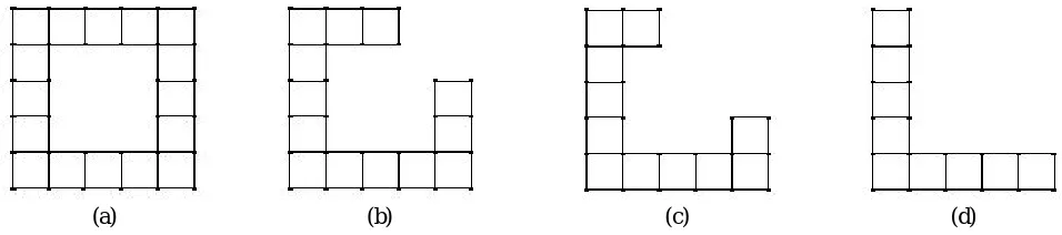
The analysis tool used in this research is ETABS-2015 and the method of seismic analysis used is Non-linear Static Analysis also known as Pushover Analysis. The models used for analysis include buildings with varying plan symmetry. The first model is a symmetric shaped model (fig.1(a)). The second model (fig.1(b)) is made by removing a corner and two adjacent units (one unit represents a 5mx5m square on the structural plan) from the symmetric model and the third model (fig.1(c)) is made by improvising on the second model by further removing one unit from either side of the structure in model no. 2 and finally model no. 4 which is an asymmetric 'L' shaped model (fig.1(d)) is obtained from model no. 3 as model no. 3 was obtained from model no. 2. All the four models consist of 5 floors each (G+4), with the floor heights being 3.5m each with the dimensions of both columns and beams being fixed at 230mm x 450mm for all the four cases. The column positions have so been fixed, that the spans of all the beams in both X and Y directions are kept same and equal to 5m. The loading conditions for all the four models are the same. All the four models have been analysed for rigid diaphragm condition only. The column position layouts for all the four models, i.e. models 1,2,3 and 4 used in the analysis are as shown in figures 1 (a),(b),(c) and (d) respectively.
(a) (b) (c) (d)
Fig. 1. Column Position Layouts for (a) Model 1, (b) Model 2, (c) Model 3, (d) Model 4
and rotate since behavior is coupled both in plan and along height. As a function of structural properties, center of rigidity is independent of loading.
For a given floor diaphragm, center of rigidity is calculated through the following process:
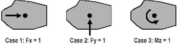
Case 1 applies a global-X unit load to an arbitrary point, perhaps the center of mass, such that the diaphragm rotates Rzx; Case 2 applies a global-Y unit load at the same point, causing rotation Rzy; Case 3 applies a unit moment about global-Z, causing rotation Rzz. These three load cases are shown in Figure 2.
Center of rigidity (X,Y) is then computed as X = -Rzy / Rzz and Y = Rzx / Rzz.
During analysis, ETABS automatically calculates this coordinate for each floor diaphragm. The diaphragm assignment must be present in the model
Fig. 2. Centre of rigidity under different forces (courtesy-Computers and Structures Inc. website)
III.ANALYSIS
The software package ETABS-2015 was used throughout the course of research for the design and analysis of the building models. ETABS-2015 is an integrated structural analysis and design software package and is an improved version of the earlier ETABS software packages.
The building systems were directly modelled onto the ETABS modelling screen. Then the buildings were subjected to the usual dead and live load sets as per the Indian standards. This is to be done in order to check the capacity of the preliminarily fixed dimensions of the structural members. If all the members pass the design check, then the next part of analysis i.e. seismic analysis is carried out or else the member sizes are revised and the procedure is taken forward. Then the static non-linear load patterns and load cases required for carrying out pushover analysis are defined for both
X and Y directions. After the member sizes are fixed, all the columns and beams (frame members) are assigned hinges based on the hinge properties from tables given in ASCE 41-13. After this the model is checked for errors and then finally it is analyzed under the action of lateral pushover loads applied under displacement control method. After the analysis is complete, the push over results like: the push over curve, the deflected shape of the model along with the formation of hinges, force and moment plots,.., etc. may be reviewed. But the scope of research of this paper only includes the study of change in positions of centres of mass and centres of rigidity with respect to increasing asymmetry.
In ETABS by default the centre of rigidity is calculated as the stiffness centroid within a floor-diaphragm plan. When the centre of rigidity is subjected to lateral loading, the floor diaphragm will experience only translational displacement and the other levels are free to translate and rotate since behavior is coupled both in plan and along height. As a function of structural properties, center of rigidity is independent of loading.
IV.RESULTS AND DISCUSSIONS
rigidity with respect to X and Y directions for the same. In the tables XCM and YCM represent the location of centre of mass with respect to X and Y directions respectively and similarly XCR and YCR represent the location of centre of rigidity with respect to X and Y directions respectively. Also the charts 1 and 2 show the plots of locations/positions of centres of mass and centres of rigidity for models 1, 2, 3 and 4 respectively. Both the plots i.e. charts 1 and 2 have been plotted with respect to the location of the centres (i.e. centres of mass and rigidity) along X and Y directions for the respective models.
Table 1. Location of centre of mass for different models
MODEL TYPE
LOCATION OF CENTRE OF
MASS(m)
XCM YCM
MODEL 1 12.5 12.5
MODEL 2 10.7496 10.7518
MODEL 3 9.4831 9.4889
MODEL 4 8.2087 8.2212
Table 2. Location of centre of rigidity for different models
MODEL TYPE
LOCATION OF CENTRE OF RIGIDITY(m)
XCR XCR
MODEL 1 12.5 12.5
MODEL 2 10.8172 10.8172
MODEL 3 9.3618 9.3618
Chart 1. Location of Centre of Mass With Respect To X and Y Axes
Chart 2. Location of Centre of Rigidity With Respect To X and Y Axes
From the chart 1 and chart 2 it can be observed that the centre of mass and centre of rigidity goes on reducing from model 1 to model 4 as the building changes from plan symmetric to plan asymmetric.
V. CONCLUSION
REFERENCES
[1] Anagnostopoulos S. A., Kyrkos M.T. and Stathopoulos K.G., " Earthquake Induced Torsion in Buildings: Critical Review and State of the Art ", Advances in Structural Engineering and Mechanics(ASEM-13), September 8-12,2013.
[2] A. Lucchini, G. Monti and S. Kunnath, "A Simplified Pushover Method for Evaluating the Seismic Demand in Asymmetric-Plan Multi-Storey Buildings", 14th World Conference on Earthquake Engineering October 12-17, 2008.
[3] Duggal S K, "Earthquake Resistant Design of Structures", Oxford University Press, 2009.
[4] IS 1893 (Part 1): 2002," Criteria for earthquake resistant design of structures", Bureau of Indian Standards, New Delhi, India.
[5] Kazem Shakeri , Karim Tarbali and Mohtasham Mohebbi, " An adaptive modal pushover procedure for asymmetric-plan buildings", Engineering Structures, March 2012.
[6] Kenji Fujii, Yoshiaki Nakano and Yasushi Sanada, " Simplified Nonlinear Analysis Procedure For Asymmetric Buildings ", 13th World Conference on Earthquake Engineering , Paper No. 149, August 1-6, 2004.
[7] Stathopoulos K. G. and Anagnostopoulos S. A., "Earthquake Induced Inelastic Torsion in Asymmetric Multistory Buildings", 13th World Conference on Earthquake Engineering, Paper No. 558, August 1-6, 2004.
[8] Vojko Kilar and Peter Fajfar "Simple Push-Over Analysis of Asymmetric Buildings" Earthquake Engineering & Structural Dynamics, February 1997.
BIOGRAPHY
Mr. Md. Malik Burhanuddin S was born in Mysore, India. He graduated with B.E., in Civil Engineering under VTU-Belgaum, from MIT-Mysore in the year 2015,and is currently pursuing Master of Technology in Computer Aided Design of Structures (CADS) at PESCE-Mandya.
Mr. N Punith was born in Mysore, India, on 21st Oct 1987. He did his B.E. in Civil Engineering from Dr.AIT, Bangalore and M.Tech.(Structures) from SJCE, Mysore. Currently pursuing the Ph.D. under VTU. He has more than 6 years of teaching experience and is presently working as assistant professor in MIT-Mysore.
Dr. Naresh Kumar B G was born in Mandya, India on 21st May 1958. He did his M.E. (Structures) from University of Roorkee (1987) and obtained his Ph.D. from IIT - Roorkee(1996). He has more than 36 years of teaching experience and is presently working as professor and principal in MIT-Mysore.