Design, Development and Analysis of Shell
and Tube Heat Exchanger Using
Computational Fluid Dynamics
M. A. Boda1, A. B. Vannam2, S. S. Deshetti3, M. A. Gavade4
Assistant Professor, Department of Mechanical Engineering, V.V.P.I.E.T., Solapur, MH. India.1
U. G. Students, Department of Mechanical Engineering, V.V.P.I.E.T., Solapur, MH. India.2, 3 & 4
ABSTRACT: In the textile industry hot water is required for dyeing process so a boiler is used to heat the water. To increase the efficiency of boiler supply water should be preheated. So to pre-heat the supply water shell and tube heat exchanger is can be used. After dyeing process the left hot water is drained into sewage, this hot water can be utilized to pre-heat the supply (incoming) water of boiler. The heat exchanger is designed with standard procedure and then according to the dimensions heat exchanger is manufactured and with the same values a CFD model is generated. The experimental results and CFD results were compared and some conclusions were made.
KEYWORDS: design of heat exchanger, shell & tube heat exchanger, CFD analysis, development, performance evaluation
I. INTRODUCTION
A heat exchanger is a device that is used to transfer thermal energy between two or more fluids, through a solid surface and a fluid, or between solid and fluid, at different temperatures and in thermal contact. There are usually no external heat and work interactions. In general, if the fluids are immiscible, the separating wall may be eliminated, and the interface between the fluids replaces a heat transfer surface, as in a direct-contact heat exchanger [3]. A heat exchanger consists of heat transfer elements such as a core or matrix containing heat transfer surface, and fluid distribution elements such as headers, manifolds, tanks, inlet and outlet nozzles or pipes, or seals. Usually, there are no moving parts in a heat exchanger [3, 11].
II. LITERATURE REVIEW
through the periphery of strip experiencing a centrifugal force due to which velocity rate is increased and heat transfer rate increases. Ananth, S., et. al. [6] Analysis of overall heat transfer coefficient and effectiveness in split flow heat exchanger using nano fluids is done in this,different fluids are used for cooling like tap water, distilled water, mixture of ethylene glycols and water for experiment. Results are compared; result shows that using mixture as cooling fluid gives more heat transfer rate. Shinde, S., S., et. al. [7] designed shell and tube HE in which helical baffles are introduced in shell by 20o inclination angle due to this velocityof fluid increases because of this heat transfer rate gets increased. The velocity is increased by increasing inclination angle. Lunsford, K., M., et. al. [8] discussed about enhancement of heat exchanger, the fouling factor plays vital role for reducing performance of heat exchanger by creating resistance to heat transfer which can be reduced by providing radial flow from the centre of the wall, due to this material deposition on wall get decreases. Ahire, S., et. al.[9] constructed and analysed counter flow helical coil
heat exchanger. Helical coil shape is given to tubes. They found that centrifugal force due to curvature of tubes results in secondary flow development, this secondary flow enhances heat transfer rate. Conclusion of their work was helical coils are efficient in low Reynolds number.Zhang, J., F., et. al. [10] for developing a shell and tube heat exchanger with middle overlapped baffles, a comprehensive simulation model by using commercial code FLUENT and grid generation program GAMBIT. The validation of 40o helix angle is performed and results which got those shown a reasonable agreement with available experiment data. Kundu, B., [12] designed Un-baffled shell and tube heat exchanger with attachments of longitudinal fins having trapezoidal profile; a parametric variation studied by Kern’s method. While keeping the outer shell diameter is a constant along with all other constraints, the HEAT TRANSFER rate in trapezoidal fins was lesser than rectangular cross section of a heat exchanger. Maheshwari, D., A., and Trivedi, K., M., [13] they did experimental investigation of U tube HE using plain and corrugated structure of tube. Corrugated tube heat exchanger gives more heat transfer coefficient and heat transfer rate than straight heat transfer tube heat exchanger.Logeshan, K., L., et. al.[14] studied how to increase fluid velocities which results in large heat transfer coefficient and consequently less heat transfer area. Guo, J., et. al.[15] developed a new heat exchanger based on second law of thermodynamics. In this approach, modified entropy generation amount which can avoid entropy creation is taken as the objective function. Boda, M., A., et. al. [19] according to this article daily 840 m3 waste water is released from the textile industry this waste water is left in sewage after filtration is done.
III. DESIGN OF HEAT EXCHANGER
The design part it plays a very important role in any system. The detailed design of a shell and tube heat exchanger is discussed below, in that some data considered and assumed wherever it is required.
3.1 Considerations for Heat Exchanger [20, 21]
i. Temperature- The cold inlet temperature is taken as 29o C and the cold outlet temperature is 40oC. The hot inlet temperature is taken as 60oC.
ii. Mass flow rate- For cold water is taken as 0.015 and hot water is 0.030kg/s. iii. Tube- Four copper tubes 0.0127meter diameter is used.
3.2 Assumptions [20, 21]
i. The fluid flow and heat transfer processes are turbulent and in steady state. ii. The natural convection induced by the fluid density variation is neglected. iii. The tube wall temperature kept constant in the whole shell side.
3.3 Design of shell and tube heat exchanger component
3.3.1 Preliminary Stage [16, 17, 18]
1. Heat transfer rate
p
QmC T 0.015 4179 (29 40) 690 2. Calculate over all heat transfer coefficient
Assume over all heat transfer coefficient from the table given below [18, 22] Uo=1300
3. Calculate log mean temperature difference
( ) ( ) (60 40) (55 29) 22.86 60 40
ln ln 55 29
hi co ho ci
lm
hi ci
ho ci
T T T T
T T T T T
4. Calculate Provisional length 690 0.023 1300 22.86 o o lm Q A U T
5. Calculate dimensions of heat exchanger
To calculate shell diameter and no. of tubes for single pass take
CTP=0.93 this value is for single tube pass, CL=1 this value is for 45o and 90o degree tube layout 2.54 2 1.27 T o P PR d
2 1 0.023(2)2 0.01270.637 0.637 0.062
0.93 0.15
o o
s
A PR d
CL D CTP L Assume L=0.15
2 22 2 2 2
0.93 (0.062)
0.785 0.785 4
1 (2) (0.0127)
s t o D CTP N
CL PR d
6. B 0.6DS 0.6 0.060 0.036
Now rate the heat exchanger according to TEMA standard and recalculate the length of heat exchanger, from Table number 8.3, page number 293, [18]
3.3.2 Secondary Stage [16, 17, 18]
7. Calculate heat transfer coefficient Shell side heat transfer coefficient
2 2
2 24 / 4 4(2.54 0.0127 / 4)
0.051 0.0127 T o e o P d D d
0.0254 0.0127 0.0127
T o
CP d
3
0.060 0.0127 0.036
Nu 0.36
Re 0.55 pr 0.330.36(3039.2)0.55(2.99)0.33 42.58...for2 10 3Re 106
42.58 0.651 543 0.051 u o e N K h D
Tube side heat transfer coefficient, Take
C
p,, ,P
r at cold fluid mean temperature from appendix Table B.2 [15]2 2 4 0.0127 4 5 10 4 4 i t tp d N
A
4 0.015
0.033 998 5 10
t t tp m v A
998 0.033 0.012 563 0.618 i e vd R
3 3 0.33 3 3 0.33
(3.66 1.61 ( / )) 3.66 1.61 (563 5.57 0.012 / 0.15)) 10
u e r i
N R P d L
10 0.651 501 0.012 u i i N K h d
Over all heat transfer coefficient for fouled surface
1
230 ln / 1
2
f
o ft o o i
o
fo
i i i o
U
d R d d d
d
R
d h d K h
Take
R
ftandR
fo from table of fouling factor as 0.000176 for tap water. 8. To calculate tube length690 0.11 230 22.86 of of lm Q A U T 0.11 0.62 0.0127 4 of o t A L d N
9. Calculating number of baffles
0.61
1 1 16 0.036 b L N B
IV. EXPERIMENTAL SET-UP
Fig1: Actual Experimental Set-Up
The above figure shows pictorial view of shell and tube heat exchanger’s experimental setup. This contains shell, tube and baffles inside the shell, temperature indicator, geyser, inlet-outlet piping system, etc.
V. CFD ANALYSIS
a) Cold outlet
2. b) Hot outlet
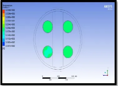
Fig 2: Temperature Variation in Counter Flow Arrangement, were mass flow rate of shell side and tube side are 0.030kg/s and 0.015kg/s respectively.
The figure 2 shows a temperature variation of shell and tube heat exchanger of counter flow arrangement. Figure 2a shows cold outlet temperature at mass flow rate of 0.030 kg/s and figure 2b shows hot outlet temperature at mass flow rate of 0.015 kg/s. The colour indicates the temperature range and colour difference shows temperature variation.
3. b) Hot outlet
Fig. 3: Temperature Variation in Parallel Flow Arrangement, were mass flow rate of shell side and tube side are 0.030kg/s and 0.015kg/s respectively
The figure 3 shows a temperature variation of shell and tube heat exchanger of parallel flow arrangement. Figure 3a shows cold outlet temperature at mass flow rate of 0.030 kg/s and figure 3b shows hot outlet temperature at mass flow rate of 0.015 kg/s. The colour indicates the temperature range and colour difference shows temperature variation.
CFD Results
The table numbers 1 to 4 are observation tables of CFD results.
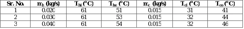
Table 1: Observation from CFD of temperature with respect to mass flow rate in shell side in counter flow arrangement
Sr. No. mh (kg/s) Thi (o C) Tho (o C) mc (kg/s) Tci (o C) Tco (o C)
1 0.020 61 50 0.015 31 42 2 0.030 61 52 0.015 31 43 3 0.040 61 53 0.015 31 45
The table 1 is Results of Counter flow arrangement were mass flow rate of shell side fluid (hot water) is varying from 0.020 kg/s, 0.030 kg/s and 0.040 kg/s but tube side fluid (cold water) is constant at 0.015kg/s.
Table 2: Observation from CFD of temperature with respect to mass flow rate in tubes side in counter flow arrangement
Sr. No. mh (kg/s) Thi (o C) Tho (o C) mc (kg/s) Tci (o C) Tco (o C)
1 0.030 62 57 0.005 32 55 2 0.030 62 52 0.015 32 43 3 0.030 62 51 0.025 32 42
The table 2 is Results of Counter flow arrangement were mass flow rate of tube side fluid (cold water) is varying from 0.005 kg/s, 0.015 kg/s and 0.025 kg/s but shell side fluid (hot water) is constant at 0.015kg/s.
Table 3: Observation from CFD of temperature with respect to mass flow rate in shell side in parallel flow arrangement
Sr. No. mh (kg/s) Thi (o C) Tho (o C) mc (kg/s) Tci (o C) Tco (o C)
The table 3 is Results of Parallel flow arrangement were mass flow rate of shell side fluid (hot water) is varying from 0.020 kg/s, 0.030 kg/s and 0.040 kg/s but tube side fluid (cold water) is constant at 0.015kg/s.
Table 4: Observation from CFD of temperature with respect to mass flow rate in tube side in parallel flow arrangement
Sr. No. mh (kg/s) Thi (o C) Tho (o C) mc (kg/s) Tci (o C) Tco (o C)
1 0.030 62 58 0.005 32 54 2 0.030 62 53 0.015 32 44 3 0.030 62 53 0.025 32 39
The table 4 is Results of Parallel flow arrangement were mass flow rate of shell side fluid (cold water) is varying from 0.005 kg/s, 0.015 kg/s and 0.025 kg/s but tube side fluid (hot water) is constant at 0.030 kg/s.
Experimental results
The table numbers 5 to 8 are observation tables of experimental setup.
Table 5: Observation from experiment of temperature with respect to mass flow rate in shell side in counter flow arrangement
Sr. No. mh (kg/s) Thi (o C) Tho (o C) mc (kg/s) Tci (o C) Tco (o C)
1 0.020 61 49 0.015 31 39 2 0.030 61 51 0.015 31 40 3 0.040 61 52 0.015 31 41
The table 5 is Results of Counter flow arrangement were mass flow rate of shell side fluid (hot water) is varying from 0.020 kg/s, 0.030 kg/s and 0.040 kg/s but tube side fluid (cold water) is constant at 0.015kg/s.
Table 6: Observation from experiment of temperature with respect to mass flow rate in tube side in counter flow arrangement
Sr. No. mh (kg/s) Thi (o C) Tho (o C) mc (kg/s) Tci (o C) Tco (o C)
1 0.030 62 55 0.005 33 48 2 0.030 62 52 0.015 33 40 3 0.030 62 48 0.025 33 38
The table 6 is Results of Counter flow arrangement were mass flow rate of tube side fluid (cold water) is varying from 0.005 kg/s, 0.015 kg/s and 0.025 kg/s but shell side fluid (hot water) is constant at 0.015kg/s.
Table 7: Observation from experiment of temperature with respect to mass flow rate in shell side in parallel flow arrangement
Sr. No. mh (kg/s) Thi (o C) Tho (o C) mc (kg/s) Tci (o C) Tco (o C)
1 0.020 61 50 0.015 31 39 2 0.030 61 52 0.015 32 41 3 0.040 61 53 0.015 32 44
Table 8: Observation from experiment of temperature with respect to mass flow rate in tube side in parallel flow arrangement
Sr. No. mh (kg/s) Thi (o C) Tho (o C) mc (kg/s) Tci (o C) Tco (o C)
1 0.030 62 57 0.005 32 52 2 0.030 62 52 0.015 32 41 3 0.030 62 51 0.025 32 38
The table 8 is Results of Parallel flow arrangement were mass flow rate of shell side fluid (cold water) is varying from 0.005 kg/s, 0.015 kg/s and 0.025 kg/s but tube side fluid (hot water) is constant at 0.030kg/s.
VI. CONCLUSION
The parallel flow arrangement is less efficient than the counter flow arrangement as outlet temperature difference is more compared with counter flow arrangement. By increasing mass flow rate in shell side the heat transfer rate increases as the cold outlet temperature goes on increasing also reducing the mass flow rate in tube side heat transfer rate is increased. Reducing the mass flow rate in tube side the heat exchanger becomes more efficient than the increased mass flow rate in shell side.
Table 9: Nomenclatures
Notation Meaning Notation Meaning Notation Meaning
Aof Heat transfer area with fouling
based on outside surface area of tube, m2
Apt Heat transfer area based on outside
surface area of tube per number of tube passes, m2
T
Temperature difference,oC
Ao Heat transfer area based on
outside surface tube area, m2 s
Viscosity correction factor for shell
side fluids Tlm
Log mean temperature difference, oC Cp Specific heat, J/kgK Dynamic viscosity N.s/m2 PT Pitch size, m
B Baffle spacing, m K Thermal conductivity, W/m.K Ds Shell diameter, m
C Clearance between tubes, m Density, Kg/m3 PR Pitch ratio
Tho Hot fluid outlet temperature, oC Gs Shell side mass velocity, Kg/m2K CL Tube layout constant
Tci Cold fluid inlet temperature, oC Tco Cold fluid outlet temperature, oC
s
m Shell side mass flow rate, m/s
CTP Tube count calculation constant t1 Tube side inlet temperature, oC
t
m Tube side mass flow rate,m/s Thi Hot fluid inlet temperature, oC t2 Tube side outlet temperature, oC T1 Shell side inlet temperature,
oC,
De Equivalent Shell diameter, m Nb Number of baffles
s
P
Shell side pressure drop, Pa
do Tube outer diameter, m Np Number of tube passes Pr Prandtl number
di Tube inside diameter, m Tw Wall temperature, oC, K
REFERENCES
[1] Jian Wen, Simin Wang, and Yanzhong Li, “An experimental investigation of heat transfer enhancement for a shell & tube heat exchanger”, Applied Thermal Engineering, Vol. 29, pp. 2433–2438, 2009.
[2] Magadum, A., Pawar, A., Patil, R., Phadtare, R., and Mestri, T., C., “Experimental Investigation of Parallel and Counter flow Heat Exchanger”, International Journal of Advanced Research in Science, Engineering and Technology, Vol. 3, issue 3, pp. 395-397, 2016.
[3] Osueke, C., O., Onokwai, A., O., and Adeoye, A., O., “Experimental Investigation on the Effect of Fluid Flow Rate on the Performance of a Parallel Flow Heat Exchanger”, International Journal of Innovative Research in Advanced Engineering, Vol. 2, issue 6, pp. 10-23, 2015. [4] Sangsawang, R., Matum, T., and Nontakaew, U., “Analytical solution for the temperature distribution in cross-flow plate heat exchanger
channels of isosceles triangular geometry”, Mechanical Engineering An International Journal, Vol. 1, issue 2, pp. 1-10 2014.
[5] Venkatesh, K., P., Mishra, P., Kumar, K., Krishna, A., and Sreenivas, H., T., “Design and Analysis of a Double Spiral Counter Flow Heat Exchanger Using CFD”, International Journal of Innovative Research in Science, Engineering and Technology, Vol. 3, issue 6, pp.13477-13483, June 2014.
[7] Shinde, S., S., and Hadgekar, P., V., “Comparative Thermal Performance Analysis of Segmental Baffle Heat Exchanger with Continuous Helical Baffle Heat Exchanger using Kern method International Journal of Engineering Research and Applications, Vol. 2, issue 4, pp. 2264-2271, 2012.
[8] Kevin M .Lunsford, “Increasing Heat Exchanger Performance”, Hydrocarbon Engineering, Bryan, Texas, pp. 1-13, 1998.
[9] Ahire, S., Shelke, P., Shinde, B., and Totala, N., “Fabrication and Analysis of Counter Flow Helical Coil Heat Exchanger”. International Journal of Engineering Trends and Technology, Vol. 15, issue 5, pp. 229-240, 2014.
[10] Jian Fei Zhang, Wen Jiang Huang, Yong-Gang Lei, and Ya Ling He, Wen Quan Tao,“3D numerical simulation on shell & tube heat exchangers with middle-overlapped helical baffles and continuous baffles”, International Journal of Heat and Mass Transfer, Vol. 52 pp. 5371–5380, 2009. [11] Bhatt, D., and Javhar, P., M., “Shell and Tube Heat Exchanger Performance Analysis”, International Journal of Science and Research, Vol. 3,
issue 9, pp. 2319-7064, 2014.
[12] Kundu, B., “Beneficial design of un baffled shell-and-tube heat exchangers for attachment of longitudinal fins with trapezoidal profile”. Case Studies in Thermal Engineering, Vol. 5, pp. 104–112, 2015.
[13] Maheshwari, D., A., and Trivedi, K., M., “A Review on Experimental Investigation of U-Tube Heat Exchanger using Plain Tube and Corrugated Tube”, Vol. 3, issue 4, pp. 255-259, 2015.
[14] Logeshan, K., L., et al. “Process and Mechanical Design of Shell and Tube Heat Exchanger”, International Journal of Innovative Research in Science, Engineering and Technology, Vol. 5, issue 8, 2016.
[15] Guo, J., Cheng, L., and Mintian Xu, “Optimization design of shell-and-tube heat exchanger by entropy generation minimization and genetic algorithm” Applied Thermal Engineering, Vol. 29, issue 14, pp. 2954-2960, 2009.
[16] A text book of “Fundamentals of Heat Exchanger Design”, by Shah, R., K., and Sekulic, D., P., pp. 1-74.
[17] Boda, M., A., Deshetti, S., S., Gavade, M., A., “Design and Development of Parallel - Counter Flow Heat Exchanger” International Journal of Innovative Research in Advanced Engineering, Vol. 4(2), pp. 29-35, 2017.
[18] A text book of “Heat Exchanger Selection, Rating and Thermal Design”, by Sadik Kakac and Hongtan Liu. 2nd edition, page no. 1-30, 283-412. [19] Boda, M., A., Sonalkar, S., V., and Shendge, M., R., “Waste Water Treatment of Textile Industry” International Journal for Scientific Research
& Development, Vol. 5(2), 2017.
[20] A text book of “Heat and Mass Transfer”, by Yunus A. Cengel. page no. 667-705.