A Review on Power System Stabilizers
Kumar Kartikeya 1, Manish Kumar Singh 2
M. Tech Student, Department of Electrical Engineering, Babu Banarasi Das University, Lucknow, India1
Assistant Professor, Department of Electrical Engineering, Babu Banarasi Das University, Lucknow, India2
ABSTRACT: The increasing demand of electricity as daily fundamental requirement has lead to its significant importance. The Power Systems are highly non-linear in nature and exhibit low frequency oscillations. Therefore, the power system stability is one of the major important concern regarding the operation of power system. This paper determines about the power system stability, the classification of stability, oscillations with their types and the Power System Stabilizers along with its various designs namely Residue Based Multi-Level and H∞ based controller design. Both of these designs of PSSs come under the category of Supervisory Power System Stabilizers and have greater importance regarding the oscillations damping than conventional PSSs.
KEYWORDS: Oscillations, Power System Stabilizers, Local Oscillations, Supervisory PSSs, Inter-Area Oscillations.
I. INTRODUCTION
Power System Stability: The capacity of a power system to acquire the state of equilibrium under normal operating conditions and to acquire again the state of equilibrium up to an acceptable limit after subjected to a disturbance is known as power system stability. The occurrence of instability in a power system can be in several ways depending upon the configuration of the system and mode of operation. Initially, the problem of stability was to maintain the operation of synchronism. Since, the dependency of power system is on the synchronous machines for the electrical power generation, an essential condition is that all the synchronous machines should be in the region of synchronism state.
In the stability analysis, the major concern is to study the performance of power system when it gets subjected to disturbance. This disturbance may be small or large. Small disturbances occur in the form of load changes that retain continuously and system adjusts itself according to the changing conditions. The system should have the ability to operate under these variable situations and also be able to supply the maximum quantity of the load. It must be capable to withstand the influence of several disturbances such as short circuit on transmission line, loss of a large generator or load, or the loss of tie line in between two sub-systems.
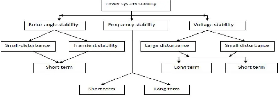
1.1 Classification of Power System Stability: Power System Stability is categorised [1] in to three types: (i) Rotor Angle Stability (ii) Frequency Stability (iii) Voltage Stability
1.2 Rotor Angle Stability: The ability of a synchronous generator to retain the state of synchronism in a power system when subjected to disturbances is said to be the rotor angle stability. It is dependent on the capacity of machine to maintain the equilibrium state in between electro-magnetic torque and mechanical torque of each synchronous machine in the system. This type of instability occurs in the form of swings of the generator- rotor which leads to loss of synchronism.
1.3 Small Signal Stability: The capacity of power system to retain the synchronism state when subjected under small disturbances is known as small signal stability [2]. If the equations which describe the resulting response of the system may be linearized for the purpose of analysis then a disturbance is supposed to be small. Instability may be of two forms (i) Scarcity of synchronizing torque which leads to steady increase in generator-rotor angle. (ii) Lack of adequate torque due to which rotor oscillations with increasing amplitude are generated. At present time, the problem of small signal stability occur due to inadequate damping of oscillations.
stability. In these conditions, the linearized power system model does not generally apply and the non-linear equations must be used directly for the purpose of analysis.
Figure 1: Classification of Power System Stability
1.5 Dynamic Stability: This type of stability is generally used to determine the separate class of stability.
Paper is organized as follows. Section II describes automatic text detection using morphological operations, connected component analysis and set of selection or rejection criteria. The flow diagram represents the step of the algorithm. After detection of text, how text region is filled using an Inpainting technique that is given in Section III. Section IV presents experimental results showing results of images tested. Finally, Section V presents conclusion.
II. BACKGROUND
The variations in the value of voltage above and below some mean value in an alternating current is called as Oscillation. These oscillations cause instability in a power system. And if they do not damped effectively, they may cause the breaking of entire power system.
2.1 Types of Oscillations: Oscillations in a power system are classified by the components of the system that they affect. Some of the major kinds of power oscillations are [3] mentioned as: (i) Intraplant mode oscillations (ii) Local plant mode oscillations (iii) Inter area mode oscillations (iv) Control mode oscillations (v) Torsional mode between rotating plant.
2.1.1 Intra plant mode oscillations: The oscillations in which machines oscillate against each other on the same generation site from 2 Hz to 3 Hz are known as Intra plant oscillation. This is because the oscillations retain themselves within the generation plant complex. The rest of the system is remain uninfluenced.
2.1.2 Local plant mode oscillations: The local mode involves swinging of one generator against rest of the system from 1 Hz to 2 Hz. The variation in speed of generator is shown in figure 2. The influence of oscillation is confined to the generator and the line connected to the grid. The rest of the system is treated as a constant voltage source and its frequency is supposed to be constant. This is known as Single-Machine-Infinite-Bus (SMIB) model. The removal of oscillation may be executed by a single or dual input PSS. They provide modulation of the voltage reference of the Automatic Voltage Regulator (AVR) with proper phase and gain compensation circuit.
2.1.3 Inter-Area mode oscillations: Inter-Area Oscillations are dominant over a major portion of network. It includes two coherent groups of generators that are swinging against each other at 1.0 Hz or less. The change in tie line power may be large which is shown in figure 3.
associated controls determine the damping features of the inter-area mode. The operation of the system in the presence of a lightly damped inter-area mode is very difficult.
Figure: 2 Waveform of Local Mode Oscillation
Figure 3: Inter-Area Mode Oscillations Graph
III.POWERSYSTEMSTABILIZERS
The elementary principle of a power system stabilizer (PSS) is to provide damping to the oscillations of generator-rotor by controlling its excitation with the help of auxiliary stabilizing signal(s). The stabilizer must produce a component of electrical torque in phase with the rotor speed deviations in order to provide sufficient damping.
Synchronous electric power generators are used to produce alternating current output voltages, namely single phase or three phase voltage outputs. A synchronous electric power generator consists of a stator and a rotor that has a field winding excited by a field voltage provided by an exciter. Current in the rotor creates a rotating magnetic field which induces current in the stator to produce an output voltage at the terminals of the stator. The amount of field voltage provided by the exciter controls the generator field magnetic strength. As the main generator field strength is controlled, so is the generator output voltage induced in the generator stator.
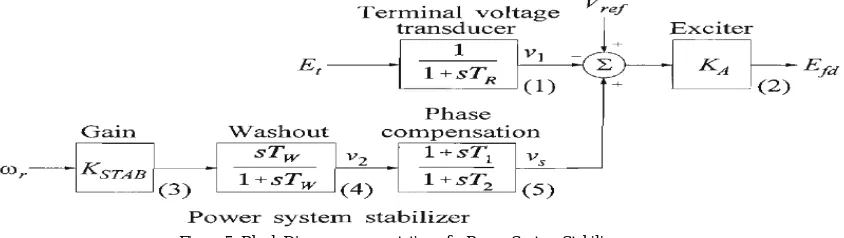
Figure 4: Block Diagram representation of Power System with Stabilizer
to acquire the required phase compensation. The frequency range of interest is from 0.1 to 2.0 Hz, and the phase lead network should provide compensation over this entire frequency range. The signal washout block acts like a high-pass filter, having time constant TW. It allows the signals which are associated with oscillations ωr to pass without any
variation. In its absence, steady changes in speed would change the terminal voltage. It allows the PSS to respond towards the variations in speed. The magnitude of Tw lies in the range of 1 to 20 seconds. The stabilizer gain KSTAB is
employed todetermine the amount of damping provided by the PSS. Ideally, the gain should be set at a value corresponding to maximum damping; but, it is often limited by the other considerations. When a PSS is employed, care should be taken that the overall system stability should be enhanced, not only the small signal stability.
The conventional power system stabilizers [5] apply the local signals like rotor speed or frequency, active power for input signals in order to add damping torque in phase with the speed deviation to damp local and inter-area oscillations. The PSSs are good source of damping for local oscillations and for inter-area oscillations upto certain extent if PSSs parameters are designed for wide-range of operating conditions. But the PSSs along with other local controllers are unable to ensure all the time stability of the power system if they are subjected to severe disturbances because of the non-linear and multi-variable nature of power system. Due to the deregulation of the power system, the transmission and receiving of bulk power in between the mutually connected region over long distances causes an increase in the inter-area oscillations that cannot be effectively damped by the employment of local PSSs. The inter-area oscillations can have significant influence on power system rather than local oscillations. To know about the nature of inter-area oscillations, the whole interconnected power system has to be represented in details as the inter-area oscillations are due to the dynamic interactions of the weakly coupled network; whereas, local oscillations are limited to their local regions only. Here are the following two design methods used to develop supervisory PSSs to effectively damp inter-area oscillations.
Figure 5: Block Diagram representation of a Power System Stabilizer
help of local generator rotor speed as input signal. The compensation angle is calculated at the local mode frequency, and the controller time constants are chosen accordingly. Therefore, the local mode will be very highly damped. This part of the controller is called PSS l. It is treated as a first-level controller [6] in a two-level control scheme. The figure of this design is shown below. Let the second control signal is ug, which is used to provide damping for the inter-area oscillations, and it is controlled from the selected machines with the help of global input signal. The angle of compensation is calculated at the inter-area mode frequency by using a global input signal with PSS l in service, and the controller time constants are selected to bring this angle. This part of the controller is called as PSS 2. It acts as a second-level controller or the coordinator as shown in Figure 6.The main function of this controller is to achieve the measurements of global signals and send a control signal in terms of these measurements to the selected machines for controlling the inter-area oscillations. Therefore, the total control signal for the jth machine is written as
u
j = ujl + ujgFigure 6: Proposed two-level PSS design
3.2 H ∞ Based Damping Controller Design: Another controller design [7] which handles the stability of large power system with a wide range of operating conditions is the design of H∞ damping controller. The first step for studying this design is to execute the analysis of modal to obtain the measurements in concern with frequency, damping ratio and mode shape. This is beneficial to obtain the identification of group of generators which often oscillate against other group of generators, leading to inter-area oscillations. The H∞ problem is to alleviate the effects of the disturbance on the output of the plant such that
Max│ S(jω) │ │W1-1(jω) │ (1)
where S (jω) is called as closed-loop transfer function from disturbance to the plant output, and W1-1(jω) is the
acceptable magnitude of error in the presence of disturbances. To accommodate for the nominal plant's additive and multicaptive uncertainties, ΔA(s) and ΔM(s) respectively, in the H∞ problem, the following equations yield:
Max │R( j)│ │ΔA( jω) ││W2-1(jω) │
Max │ T( j) │ │ΔM ( j)│= │W2-1(jω) │, for all ω (2)
where R(jω) and T(jω) are the transfer functions of the perturbed plant with controller shown in [7]. An optimal controller is obtained from the H∞ algorithm whose performance must meet the following equations together:
││W1(jω )S (jω ) ││
││W2(jω )R (jω ) ││ 1 (3) ││W3(jω )T (jω ) ││
two Riccati equations are solved. The details of the solution can be found in the literature [8, 9]. The optimal parameters of controller are significantly influenced by the weighting functions, W. Since long time delays if not taken into consideration will result in phase lag with respect to frequency of oscillatory mode instead of compensating for the phase lag and could also result in gain amplification with respect of oscillatory mode damping. Therefore, it is necessary to shift the eigenvalues of the oscillatory modes to undesirable places on the complex plane, which leads to the destabilizing of power system instead of stabilizing [10]. The next proposed H∞ based SPSS includes delayed-input wide area measurements by using Gain Scheduling Method. The linear matrix inequality (LMI) H∞ method is used to design the SPSS. Local generators ensure the measurement of their speed deviations and used in the form of inputs to the SPSS. System plant is expressed by the equations:
ẋ = A(q)x + B1(q)w + B2u
z = C1(q) x + D11 (q)w + D12 u (4)
y = C2 x + D21w + D22u
To design H∞ parameter-dependent controller using GS method, the controller must be expressed as
ẋk = Ak (q)x + Bk(q)u
(5) yk = CK (q)x + Dk (q)u
where the values of Ak(q), Bk(q), Ck(q),and Dk(q) can be determined as
Ak (q) Bk(q) Akqi Bkqi
(6) i=1niC kqi D kqi
CK (q) Dk (q)
where α is
q = iqi (7)
The controller state-space can be determined by the convex interpolation of the LTI vertex controllers at the operating point q:
(Akqi Bkqi)
(8) (Ckqi Dkqi)
Consequently, a robust, smooth switching controller is obtained by the parameter measurements q which can be an index of operating conditions or a signal of interest. This method can be applied to form a stabilizing controller for system with time delay as shown in Figure 7. If the time delay is approximated by first order Pade approximation, it can be expressed as,
ẋ = - 2 x/ τd + 4 u/ τd (9)
y = x – y
If 1/τd is replaced by q, then
Ad(q) = -2q Bd(q) = 4q
(10)
Cd(q)=1 Dd(q) = -1
When the system plant model and the time delay model are connected, the LMI H∞ controller design can be applied to the delayed-input system plant for obtaining robust, linear time-invariant for each operating condition, and the controller's parameters are measured in real time as previously stated. It should be kept in mind that the local PSSs are removed from the study model when the SPSS is tested.
Figure 8: SPSS Controller
IV.CONCLUSION
The brief description of the Power System Stability along with its classification and about the oscillations is provided. The analysis is also executed on the various types of oscillations with their nature of variation with time and shown in the graphical format. The Power System Stabilizer is also discussed and it is also explained that what is the requirement of supervisory PSSs in place of conventional PSSs. The two methods of supervisory PSSs have been successfully explained and it is observed that these supervisory PSSs are much more efficient than conventional PSSs due to their sufficient ability of damping local as well as inter-area oscillations.
REFERENCES
[1] A.K. Swagat Ranjan, Ashit Kumar, Abhinash Mohapatra, “Design Of Power System Stabilizer”, National Institute of Technology, Rourkela, 2012.
[2] P. Kundur, “Power System Stability And Control”, Mcgraw-Hill, 2007. [3] Pal B., Chaudhury B. “Robust Control in Power Systems”, Springer, 2005.
[4] L.L. Grigsby, “The Electric Power Engineering Handbook”, IEEE Press And CRC Press, 2001.
[5] H. Behbehani, Z. Lubosny and J.W. Bialek “Survey of Supervisory Power System Stabilizers For Enhancement of Power System Stability” Universities Power Engineering Conference, IEEE Publications Conference, 2007 (DOI:10.1109/UPEC.2007.4468985).
[6] Aboul Ela, M.E., A.A. Sallam, J.D. McCalley, and A.A. Fouad "Damping controller design for power system oscillations using global signals," IEEE Transactions on Power Systems, vol. 11, pp. 767, 1996.
[7] M. Klein, L.X. Le, G.J. Rogers, S. Farrokhpay, N.J. Balu “H∞ Damping Controller Design in Large Power Systems” IEEE Transactions on
Power Systems, Vol. 10, No.1, February 1995.
[8] MathWorks, "Robust-Control Toolbox,MATLAB User's Guide," 1981.
[9] Francis, B. A., "A Course in H∞ Control Theory, Lecture Notes in Control and Information Sciences," 1987.