Design and Analysis of Jig Fixture for Radial
Drilling Machine
Harsh B. Mewada1, Rakibkhan S. Bahelim2, Hiren H. Dave3, Sanjay B. Patel4, Chirag S. Jivrajani5,
Jitendra H.Rathod6
UG Student, Dept. of Mechanical Engg. , Indrashil Institute of Science & Technology, Rajpur, Kadi, India1 2 3 4 Asst. Professor, Dept. of Mechanical Engg. , Indrashil Institute of Science & Technology, Rajpur, Kadi, India5
Design Engineer, Ahmedabad, India6
ABSTRACT: Nowadays development is most important to step ahead for any organization. For that every organization has started using technology and all the possible action to step forward their production and sustain in market. To increase the production, industry decreases the production time. To decrease the production time everyone is developing new mechanism and automation. For drilling machine to reduce the production time jig and fixtures are used. This paper indicates the design and analysis of jig fixture for the drilling machine, where jig fixture is used to cut the work piece from four directions. The structural analysis has been carried out in ANSYS 16.0 whose result helps to examine the design.
KEYWORDS: Jig Fixtures, Increase Production, Drilling Machine and Radial Drilling Machine.
I. INTRODUCTION
be accomplishing our Objective. Jigs are identified by their basic construction. The two common forms of jigs are open and closed jigs. Open jigs carry out operations on only one, or sometimes two, sides of a work piece. Closed jigs, on the other hand, operate on two or more sides. The most-common open jigs are template jigs, plate jigs, table jigs, sandwich jigs, and angle plate jigs. Typical examples of closed jigs include box jigs, channel jigs, and leaf jigs.
II. LITERATURE REVIEW
NBV Lakshmi kumari and G prsasanna Kumar said in [1], the basic elements in the design of indexing type of drill jig is the component model, location, orientation and clamping. The scope of this paper is to design an indexing type of drill jig for a component having angular holes at 25 deg such the design is validated and verified. The present paper entitled “Design and Analysis of Indexing type of Drill Jig” is the work done for the design and analysis of Jig. Jigs are mainly used for mass production and for interchangeable parts concept, for a long period in the manufacturing of Jigs. This type of jig is used to drill a series of holes in circle on the face of work piece. For indexing, the mechanism adopted is spring and plunger arrangement. When the handle is pulled down the spring disengages and the locator with bracket is rotated such the next position of the hole is pointed by the taper bush and the pin sits in the exact position of the hole, in that way the indexing is achieved. This is the common methods of indexing which can be operated easily and here the operating type is also reduced. As per paper clamping force is more than drilling force hence we can say that design is safe for machining.
Marian Funaru said that in [2], presents a new technical solution of the rotary table indexing mechanism used on milling machining centers, which offers a very high positioning precision, by using a curvy coupling and a hydraulically driven table clamp/unclamp mechanism. Nowadays the performance requirement of mechanical manufacturing is characterized by the constantly increasing demand of machine tools positioning precision. The challenge also consist the precise tooling operation at reasonable costs. In order to meet the challenge it is necessary to reduce the process time. The machining centers give the advantage of increased the productivity, due to the reduced auxiliary time , through concentrating a higher number of operations needed for changing the work piece position and avoiding the removal, transport, setting and alignment of the work piece, which in many cases represents the source of many errors. Another main advantage is eliminating the errors caused by the human while setting the work piece. In this paper, a precise rotary table indexing and clamping/unclamping system was presented, which plays a very important role in obtaining a high manufacturing precision of the machining centre. The indexing mechanism of the rotary table offers a high positioning precision and also a high repeatability, by making use of a precise curvy coupling in the mechanism’s structure, which has a minimum indexing angle of one degree. Also, the gears and the pinion shaft used in the transmission system are manufactured in a high accuracy class. In this paper the technical solution is significantly reduced the auxiliary time of the manufacturing process and also the errors caused by the setting of work piece.
III. MATHEMATICAL CALCULATION
The mathematical calculation of the shaft design, journal bearing and structure are calculated according to the load on the drilling machine.
3.1 Shaft Design
The shafts may be design on the basis of strength, rigidity and stiffness. For the calculations formulas are referred from [4].
In designing the shaft on the strength of basis, we will consider the following cases: (a) Shafts subjected to twisting moment or torque only,
(b) Shafts subjected to bending moment only,
(c) Shafts subjected to combined twisting and bending moments,
(d) Shafts subjected to axial loads in addition to combined tensional and bending loads.
In this design we will consider only shaft subjected to bending moment only. Shafts Subjected to Bending Moment Only: When the shaft is subjected to a bending moment only, then the maximum stress (tensile or compressive) is given by the bending equation.
We know that M / I = Ϭb/ y... (1) Where
M = Bending moment,
I = Moment of inertia of cross-sectional area of the shaft about the axis of rotation, σb = Bending stress, and
y = Distance from neutral axis to the outer-most fiber. We know that for a round solid shaft, moment of inertia, I = ( π / 64 ) * (d)4 and y = d/2
Substituting these values in equation (i), we have
M =( π / 32 ) * Ϭb * (d)3
From this equation, diameter of the solid shaft (d) may be obtained.
Here the Shaft length: 900 mm, Load W : 300 kg on each end, Bending stress (Ϭb) : 850 N/mm2, Shaft diameter = d (unknown). Thus, here 300kg load is apply on each end, so 300*10 = 3000 N
Now maximum bending moment (M) on shaft is, as shown in fig.1
Fig.1 Free Body Diagram of shaft
M = ( 3000*200) + (3000*700) + (3000*200) + (3000*700) M = 54 * 105 N.mm
D = 40.143 mm.
3.2 Journal Bearing
The following procedure may be take in designing the journal bearing, when the bearing load, diameter, and the speed of the shaft are known. The formulas for calculation is carried out from [6]
Here, Shaft diameter - d= 41mm as calculated above, max load W= 6000 N, N = 2r.p.m
let, Power (P) :-L/d = 1.2, So, approx we have taken 50 mm.
Power (P) = W/ld, Now, Z= viscosity,
l = 1.2 * d Co-efficient of Friction
P = 6000/50*41 ZN/P = 0.06 *2 /2.97 = 0.04,
l = 1.2*41 3k = ZN/P,
P = 2.97 N/mm2 k = 1/3(ZN/P), l = 49.2 mm K = 0.013,
µ= 33/108 (ZN/P) (d/C) + K, µ = 33/108 (0.04) (1/0.001) + 0.02 µ = 2.0132 * 10-3
µ = 0.0020132
3.3 Structure calculation
For the structure calculations the formulas are referred from [5].
From the above Figure 2 we can say that, Ra + Rb = 1200 N, equation ( 2 )
And,
Fig.2 Free Body Diagram of Load Acting on Structure
AC = ( 250 / cos15) AC = 259 mm
Now, AG + CG = AC CG =68 mm
Now take moment @ A;
(600*68) + (600*568) = (Rb*636)
Rb = 600 N
From equation no ( 2 ) we have, Ra = 600 N
IV. MESHING
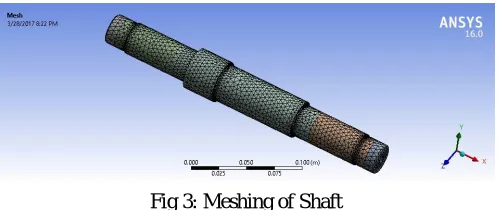
We have done meshing of the shaft in ANSYS mechanical module. In this we have selected Mechanical as physical preference and advanced size function is selected on curvature. On the basis of this parameters shaft is discredited in 63265 nos. of nodes and 40591 nos. of elements.
Fig 3: Meshing of Shaft
Fig 4: Meshing of Structure
V. RESULTS
For checking the safety of the shaft for normal operation we have done analysis in Ansys modal module. In this we have applied the 300 Kg Load on both ends of the shaft and we have also defined fix supports and bearings.
After the analysis is completed we have obtain the result as shown in fig 5. From the figure we can see that Maximum Principle stress developed in the shaft geometry is 340 Mpa.
Fig 5: Result of Shaft
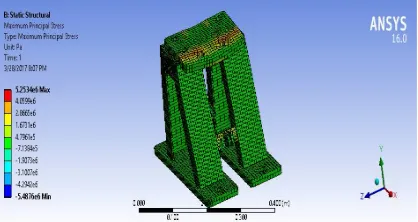
For checking the safety of the Structure 3D Modal for normal operation we have done analysis in Ansys static structural module. In this we have applied the 600 Kgs of Load on jig plate of the structure and we have defined 2 fix supports at the bottom of the structure. After the analysis is completed we have obtain the result as shown in fig 5. From the figure we can see that Maximum Principle stress developed in the shaft geometry is 5.25 Mpa
VI. CONCLUSION
According to the load on drilling machine, calculation of shaft, bearing and structure has been carried out. The result of structural analysis of shaft and structure shows that around 300MPa and 5.25MPa respectively maximum principle stress is evolved. This signifies that the design is safe
REFERENCES
[1] NBV L. Kumari and G.P. Kumar, “Design and Analysis of Indexing Type Jig Drill”, IOSR journal of mechanical and civil engineering, vol. 12, iss no. 2, pp- 46-51, April 2015.
[2] M.Funaru, G. Stan, L. Mihaila, M.Pascu,D. Andrioaia, “Precise Rotary Table Indexing System Used on Milling Machining Centers”, Journal of Engineering Studies and Research, vol. 19, iss no. 1, 2013.
[3] A. Mourya, C.Patil, P. Chavan,M.Sande, S.Pisal, “Automatic Indexing Mechanism for Drilling Machine”, ICETTSURC0S, pp-413-479, April 2015
[4] R.S. Khurmi and J.K. Gupta, “Shaft,” in The Textbook of Machine Design ,1st color ed. Eurosia Publisher Pvt. Ltd., 2015
[5] R.S. Khurmi and J.K. Gupta, “Sliding Contact Bearing,” in The Textbook of Machine Design ,Ist color ed. Eurosia Publisher Pvt. Ltd., 2015 [6] C. Y. Lin, M. Wu, J. A. Bloom, I. J. Cox, and M. Miller, “Rotation, scale, and translation resilient public watermarking for images,” IEEE