Design and Analysis of an Internal
Combustion Engine Piston Head to Increase
the Torque on Crankshaft
Nagasundaram.S1, Nester Ruban.J2
M.E. CAD/CAM Engineering, Department of Mechanical Engineering, JJ College of Engineering and Technology, Tiruchirappalli, Tamil Nadu, India1
Assistant Professor, Department of Mechanical Engineering, JJ College of Engineering and Technology, Tiruchirappalli, Tamil Nadu, India2
ABSTRACT: The in-cylinder air motion in internal combustion engines is one of the most important factors controlling the combustion process combustion efficiency of CI engine and emissions especially NOx can be controlled by creating turbulence, by designing intake system, by designing combustion chamber. A good swirl promotes fast combustion to improve the efficiency. So in the present work a study about the influence of air swirl in the combustion chamber upon the performance and emission of a diesel engine is studied. The intensification of the swirl is studied on the crown of the piston by three different configurations of Models are, Mitsubishi, Pan and Shallow Hasselman. CFD analysis is carried out on a diesel engine using different configuration pistons which is four stroke engine cylinder air cooled and constant speed. Performance parameters such as turbulent kinetic energy and turbulent intensity and turbulent dissipation are calculated. CREO is parametric used for design and Ansys IC Engine Solver 15.0 is used for analysis.
KEYWORDS: IC Engine, Piston Head, Air Swirl, Turbulent, CREO, Ansys 15.0 IC Engine Solver.
I.INTRODUCTION
Internal combustion engines have been relatively inexpensive and reliable source of power for application ranging from domestic use to large scale industrial and transportation applications for most of the twentieth century. DI Diesel engines, having the evident benefit of the higher thermal efficiency than all other engines, have served for both Light-Duty and Heavy-Light-Duty Vehicles.
The in-cylinder fluid motion in the internal combustion engines is one of the most important factors controlling the combustion process. It governs the fluid-air mixing and burning rates in Diesel engines. The fluid flow prior to combustion in internal combustion engines is generated during the induction process and development during the compression stroke (Xuelinag and shusong, 1990; and shaoxi and Wanhua, 1990).Therefore, a better understanding of fluid motion during the induction process is critical for developing engine designs with the most desirable operating and emission characteristics (Wu zhijun and Huang Zhen, 2007).
Swirl interaction (Ogawa et al, 1996) with compressed induced squish flow increases turbulence level in the combustion bowl, promoting mixing. Since the flow in the combustion chamber develops from interaction of the intake flow with the in-cylinder geometry, the goal of this work is to characterize the role of combustion chamber geometry in-cylinder flow, thus the fuel-air mixing, combustion and pollutant formation processes. It is evident that his effect of geometry has a negligible effect on the airflow during the intake stroke and early part of the compression stroke. But the piston moves towards Top Dead center (TDC), the bowl geometry has a significant effect on airflow thereby resulting in better atomization, better mixing and better combustion. The re-entrant chamber without central projection with sharp edges provides higher swirl number than all other chambers (Gunabalan and Ramaprabhu, 2009).
II. INFLUENCE OF AIR MOTION IN COMBUSTION CHAMBER
To enhance the efficiency of the engine it is important to optimize thermal efficiency, which is obtained at highest possible compression ratio. However, if the compression ratio is too high, there is a chance to have knock, which should be avoided at all cost. A solution for the problem is to promote rapid combustion, to reduce the time available for the self-ignition to occur (Jorge martin’s et al., 2009). To promote rapid combustion, sufficient large-scale turbulence (Kinetic Energy) is needed at the end of the compression stroke because it will result in a better mixing process of air and fuel it will also enhance flame development.
However, too much turbulence leads to excessive heat transfer from the gases to the cylinder walls, and may create problem on flame propagation (Stone, 1989; Blair, 1999; and Lumley, 2001). The key to efficient combustion is to have enough swirl in the combustion chamber prior to ignition. In order provide complete combustion at a constant rate, there is common design objective of bringing sufficient sir in contact with the injected fuel particles. For this purpose, the piston crown and the cylinder head are shaped to induce the swirling motion to air while moving compression piston is moving towards TDC.
The production of Turbulence, i.e., swirl by different means, however, is considered necessary for better fuel-air mixing. The complexities of productions and higher cost of this methods of creating turbulence of the limiting factors in their wider use. An increase in air swirl level is noted to increase the air mass of all zones. Thus at the moment when the mixture first ignites in one zone, all other zones approaching their self-ignition temperature contain more air. Increased swirl results in an increase in initial combustion rate and hence higher rate of pressure rise is expected (Payriet al, 1990).
III. ENGINE EFFICIENCY
Once ignited and burnt, the combustion products—hot gases—have more available thermal energy than the original compressed fuel-air mixture (which had higher chemical energy). The available energy is manifested as high temperature and pressure that can be translated into work by the engine. In a reciprocating engine, the high pressure Gases inside the cylinders drive the engine’s pistons.
Once the available energy has been removed, the remaining host gases are vented (often by opening a valve or exposing the exhaust outlet) and this allows the piston in to the previous position (top Dead center, or TDC).This piston can then proceed to the next phase of its cycle, which varies between engines. Any heat that is not translated in to work is normally considered a waste product and is removed from the engine either by an air or liquid cooling system.
Internal combustion engines are primarily heat engines, and as such their theoretical efficiency is calculated by idealized thermodynamic
Cycles. The efficiency of the theoretical cycle cannot exceed that of the Carnot cycle, whose efficiency is determined by the difference between the lower and upper operating temperatures of the engine. The upper operating of the terrestrial engine is limited by the thermal stability of the materials used to construct it. All metal and alloys are eventually melt or decompose, and there is significant researching into ceramic materials that can be made with greater thermal stability and desirable structural properties. Higher thermal stability allows for greater temperature difference between lower and upper operating temperatures, hence greater thermodynamic efficiency.
The thermodynamic limits assume that the engine is operating under ideal conditions: a frictionless worlds, ideal gases, perfect insulators, and operations for infinite times. Real world applications introduce complexities that reduce efficiency. For example, a real engine runs best at a specific load, termed its power band.
The engine in a car cruising on a highway is usually operating significantly below its ideal load, because it is designed for higher loads required for rapid acceleration. In addition, factors such as wind reduce overall system efficiency. Engines fuel economy is measured in miles per gallon or in liters per 100 kilometers. The volume of hydrocarbon assumes a standard energy content.
Most steel engines having a thermodynamic limit of 37%. Even when aided with turbochargers and stock efficiency aids, most engines retain an average energy of about18%-20%.
Rocket engine efficiency are much better, at 70%, because they operates at very high temperatures and pressures and can have very high expensive ratios. Electric motors are better still, at around 85-90% efficiency or more, but hey rely on an external power source (often another heat engine at a power plant subject to similar thermodynamic efficiency limits).
There are many inventions aimed at the increase the efficiency of IC engines. In general, practice engines are always compromised by trade-offs between different properties such as efficiency, weight, power, heat, response, exhaust, emissions, or noise. Sometimes economy plays a role in not only the cost of manufacturing and engine itself, but also manufacturing and distributing the fuel. Increasing the engine’s efficiency brings better fuel economy but only if the fuel cost per energy content is the same.
IV. COMBUSTION SECTOR METHOD IN ANSYS CFD SOFTWARE
(i) (ii) (iii)
Fig 1: Types of piston Types of piston
i. Pan ii. Mitsubishi
iii. Shallow Hasselman
Fig 2: Sector Method geometry for model AVL (TDC to BDC)
Specification of the engine used for analysis in Ansys IC Engine Solver
Analysis type= ICE (Sector type combustion method) Engine Type = Diesel Engine
Crank Radius = 40 Minimum Lift = 0.2 IVC = 570
EVO = 833
Minimum Spray Length = 0.02 Spray Angle = 70 degree Combustion Mixture O2 = 0.232
CO2 = 0.00046
H2O = 5e-7
Total flow rate = 0.10 Kg/sec
Other specification are default value in IC Engine Solver. We can change them as per our convenience of Analysis
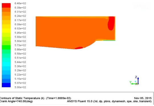
Fig 3: CFD result for model Mitsubishi at CA 740 Fig 4: CFD Result for model Pan at CA 740
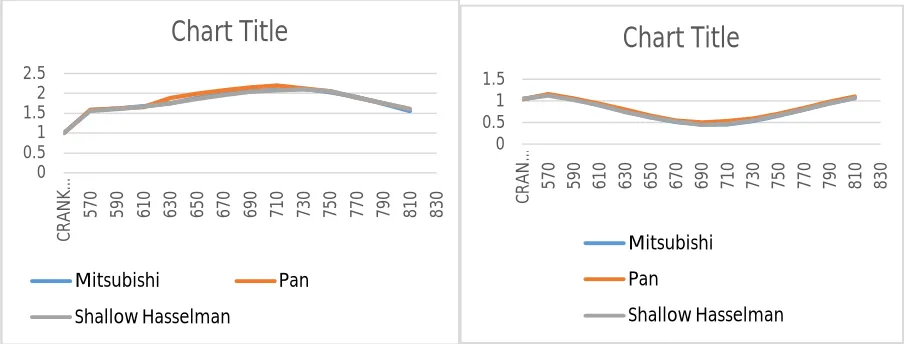
Fig 9: Turbulent kinetic Energy Fig 10: Turbulent intensity
Fig 11: Turbulent dissipation Result
V. RESULT
The results for the modified pistons are taken from the Computational Fluid Dynamics Analysis. The calculated swirl ratio is 1.3. The results are taken and compare between 6 pistons to get the better modified model. Combustion sector method is done at IC Engine Solver Ansys Software. From the CFD Result we can assure that the model Pani is Efficient than other 2 models. The turbulence is increased compared to other models results better burning of fuel during the combustion operation in IC Engine Piston. Normally Fuel burning ratio is between 70 to 80 percentages. The higher ratio gives us the good fuel burning efficiency.
Due to the burning efficiency there is high combustion rate in the internal combustion engine. When the combustion is increased the speed of the piston stroke is increased which results in increase of torque on Crank Shaft.
0 0.5 1 1.5 2 2.5 C R AN K … 5
70 590 610 630 650 670 690 710 730 750 770 790 810 830
Chart Title
Mitsubishi Pan Shallow Hasselman 0 0.5 1 1.5 C R AN … 570 590 610 630 650 670 690 710 730 750 770 790 810 830
Chart Title
Mitsubishi Pan Shallow Hasselman 0 500 1000 1500 C R AN K AN GL E 5 7 0 5 9 0 6 1 0 6 3 0 6 5 0 6 7 0 6 9 0 7 1 0 7 3 0 7 5 0 7 7 0 7 9 0 8 1 0 8 3 0Chart Title
So the modified model Pan is consider as good and efficient model but the solution also want to analysis the model practically to justify. In this paper, CFD based experiments are concentrated.
REFERENCES
[1] Dr.S.L.V. Prasad, Prof V.Pandurangadu, Dr.P.Manoj Kumar, Dr G. Naga Malleshwara Rao (Enhancement Of Air Swirl In A Diesel Engine With Grooved Cylinder Head)
[2] SanthoshKumar.G,Prof.K.Hema Chandra Reddy , Ch.Rajesh, G.Suresh Kumar(A Review On Study Of The Effect Of In Cylinder Air Swirl On Diesel Engine Performance And Emission)
[3] R. C. Singh, Roop. Lal, Ranganath M S, Rajiv Chaudhary(A Review : Failure Of Piston In Ic Engine)
[4] B.Madhubabu, Prof. K. Govindarajulu And Dr.S.L.V.Prasad (Experimental Investigation Of A Single Cylinder 4- Stroke Di Diesel Engine By Swirl Induction With Two Different Configuration Pistons)
[5] Vaibhav Bhatt, VandanaGajjar (Experimental Investigation Of Performance And Exhaust Emission Characteristics Of Diesel Engine By Changing Piston Geometry )