CANNING, ELECTRICAL RESISTANCE AND SCRAPED SURFACE HEAT EXCHANGER ASEPTIC PROCESSING, OF FOOD PRODUCTS WITH LARGE PARTICLES
by
JOSE FRANCISCO PASTRANA-ZUNIGA
A thesis submitted to the Graduate Faculty of North Carolina State University
in partial fulfillment of the requirements for the Degree of
Doctor of Philosophy
BIOMATHEMATICS GRADUATE PROGRAM DEPARTMENT OF STATISTICS
Raleigh 1992
APPROVED BY:
Dr. Ronald E. Stinner
-PASTRANA-ZUNIGA, JOSE FRANCISCO. A Model for the Heat Transfer Processes that Occur During Canning, Electrical Resistance and Scraped Surface Heat Exchanger Aseptic Processing, of Food Products with Large Particles. (Under the direction of Dr. Harvey J. Gold, and Dr. Kenneth R. Swartzel.)
A unified model for the heat transfer processes that take place within a food product, thermally treated by alternative processing system types (PST's), is developed and computationally specified. The different PST's considered are: canning, electrical resistance (ER) and scraped surface heat exchanger (SSHE) aseptic processing. The basic food product considered is lean beef in gravy, under product formulations (PF) that differ according to~the gravy: without starch; with 3% starch, where the gravy electrical conductivity is greater than that of the beef; with less than 3% starch, where the gravy electrical conductivity is equal to that of the beef.
Two modelin"g principles" were applied in establishing the unified model: system segregation, and thermodynamic energy balancing. The system, defined as the product being subjected to one of three stages, heating (H), thermoequilibrium (THEQ), or cooling (C) stage, is first segregated into fluid (gravy) and solid (beef cubes), and next, the beef cubes are identically segregated into regions, and each region within a beef cube, is considered to be a thermodynamic subsystem. Energy balances are established for the fluid, and each region in just an octant of a beef cube (heat transfer symmetry consideration), to arrive to a system of ordinary differential equations (ODE's).
chemical food quality by computing variables such as: point or integrated spore, enzyme, and nutrient equivalent thermal destruction times, and spore, enzyme, and nutrient percent concentration.
DEDICATION
There are two women that I can not ignore as I conclude the present work: My mother MARIA JOSEFA ZUNIGA O. who helped me, to the point of sacrifice, to initiate and continue studies beyond elementary school, and my wife MIRIAM GALLARDO DE PASTRANA who has supported me, also to the point of sacrifice, during my studies beyond high school.
BIOGRAPHY
Jose Francisco Pastrana-Zuniga was born in San Jose, Costa Rica on April 2, 1944. He was educated in costarican public schools, and in December 1963, he graduated the Liceo de Costa Rica high School.
He entered the University of Costa Rica (UCR), and received a teaching degree in math in August 1973, and a Bachelor degree in Statistics in August 1974. While completing the Licenciatura degree in Statistics, he worked as an assistant professor from 1974 to 1975, teaching undergraduate courses in the School of Statistics, UCR. In June 1975 he came to the United States, after the UCR awarded him a scholarship to undertake graduate studies in the University of Wisconsin-Madison (UW-Madison). From August 1975 to August 1979 he was a full time graduate student in the UW-Madison, Department of Statistics, carrying studies of Statistics applied to two areas: Industry (Regression Analysis, Experimental Designs in Industry, Response Surface Methodology and Time Series Analysis), and Business (Optimal Statistical Decisions, Managerial Economics, Applied Multivariate Analysis, Time Series Analysis). In August 1979, he received an M. Sc. degree in Business-Statistics.
From 1979 to 1987 he worked as an associate professor in the School of Statistics, UCR, and as consultant to some government institutions (banks, planning office, etc.). During this period, he contributed to organize and enhance the School of Statistics consulting service, and he was chairman ad interim of the School for more than a year.
ACKNOWLEDGEMENTS
I gratefully acknowledge the efficient work of the Advisory Committee, and express thanks to each of its members: to DR. HARVEY J. GOLD, chairman of the Committee, for his skillful guidance, and sincere friendship throughout the research project development; to DR. KENNETH R. SWARTZEL, Director of the Center for Aseptic Processing and Packaging (CAPPS), for sheltering the research project within CAPPS's umbrella, and for the his encouragement, support and friendship along the project development; to DR. RONALD STINNER, former Director of the Biomathematics Graduate Program, for his valuable advice when I was just establishing my Plan of Graduate Work, and the helpful comments he expressed during several discussions on the research topic; to DR. H. ROBERT VAN DER VAART, for his availability whenever I needed to meet with him to discuss thesis related topics, and for the helpful insights he expressed during the meetings; to DR. KENNETH W. HANCK, Graduate School representative, for the endurance shown during the long oral preliminary, and final oral examinations.
TABLE OF CONTENTS
LIST OF TABLES viii
LIST OF FIGURES ix
LIST OF SYMBOLS xv
SyMBOLS xv
SUBSCRIPTS xvii
SUPERSCRIPTS xviii
G REEK LETTERS xix
ABBREVIATIONS xix
INTRODUCTION 1
MANUSCRIPT I UNIFIED MODEL FOR THE HEAT TRANSFER PROCESSES THAT OCCUR DURING CANNING, SSHE AND ELECTRICAL RESISTANCE ASEPTIC
PROCESSING OF FOOD PRODUCTS THAT CONTAIN LARGE PARTICLES 4
ABSTRACT 5
INTRODUCTION 5
THEORY 9
ILLUSTRATION 33
NOMENCLATURE 52
REFERENCES 58
MANUSCRIPT II COMPUTERIZED SPECIFICATION OF A UNIFIED MODEL FOR THE HEAT HEAT TRANSFER PROCESSES THAT OCCUR DURING CANNING, SSHE ANDELECTRICAL RESISTANCE ASEPTIC PROCESSING OF FOOD PRODUCTS WITH
LARGE PARTICLES 64
ABSTRACT 65
INTRODUCTION 65
COMPUTERIZED MODEL DESCRIPTION 71
RESULTS 76
INTRODUCTION 76
APPLICATIONS IN DESIGN MODE 77
APPLICATIONS IN EVALUATION MODE 82
NOMENCLATURE 114
LIST OF TABLES
MANUSCRIPT II
LIST OF FIGURES
MANUSCRIPT I
FIG. 1: Flowchart of the general system . . . • • . . . • . . • . • . . • • . . • . . . 10
FIG. 2: Heat transfer during canning and SSHE H stage ••.••.•.••...•••.•.•. 11
FIG. 3: Heat transfer during canning and SSHE C stage ...•••...•.•••...•... 12
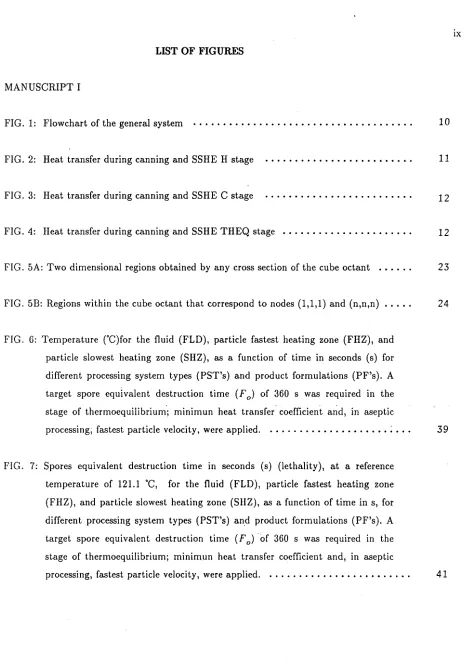
FIG. 4: Heat transfer during canning and 5SHE THEQ stage • • . • • . . . • . . • . 12
FIG. 5A: Two dimensional regions obtained by any cross section of the cube octant .•.... 23
FIG. 5B: Regions within the cube octant that correspond to nodes (1,1,1) and (n,n,n) ..•.• 24
FIG. 6: Temperature CC)for the fluid (FLD), particle fastest heating zone (FHZ), and particle slowest heating zone (SHZ), as a function of time in seconds (s) for different processing system types (PST's) and product formulations (PF's). A target spore equivalent destruction time (F0) of 360 s was required in the stage of thermoequilibrium"; minimun heat transfer" coefficient a~d, in aseptic processing; fastest particle velocity, were applied. . . • . . . • . • • ;... 39
FIG. 8: Enzyme equivalent destruction time in seconds (s), at a reference temperature of 121.1·C, for the fluid (FLD), particle fastest heating zone (FHZ), and particle slowest heating zone (SHZ), as a function of time in s, for different processing system types (PST's) and product formulations (PF's). A target spore equivalent destruction time (F0) of 360 s was required in the stage of thermoequilibrium; minimun heat transfer coefficient and, in aseptic
processing, fastest particle velocity, were applied. ..•••••..••••••••...•••. 43
FIG. 9: Nutrient equivalent destruction time in seconds (s) (lethality), at a reference temperature of 121.1 ·C, for the fluid (FLD), particle fastest heating zone (FHZ), and particle slowest heating zone (SHZ), as a function of time in s, for different processing system types (PST's) and product formulations (PF's). A target spore equivalent destruction time (F0) of 360 s was required in the stage of thermoequilibrium; minimun heat transfer coefficient and, in aseptic
processing, fastest particle velocity, were applied. ...••••••.•••••..•••.••• 45
FIG. 10: Product integrated equivalent destruction time in seconds (s), at a reference temperature of 121.1 ·C, for spores, enzyme, and nutrient, as a function of time in s, for different processing system types (PST's) and product formulations (PF's). A target spore equivalent destruction time (Fo ) of 360 s
was required in the stage of thermoequilibrium. . . • . . . • • . . 47
FIG. 11: Product fluid (FLD), and octant (1,1,1) region lethality (spores equivalent destruction time in seconds (s), at a reference temperature of 121.1 ·C), versus octant (n,n,n) region (cube center) lethality, for .different processing system types (PST's) and product formulations (PF's). A target spore equivalent destruction time (F0) of 360 s was required in the stage of thermoequilibrium; minimun heat transfer coefficient and, in aseptic processing, fastest particle
velocity, were applied. ... . . • . . . • • • . . . . • • . • . . • . . • . . . 49
/
.e
stage of thermoequilibriumj minimun heat transfer coefficient and, in aseptic processing, fastest particle velocity, were applied. . ..•.•.•....•.•••.•...•.
MANUSCRIPT II
Xl
51
FIG. 1: Program MAIN flowchart . . . • . • . . . • • . . . • . • . • . • . . . • . . . 74
FIG. 2: Thermoequilibrator (THEQ) length in m, as a function of deterministic THEQ velocity ratio (THEQVR), for different processing system types (PST's), product formulations (PF's), and convective heat transfer coefficient (hip)
values. A target spore equivalent destruction time of 360 s was required for the
slowest heating zone in the THEQ. ...•...•...••.••..•••••••...•. 87
FIG. 3: Enzyme equivalent destruction time in s, at a reference temperature equals to 121.1 °C, as a function of deterministic THEQ velocity ratio (THEQVR), for different processing system types (PST's), product formulations (PF's), and convective heat transfer coefficient (hip) values. A target spore equivalent destruction time of 360 s was required for the slowest heating zone in the THEQ.
FIG. 4: Nutrient equivalent destruction time in s, at a reference temperature equals to 121.1 °C, as a function of deterministic THEQ velocity ratio (THEQVR), for different processing system types (PST's), product formulations (PF's), and convective heat transfer coefficient (hip) values. A target spore equivalent destruction time of 360 s was required for the slowest heating zone in the THEQ.
89
91
FIG. 5: Thermoequilibrator (THEQ) length in m, as a function of random THEQ velocity ratio (THEQVR), for different processing system types (PST's), product formulations (P F's), and con vecti ve heat transfer coefficient (hip)
values. A target spore equivalent destruction time of 360 s was required for the
FIG. 6: Enzyme equivalent destruction time in s, at a reference temperature equals to 121.1 ·C, as a function of random THEQ velocity ratio (THEQVR), for different processing system types (PST's), product formulations (PF's), and convective heat transfer coefficient (hJp ) values. A target spore equivalent
destruction time of 360 s was required for the slowest heating zone in the THEQ.
FIG. 7: Nutrient equivalent destruction time in s, at a reference temperature equals to 121.1 ·C, as a function of random THEQ velocity ratio (THEQVR), for different processingsystem types (PST's), product formulations (PF's), and convective heat transfer coefficient (hJp) values. A target spore equivalent destruction time of 360 s was required for the slowest heating zone in the THEQ. • . • . . • • . . . • . . . . • . . • . • . . . • . • • • . . . . • • . . . .
FIG. 8: Absolute frequencies of truncated normal residence time ratio (RTR), andcorresponding thermoequilibrator velocity ratio (THEQVR), for different product formulations (PF's). . •...•....•...••..•...•••.•
FIG. !): Absolute frequencies of the thermoequilibrator length in m(THEQL), when the product consisting of beef in gravy without starch (PF=I), is processed in a scraped surface heat exchanger aseptic processing (PST=I). A target spore equivalent destruction time of 360 s, at a reference temperature of 121.1 ·C, was required for the slowest heating zone in the THEQ...•..•.••...•....•
FIG. 10: Absolute frequencies of the thermoequilibrator length in m (THEQL), for different processing system types (PST's), product formulations (PF's), and convective heat transfer coefficient (hJp) values. A target spore equivalent destruction time of 360 s, at a reference temperature of 121.1 ·C, was required for the slowest heating zone in the Til EQ . . . • . . . • . . . • .
FIG. 11: Probability to miss a lethality target (360s), and a nutrient retention percent target (80% minimum retention), for different processing system type (PST)-product formulation (PF) combinations, thermoequilibrator lengths (THEQL's) and different convective heat transfer coefficient (hJp ) values. . ...
95
97
99
99
101
FIG. 12: Nutrient reduction exponent for fluid (~N,f)' at system exit, as a function of decimal log of equivalent time (L( t E))' and fluid equivalent temperature (yE,f)' for different processing system type (PST)-product formulation (PF) combinations, and convective heat transfer coefficient (hfp ) values. A target spore equivalent destruction time of 360 s, at a reference temperature of 121.1
DC, was required for the slowest heating zone in the thermoequilibrator. . • • • . • • lOS
FIG. 13: Nutrient reduction exponent for the (1,1,1) octant region (~N
,
1)' at system exit, as a function of decimal log of equivalent time (L(tE )), and (1,1,1) region equivalent temperature (YE,
1)' for different processing system type (PST)-product formulation (PF) combinations, and convective heat transfer coefficient (hfp ) values. A target spore equivalent destruction time of 360 s, at a reference temperature of 121.1 DC, was required for the slowest heating zonein the thermoequilibrator. ...•..•..••••...•...•••••...•.••••• 107
FIG. 14: Nutrient reduction exponent for the (n,n,n) octant region (lRN
,
n)' at system exit, as a function of decimal log of equivalent time (L(tE )), and (n,n,n) region equivalent temperature (YEn)' for different processing system type,
(PST)-product formulation (PF) combinations, and convective heat transfer coefficient (hfp ) values. A target spore equivalent destruction time of 360 s, at a reference temperature of 121.1 DC, was required for the slowest heating zonein the thermoequilibrator. . . • . . . . • • . . . 109
FIG. 15: Decimal log of system exit equivalent time (EQU TIME LOG) versus fluid (FLD), octant (1,1,1) region, and octant (n,n,n) region system exit equivalent temperature (EQU TEMP), for different processing system type (PST)-product formulation (PF) combinations, and different convective heat transfer coefficient (hfp ) values. A target spore equivalent destruction time of 360 s, at a reference temperature of 121.1 DC, was required for the product's slowest
FIG. 16: Spores reduction exponent for the product slowest heating region (~Mn or
~Mf)' at system exit, as a function of decimal log of equivalent time (L(tE)), and equivalent temperature (yE,n orYE,f)' fordifferent processing system type (PST)-product formulation (PF) combinations, and different thermoequilibrator lengths (THEQL's). The convective heat transfer coefficient
SYMBOLS
A
Bi
D
Eu'u
=
in,g,out,a•
Eu'u
=
in,g,out,aFu'u
=
0,1gill
h
k
LIST OF SYMBOLS
: Cross sectional area (m2) : ER cross sectional area(m2)
: Incremental volume or can area (m2)
: slope factor in the electrical conductivity versus temperature line
: Biot number for any cube unit inside the beef cube octant. h 6
Bi=
k
P(dimensionless)
P
: Constituent concentration
: Time(s), atYo = 121.1 ·C, necessary to obtain a 90% (1 decimal log cycle) reduction a constituent concentration
: Time (s), at Yo = 121.1·C, necessary to obtain a 90% (1 decimal log cycle) reduction in constituent u concentration
: Error tolerance in simulation program. Units: ·C for-u
=
ajdimensionless for u= r, m
: Energy (J)
: Rate of Energy (w,w
=?)
: Sterility (F0 is a target at Yo
=
121.1·C, and Z=
10·C). Units: s: Energy generation rate per volume unit (Wa)
. m
: Convective heat transfer coefficient (m'!f.C)
: convective heat transfer coefficient at the fluid particle interface (m'!f·
C)
: Particle thermal conductivity (mu;,C)
: Octant edge length(m) L
n
: Lethality rate.Itis defined as the ratio of exposure time at Vo to exposure time at a temperatureVduring the time interval from
t
itote (dimensionless)
: Decimal logarithm of equivalent time (dimensionless) : ER heater length (m)
: Mass of the fluid contained in the reference volume product (product in can or incremental volume) (Kg)
: number of nodes or points equally spaced on the octant edge. Itis equal to the number of congruent segments into which the edge is divided plus 1
: Number of beef cubes contained in the reference volume product (product in can or incremental volume)
3
Q :Volumetric flow rate (~ ) in aseptic processing
~uv,u
=
M,Njv=
J,l,n : Reduction exponents (dimensionless)t :general time (s)
tu,u=i,e,E :Time(s)
lSt : Variable time step applied in Ilubroutine INTEGRAL (s)
(cOv ' v
=
min, max : time step bounds (s)V :Temperature CC)
V(ij,k) : Temperature CC) at (ij,k) octant node, and applicable to the corresponding octant region. i, j, k=l, 2, ...,n
Y~/' u
=
heVB
z
SUBSCRIPTS
1
a
ew
6t
e
er
: Temperature rC).
: Equivalent temperature rC)
: vector containing the plug flow fluid temperatures rC), in aseptic processing
:Fluid temperature rC) target at device u exit
: Overall heat transfer coefficient corresponding to H stage (m~C) : Volume (m3)
: Aseptic incremental or can volume (m3)
: Square voltage required for a given power in the ER heater. Units: Square Ohms
: Temperature increase rC) required to reduce D by 90% (by 1 log cycle)
: Temperature increase rC) required to reduce D u by 90% (by 1 decimal log cycle)
: (1,1,1) octant region : Absolute
: Cooling water
: Time increment. In aseptic processing, corresponding characteristic (mass, volume, area, number of beef cubes) refer to time interval from tj to tj
+
61E
ENZ
f
9
h
I
in
m
M
max
min
n
N
o
out
p
r
B
SUPERSCRIPTS
c
H
: Equivalent point : Enzyme
: fluid : generated : heater
: at lower end of time interval
-: Integrated measurement over the entire unit (octant, beef cube or can product)
: input
: Computer machine : Spores
: Maximum allowed value for characteristic : Minimum allowed value for characteristic : at (n,n,n) octant region
: Nutrient
: Reference value. Yo=121.1 ·C. : Output
: Particle : relative : stored
: Pressurized steam
GREEK LETTERS
B
p
U'u'u
=
t,pABBREVIATIONS
AVER BBROTH
C
ENZ DEST TIME ER
ER1
: specific heat (k/.C)
: Phase u specific heat(k:'C)
: congruent subintervals length on octant edge (m). 8
=)
D : Fluid volume fraction in product contained in can or incremental volume (dimensionless): Any of the three coordinate axis (xi' i = 1,2,3) : density
(k~)
m
: Phase udensity
(k~)
m: Phase u electrical conductivity at Yt = 25·C
(~),
S: Siemens, S= l/ohm: Constituent (spore, nutrient or enzyme) concentration at the time origin (ti = 0)
k
: Particle diffusivity, O:p =P ~ ,units: l/s
p p
: RTR population average or mean (dimensionless)
: Product formulation (PF) consisting of beef cubes in a fluid that does not contain starch
: Cooling device or stage
: Enzyme equivalent destruction time (s at Yo = 121.1·C) : Electrical resistance
ER2 FHZ FLD H
ISEED
MAXND
MAXNFE
NSAMPL ND
NUT DEST TIME ODE
PF
PROD DEST TIME PST
RTR
SHZ SSHE
: PST=2, PF=3 combination
: Product or beef cube fastest heating zone : Fluid
: Heating device or stage
: Initial seed, which is the initializing value for the argument of function GASDEV. Itis a negative number.
: Maximum number of octant edge nodes (number of congruent segments into which the octant edge is divided plus 1)
: Maximum number of functions evaluations by subroutine INTEGRAL when integrating a function from ti to te
: Size of the sample generated from a truncated normal population : Number of divisions that is, of congruent segments into which the octant edge is divided
: Nutrient equivalent destruction time (s at Yo
=
121.1·G) : Ordinary ·differential equation: Product formulation
: Product integrated equivalent destruction time (s at Yo
=
121.1·G) : Processing system type: Fastest particle residence time ratio, defined asthe ratio of the fastest particle residence time to either the mean particle residence time (H or C stage, assuming plug flow) or the mean fluid interstitial residence time (THEQ stage, under other than plug flow)
(dimensionless)
SSHEl SSHE2 STARCH
STn
THEQ THEQVR
RT TSTEP
: PST=l, PF=l combination : PST=l, PF=2 combination
: Product Formulation (PF) consisting of beef cubes in gravy with 3% starch (different electrical conductivities between the gravy and the beef)
: RTR population standard deviation (dimensionless since RTR is dimensionless)
: Thermoequilibrium device or stage
: Ratio of the fastest beef cube speed in the THEQ to the interstitial mean fluid velocity in the THEQ. Itis equal to l/RTR
(dimensionless)
: Retort Temperature CC)
Food processors are in need of instruments that allow them to foresee the performance of one or several thermal treatments, that may be applied on a given product formulation (PF), without actually building the physical system. Performance in this context is given by the microbiological, nutritional, and chemical quality of the food product, after being thermically treated. The ideal instrument, should allow for minor changes to PF in order to explore modifications thought to satisfy more the consumer.
There is a lack of instruments of the nature described, especially when the food product is a two-phase low-acid product, that includes large particles. The research project that is the subject of this dissertation, was undertaken with the objective to provide such an instrument: a simulation model, available to the food processor and food scientist, to allow them to simulate and evaluate a thermal treatment for a two-phase, low-acid food product . containing large particles.
There are several problems that one encounters when establishing such a model:
DEPENDENCE ON PF
alternative chemical reaction curves. The PF considered in the research project was lean beef in gravy with starch (~ 3%); .the enzyme and nutrient considered were respectively, peroxidase and thiamine. There is enough pertinent data on the chosen food product and the constituents of interest, to fully specified the simulation model.
This way to proceed is different from the usual way, as found in the related research literature, where instead of going from the product definition to the simulated system, researchers have gone from a general, sort of product independent model, to an elusive food product, despite the assertion, made at the outset, that the system is specific food product dependent.
EVERYWHERE UNCERTAINTIES
Examples of uncertainties are:
True parameter values and reaction curves. Parameters change with temperature.
In aseptic processing, either when a scraped surface heat exchanger (SSHE) or an electrical resistance (ER) heater is applied, the product flow through the system.
Behavior of the convective heat transfer coefficient (hlp) with respect to processing time and with respect to processing system type (PST) (especially SSHE versus ER aseptic processing)
True hlp: experimental minimum, low and high values (Chandarana et. aI, 1990; Chandarana and Gavin, 1989aj Sastry et. aI, 1990), pertinent to the PF considered, were applied. Flow pattern in the THEQ for aseptic processing: based on experimental findings (Berry, 1989;
Palmieri, 1991) pertinent to the PF considered, a truncated normal distribution for the residence time ratio (RTR) of the fastest particle in the THEQ, with mean (AVER) and standard deviation (STD) derived for experimental data, was assumed. Given a hlp value, probabilistic distributions for THEQ length, spore, enzyme, and nutrient equivalent thermal destruction times, etc., are estimated from a sample of 100 RTR's.
EXPECTED APPLICATION
If a target lethality is assumed in the model application, then the model is applied in design mode, and if THEQ length is assumed instead, it is applied in evaluation mode. The computerized model specification change with the application mode, since some of the algorithms are application mode dependent.
UNIFIED MODELFOR THE HEAT TRANSFER PROCESSES THAT OCCUR DURING
CANNING, SSHE AND ELECTRICAL RESISTANCE ASEPTIC PROCESSING OF FOOD
PRODUCTS THAT CONTAIN LARGE PARTICLES*
by
Jose F. Pastrana, Harvey J. Gold and Kenneth R. Swartzel
ABSTRACT
A unified general model for the heat transfer processes that occur within a food product subjected to canning or aseptic thermal treatment, is presented. Two principles are extensively used in the mOdel building process: system segregation and energy balancing. The model is summarized in an algorithm, whose specification is showed for different combinations of processing system type (PST) and product formulation (PF) with a single particle type. A discussion on the practical relevance of proper product identification in the case of aseptic processing, is included. Finally, an illustration is given on the results that can be obtained from the model algorithm application, in a comparative study of different PST-PF combinations.
INTRODUCTION
A food product may be therina:lly treated by pasteurization, conventional canning or aseptic processing. The purpose of aseptic processing is to endow the food product with commercial sterility, a condition in which the product is free of viable microorganisms with either public health significance, as well as those of non-health significance, capable of reproducing under normal non-refrigerated conditions of storage and distribution (FPI, 1989). When a food product is subjected to a thermal treatment, there are heat transfer processes that take place. The driving force of such processes is the temperature gradients within the product. This paper describes a model of. the heat transfer processes in thermal treatment of a food product consisting of a fluid medium with large particles. An example would be beef stew. The model is general enough to describe aseptic processing as well as conventional canning. It
relating to the design of aseptic processing equipment and as the basis for estimating the sensitivity of the degree of sterilization and of the quality degradation to errors in process control, to variation in product formulation and to variability of the physical characteristics of the food material. An important feature of the model is its ability to estimate temperature at the slowest heating locations, which is difficult or impossible to measure with current techniques.
In developing the model, the system structure is represented by defining relevant components, and by defining the input-output relations (exchanges of energy) between the components, as well as the inputs and outputs for the overall system. Processes modeled within the components include fluid flow, heat diffusion within fluid and particulate phases, heat transfer between the phases and, for electrical resistance (ER) heating, conversion of electrical to heat energy (for discussions on the modeling approach, see Gold, 1985, Zeigler, 1976). In a subsequent paper, we will report on the structure of a computer program based on the model discussed here (Pastrana et. aI, 1992b).
Larkin et. al (1989), Armenante et. al (1990) and Lee et. al (1990). In constructing the model presented in this paper, extensive use was made of the idea of local energy balances:
A solid particle as a subsystem, is first considered as the union of mutually exclusive and exhaustive regions, then energy balances are established for each region to arrive at a system of ordinary differential equations (ODE), which describes the heat transfer by conduction taking place within the solid particle.
Since some of the equations in the ODE system (those that correspond to the solid particle surface) depend on the surrounding fluid temperature, there is a need to know or estimate that temperature. This may be done in three alternative ways: by direct measurement (although the most accurate, it requires that the system be physically constructed), by fluid energy balances on incremental volumes in the system equipment (Sastry, 1986; Chandarana and Gavin, 1989aj Chandarana et. ai, 1989b; Larkin, 1990), and by assuming an average fluid temperature profile (Larkin, 1989j Armenante et. ai, 1990; Lee et. ai, 1990). In our model, we use the local energy balance principle following Sastry (1986), to obtain an estimate of theflui~ temperature profile as the product flows through the system. We make the simplifying assumptions that the fluid is well mixed (in the radial direction for aseptic processing and in all directions for canning), and that there is piston (plug) flow throughout.
The model proposed in this paper differs from Sastry's (1986), in several respects: In addition to the SSHE system, it includes electrical resistance aseptic and canning processing,
and also adds the cooling stage.
A target for the fastest heating zone (FHZ) temperature at heater exit
(y:,
j)' is established as in Chandarana and Gavin (1989a), Chandarana et. al (1989b), Larkin (1989,1990) and Lee et. al (1990).A target for the fluid temperature at system exit (y~,j)' is established. A similar target for the warmest zone proved to be too strong a requirement for a particular product formulation (PF), under ER aseptic processing (Pastrana et. all, 1992b)
Irregular shapes are not considered for the solid particles, since any irregular shape can be included in an appropriate imaginary regular shape, such as a sphere or parallelepiped.
THEORY
SYSTEM DEFINITION AND STRUCTURE
We are concerned with modeling changes in a food product, which consists of particles in a fluid medium. The relevant changes which are induced by the thermal treatment (canning, ER or SSHE aseptic thermal treatment) include microbial and spore load, enzyme concentration, nutrient retention and other measures of food quality. The thermal treatment consists of the following stages (shown with abbreviations which will be used): heating (H), thermoequilibrium (THEQ), and cooling (C). The H stage consists in the application of a heat source by means of pressurized steam (canning and SSHE aseptic processing) or an electrical current( ER aseptic processing). The product temperature at any point is expected to increase during the H stage. The THEQ stage follows immediately the H stage and consists of a holding stage during which the product is expected to reach thermal equilibrium, in which thermal gradients would disappear. The C stage follows immediately the THEQ stage. It consists of applying ~ heat sink by means of cooling water, so that the product temperature at any point is expected to decrease.
The thermal state of the system at any given time is specified by the product temperature distribution. The devices associated with each stage for the different types of thermal treatment are as follows:
DEVICE STAGE
H
THEQ
c
Canning Rotating retort at temperature below retort temperature (RT) and under pressurized steam. Rotating retort at temperature equal to RT, and under pressu rized steam.
Rotating retort under cooling water.
Aseptic SSHE or ER heater.
Stainless steel insulated tube.
FIG.1 shows a flowchart of the general system:
DEVICE 1 DEVICE 2 DEVICE 3
I
H stage1---+
1I
THEQ stage1---1
C stageI
time FIG. 1: Flowchart of the general system
SYSTEM INPUTS, OUTPUTS AND ENVIRONMENT
The input to the system is energy. For canning or SSHE aseptic processing, the main input energy is in the form of heat transfer from a heating medium. For ER aseptic processing, the main input energy is in the form of electrical energy delivered by subjecting the product to an alternating electrical current.The output from the system is energy. The main output energy is the form of heat transfer to the cooling medium.The environment is considered to be everything apart from the system that may transfer heat to, or receive heat from, the system. In particular, the environment includes the supporting systems needed to preheat the product, raise the heating medium temperature and lower the cooling medium temperature.
SYSTEM COMPONENTS, THEIR INPUTS AND OUTPUTS Component
1
Component
Z
It includes DEVICE 2 plus the heated particulate-laden product being already in thermoequilibrium. The input is the same as the output from component 1 and the output is heat transferred to component 3 in the form of a food product in thermoequilibrium.
Component~ .
It includes DEVICE 3 plus the particulate-laden product in thermoequilibrium being cooled. The input is equal to the output from component 2 and the output coincides with the system energy output.
The heating stage for canning and SSHE aseptic processing involves convective and conductive heat transfer processes as follows:
convective PARTICLE conductive PARTICLE
SURFACE CENTER
i
i
i
convection product-interior wall;i
conduction through wall; convective at steam-external walli
HEATING MEDIUM
FIG. 2: Heat transfer during canning and SSHE H stage
!
!
!
convection product-interior wall;!
conduction through wall; convective at water-external wall!
convective conductive PARTICLE
CENTER
COOLING MEDIUM
FIG. 3: Heat transfer during canning SSHE C stage
When the fluid is the FHZ during ER heating, the fluid and particle surface are also heat donors as for SSHE heating (FIG. 1). except that in that case the heating medium is the product itself.
FIG. 4 shows the convective and conductive heat transfer processes for the THEQ stage; the arrows go from fluid to ambient for aseptic processing, and from constant steam temperature to fluid for canning:
convective PARTICLE conductive PARTICLE
SURFACE CENTER
!l
!l
!
T
convection product-interior wall;!
T
conduction through wall; convective at surroundings-external wall!l
AMBIENT OR CaNST. TEMP. STEAM
MODEL BUILDING PROCESS Introduction
The model is designed to yield estimates , at any point in the processing system, of variables which depend upon temperature history of the food product. Some important variables which we consider are:
Nutritional quality variables:
Nutrient percent concentration.
Point or integrated nutrient equivalent thermal destruction times. Sterility variables:
Spores percent concentration.
Point or integrated spore equivalent thermal destruction times. Chemical variables:
Enzyme percent concentration
Point or integrated enzyme equivalent thermal destruction time
•
purposes is the one that contains the product's slowest heating zone (SHZ) , and second, the surrounding fluid temperature is known. As indicated in the INTRODUCTION of this paper, three ways to generate a carrier fluid temperature profile are: by direct measurement; by computation of fluid energy balances, and by assuming an average temperature profile. The second, which is the one followed in this paper, idealizes, for the purpose of generating a carrier fluid temperature profile, the existence of a thermodynamic control volume (Van Wylen and Sonntag, 1985). The coordinate system that allows the volume localization is a translating system along the horizontal axis (imaginary incremental volumel , assumed to move horizontally in a horizontal processing system).
Although the control volume contains, at a given instant, a thermally treated product, it is true that the product is still not well identified, since mass gets in and out the control volume. Should plug (piston) flow hold throughout for aseptic processing, then the problem of control-volume product identification would disappear.
Modeling assumptions
The following assumptions are made in order to simplify the model:
a) All solid particles are identical with respect to size , shape, and other relevant characteristics.
b) The product fluid In the reference volume is well mixed, so that fluid temperature is
uniform.
c) For canning, the resistance to heat transfer offered by the metal can wall, is ignored.
d) For aseptic processing, H stage exit FHZ temperature and C stage (system) exit fluid temperature equal to their targets, as indicated in the INTRODUCTION, and are set by
•
the operator. For canning, constant pressurized steam and cooling water temperatures, were fIxed; although the same fluid exit temperature target was required as for aseptic processing, no corresponding target was set, at the H stage exit.
e) Initial temperature distribution within the reference volume is uniform and equal to a constantYI at every point in the product.
f) For aseptic processing, a particular configuration is assumed where devices are straight, lined up horizontally, directly connected one after the other, and with no bends.
g) For ER heating, the following specific assumptions are made: all electrical energy is converted into thermal energy; the effect on temperature of the particle orientation relative to the electrical fIeld lines is negligible (reasonable for cubic shapes); the ratio between the solid and fluid electrical conductivities is invariant with temperature. h) Applicable hJp is the same for canning as for aSeptic processing.
Basic modeling principles
Two basic principles have been applied in the modeling building process. These are appropriate segregation of the system, and thermodynamic modeling of local energy balances. Appropriate segregation of the system:
First, the system is divided into three components, as indicated in the section SYSTEM COMPONENTS, THEIR INPUTS AND OUTPUTS.
Second, within each component, one of the identical (see assumption a)) solid particles is considered. In aseptic processing, the particle considered is the fastest moving particle. Third, a volume of product containing this particle is considered.
considered to be a thermodynamic subsystem (a partition of the solid particle that is suitable for numerical integration, is convenient here). The volume of product that contains the fastest moving solid particle, is also segregated into two thermodynamic subsystems: the fluid phase and the solid phase; the latter consists of the solid particles (beef cubes), each being partitioned identically.
Local energy balances:
An energy balance is an equality between the sum of the rates of energy inputs (sources), and the sum of the rates of energy uses. It is a generalization of the work-energy theorem of mechanics, which sometimes is referred to as the general form of the first law of Thermodynamics (Sears and Salinger, 1986).
Possible energy sources are:
Energy input (Ein )such as heat transfer input and energy generated (Eg) by the system resistance to an electrical current.
Possible energy uses are:
Energy output (Eout) such as heat transfer· output and thermal energy (E6) stored in
the form of internal energy.
An energy balance takes the form(Myers, 1976):
For a thermodynamic subsystem during canning or SSHE aseptic processing:
•
•
•
Ein
=
Eout+
E.since there is no heat generation in such cases (noelectric current is applied, as during ER heating). During ER heating:
•
•
•
E9
=
Eout+
E. since there is no heat transfer applied in suchcase.
by:
•
E -g - g"'V
Model algorithms to obtain reference volume temperature spatial distribution
The following algorithm allows the estimation of the temperature distribution in the reference volume for canning and, under the assumption that THEQVR=l, for aseptic processing. For the first algorithm iteration, t; is set equal to 0:
a) Consider the product in the reference volume to be subjected to a thermodynamic process that consists of heating (if product is in DEVICE 1), thermoequilibrium (if product is in DEVICE 2), or cooling (if product is in DEVICE 3) from time t; to time te,
te=t;
+
et, where et is a time increment (also called variable time step). Assume plug flow for aseptic processing.b) Partition each food particle in the reference volume identically into disjoint and exhaustive regions, and consider each region within the food particle to be a thermodynamic subsystem.
d) Obtain the needed extra ODE (see c) above), by performing an energy balance on the reference volume fluid.
e) Solve the system of ODE's, storing y/ in a vector of fluid temperatures'll/ for the aseptic processing case, so that the fastest particle surrounding fluid temperature can be computed later. These stored fluid temperatures will be referred to as plug flow fluid temperatures. In the numerical integration, a variable time step method that uses 4th and 5th order Runge Kutta schemes may be applied (Pastrana et. aI, 1992c). At time tout this gives an estimate of the spatial temperature distribution.
f) Set ti = te
,
and take last temperature estimates as initial estimates.g) Repeat the whole process until te becomes equal to the processing system exit time.
For aseptic processing, the temperature spatial distribution of the fastest food particle is computed by applying the following algorithm, first settingti = 0:
a) Consider the product enclosed in a reference volume Qx
of
that contains the fastest particle, where Qis the volumetric flow rate, and a thermodynamic process (heating, thermoequilibrium or cooling) from ti to te, te=ti+6t, on that product.b) Partition the fastest food particle into disjoint and exhaustive regions, and consider each region included in the food particle to be a thermodynamic subsystem.
c) Establish energy balances for each of the regions of the fastest particle, expressing them as a system of ODE's.
d) Find the temperature of the fluid surrounding the fastest particle by applying the stored plug flow fluid temperature profile:
The surrounding fluid for the fastest particle, has a temperature approximately equal to the stored plug flow fluid temperature that corresponds to the above plug flow fluid time (entry in 1/1associated to time less or equal to such plug flow time).
e) Solve the system of ODE's applying the surrounding fluid temperature obtained in the previous step. At time te this gives an estimate of the spatial temperature distribution of the product enclosed in the reference volume containing the fastest particle.
f) Set tj
=
teand take the last temperature estimates as initial estimates.g) Repeat the whole process until te is equal to the processing system exit time.
Residence time considerations in aseptic processing
The stored plug flow fluid temperatures allow the computation of the temperature distribution for the fastest particle, under various assumptions concerning residence time at high product flow rates:
a) Plug flow in each device. This could be a reasonable scenario when the product flow is turbulent throughout.
b) Plug flow in the H and the C stages, but bimodal normally distributed residence time ratio (RTR) in the THEQ. This scenario may be appropriate when the flow is turbulent in the Hand C. There is experimental evidence, such as with the PF's considered by us, that the RTR distribution is likely to be bimodal normal in the THEQ (Berry, 1989; Dutta and Sastry, 1990; Palmieri, 1991). This is the residence time scenario chosen for the model applications (Pastrana et. aI, 1992b).
Taeymans et. aI, 1985). As pointed out in b) immediately above, there is experimental evidence that suggests the possibility of a bimodal normal RTR in the THEQ, for the PF's considered by us. This scenario may be modified by assuming plug flow in the THEQ, when the flow there, is turbulent.
d) Plug flow in the electrical resistance (ER) heater, and THEQ, and exponentially distributed RTR in the C. This residence time scenario may be appropriate when there is turbulent flow in the ER heater and THEQ, and there is mixing in the radial and axial direction in the C.
Model equations
The model equations consist of a system of ODE's derived from the energy balances performed according to the algorithms described previously. The specific form of the equations depend on several factors:
Particle shape. This may be regular (spherical, cubic, etc.) or irregular.
Manner in which the particle is segregated into regions. The type of segregation depends on the particle shape, and presupposes a strategy to solve the system of ODE's (finite difference, finite element, etc.).
Region location within the particle. The region location is described by the corresponding node location: in the interior, at the boundary and/or surface. In the case of the cubic shape, considered in the model applications (Pastrana et. aI, 1992b, 1992c, 1992d), surface regions correspond to: non-edge, edge but not at the corner, and corner nodes. Thermal treatment stage. The heat transfer processes change, and there are different pertinent
parameters in each stage.
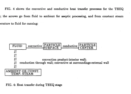
uniform fluid temperature, there is symmetry in the convective heat transfer from (to) the fluid to (from) the particle faces, which allows consideration of just one octant of the cube in setting the system of ODE's. The cube octant was segregated into small volume units or regions, by applying the finite difference method (Myers, 1971).
To illustrate, when the octant edge is divided into 3 congruent segments, the number of discrete points on the octant edge (n) is 4: two endpoints and two interior points. Letting (ij,k) represent an arbitrary point in the resulting octant grid, ij,k=1,2,3 or 4, there are 64 points (ij,k), called nodes, each of which can be monitored as far as spore, enzyme, and nutrient thermal destruction. The idea is to assign an octant volume unit, that is, an octant region, to each node, and assume uniform thermal conditions for the octant region. Following Myers's nodal point arrangement (Myers, 1971), octant regions are assigned to the nodes so that any octant cross section, yields regions in two dimensions, as described in FIG. 5A. The regions assigned to nodes (1,1,1), and (n,n,n) (lower left and upper right regions in FIG. 5B) are of particular interest in the applications, because one of them corresponds to the fastest beef cube· SHZ, while the other to· the SHZ (See ILLUSTRATION Section in this paper, and Pastrana et. aI, 1992b and d).
I
I
r-1i I':l. II
1'-' H
, II I I' - I
;
!
I
ii
I
i
I
~I
1_ !i
)~
H
I II
'--'J
I
!
I
i-l
~~
---t.---r---r---T---Jlr---i
l
II !J. I I
1 I!
' - - '
,---,
11 1
, I I ,
l - - l
r--J
!9 i ,~ I
I I
L...-J
! " I
!3
!I I
l - - l
FIG. 5A: Two dimensional regions obtained by any cross section of the cube octant.
Axis identification is as follows, assuming that the cube is centered at the origin, and its sides lie on the coordinate system axes:
The energy balances for the fluid and regions within a particle, established according to the above algorithms steps, include when applicable, the rate of thermal energy generated, the rate of heat transferred by convection to or from the fluid, the rate of heat transferred by conduction to or from neighboring particle regions, and the rate of energy stored in the form of internal energy. As an example, the fluid energy balance includes the following energy sources and uses:
Sources:
Thermal energy generated (as in the ER).
Heat transferred by convection from a heating medium (as in canning, SSHE, and depending on PF, in ER processing).
Uses:
Energy stored in the form of internal energy.
Energy transferred by convection to the particles (as in canning and SSHE and, depending on PF, in ER processing).
The equations that appear below were derived by Jose ·Pastrana. In them, vs=O for the canning H stage and SSHE aseptic processing (since no electrical current is applied),
Uh
=
0 for ER heating (there is no heat transfer through the ER wall), and the parameters mlit' Alit' N lit' V lit' and YBt depend on the processing' system considered.Derivative of fluid temperature
~
. 2-7ff=l.O/(mlit
x
'Yj)x
(Uhx
Alitx
(YBcYj)-h jpx
24.0x
Ix
Nlitx
(YrY)+((Vlitl(Aer
x
Ler))2)x
vsx
(J'jx
(l.O+bj(yr25.O))x c x
(Aer2)/Vlit)In the case of SSHE and ER aseptic processing, this derivative depends on the time step Ct,
Derivatives of cube octant temperatures a) At octant interior nodes: .
~ij,k)=(a/62)
X(y(i-lj,k)-6.0x
y(ij,k) + y(i+lj,k)+y(ij-l,k) + y(ij+l,k) + y(ij,k-l) + y(ij,k+l)+
((6/ Ler)2)xVBX(TPx(l.O+mpx(y(ij,k)-25.0»/kp } ij,k=2, n-l
b) At nodes in the three cube octant faces that have direct contact with the fluid. A convective boundary condition was considered when establishing the corresponding energy balances.
bl) Nodes not at the edges:
~~(lj,k)=(a/62)
x
(2.0x
Bix
(Yry(lj,k» +y(lj-I,k)-6.0
x
y(lj,k) + y(lj+l,k) + y(lj,k-l) + y(lj,k+l)+2.0x
y(2j,k)+4.0
x
((6/(2.0x
Ler»2)x
vsx
(Tpx
(l.O+mpx
(y(lj,k) -25.0»/kp )'j,k=2, n-I~~(ij,I)=(a/62)
x (2.0 x Bi x(yry(ij,l» +y(i-Ij,l)-6.0xy(ij,l) + y(i+Ij,l) + y(ij-l,l) + y(ij+l,1)+2.0xy(ij,2)+
((6/ Ler)2)xvsX(TPx(l.O+m
px(y(ij,l)-25.0»/kp } i,j=2, n-l
~~(i,1,k)=(a/62)
x
(2.0x
Bix
(yry(i,l,k» +y(i-l,l,k)-6.0x y(i,l,k) + y(i+l,l,k) + y(i,l,k-l) + y(i,1,k+l)+2.0 x y(i,2,k)+
((6/ Ler)2) x vs x(Tpx(l.O+mpx(y(i,1,k)-25.0»/kp } i,k=2, n-l
y(l,n,k)=y(l,n+l,k) and y(i,l,n)=y(i,l,n+ 1).
.
~~(1,1,k)=(0:/02)
X(4.0 xHix(yr y(1,1,k»+2.0 xy(1,2,k)-6.0 x y(l,l,k) + y(l,l,k-l) + y(1,1,k+l)+2.0 x y(2,1,k)+
4.0 x «0/(2.0 xLer»2)xVB X qPx (l.O+mpx (y(1,1,k)-25.0»/kp )' k=2, n-l
~~(1,n,k)=(0:/02)
x (2.0 x Bi x(yry(l,n,k))+4.0 x y(1,n-l,k)-8.0 x y(l,n,k) + y(l,n,k-l) + y(1,n,k+l)+2.0 x y(2,n,k)+ 4.0 x «0/(2.0 xLer»2)xVBX q Px (l.O+mp x (y(1,n,k)-25.0»/kp ). k=2, n-l
~~(lj,1)=(0:/02)
x (4.0 x Bi x(yr y(lj,1»+2.0 x y(lj,2)-6.0 x y(1j,l) + y(lj-l,l) + y(lj+l,1)+2.0 x y(2j,1)+4.0 x «0/(2.0 xLer»2)xVBXqPx (l.O+mpx (y(lj,1)-25.0»/kp )'j=2, n-l
~~(lj,n)=(0:/02)
X(2.0 x Bi x (y r y(lj,n»+4.0 xy(lj,n-l)-8.0 x y(lj,n) + y(lj-l,n) + y(lj+l,n)+2.0 x y(2j,n)+
4.0 x «0/(2.0 xLer))2) xVBXqPx (l.O+mpx (y(lj,n)-25.0))/kp ).j=2, n-l
~~
(i, 1,1 )=(0:/02)x (4.0 x Bi x(yry(i,l,l ))+2.0 x y(i,2, 1)-6.0 x y(i,l,l) + y(i-l,l,l) + y(i+l,1,1)+2.0 x y(i,1,2)+«0/L
er)2)xVBXqPx (l.O+mpx (y(k,1,1)-25.0»/kp ). i=2, n-l~~(i,n,1)=(0:/02)
x (2.0 x Bi x(yr y(i,n,1»+2.0 x y(i,n,2)-8.0 x y(i,n,1)+4.0 x y(i,n-l,l) + y(i-l,n,l) + y(i+l,n,l)+c) At nodes in the three octant faces that have direct contact with neighboring cube octants. A symmetric boundary condition was considered when establishing the corresponding energy balances. The symmetric boundary condition was applied by imposing equalities such as:
y(n,l,k)=y(n+l,l,k) and y(n,n,k)=y(n,n+l,k).
c1) Nodes not at the edges.
~~(nj,k)=(a/82)
x (y(nj-l,k)-8.0 x y(nj,k)+y(nj+l,k) + y(nj,k-l) + y(nj,k+l)+4.0 x y(n-lj,k)+
4.0 x ((8/(2.0 xLer))2)x vsX0"Px (1.0+mpx (y(nj,k)-25.0))/kp )' j,k=2, n-l
~~(ij,n)=(a/82)
x (4.0 x y(ij,n-l)-8.0 x y(ij,n)+ y(i-lj,n) + y(i+lj,n) + y(ij-l,n) + y(ij+l,n)+((8/ Ler)2)x vsX0"P X(1.0+mpx (y(ij,n)-25.0))/kp } ij=2, n-l
~~(i,n,k)=(a/82)
x (y(i,n,k-l)-8.0 x y(i,n,k)+y(i,n,k+l) + y(i-l,n,k) + y(i+l,n,k)+4.0 x y(i,n-l,k)+
((8/ Ler)2)x vs x0"Px (1.0+mp x (y(i,n,k)-25.0))/kp ), i,k=2, n-l
~~(n,1,k)=(a/62)
x (2.0 x Bi x (Yry(n,1,k»+2.0 x y(n,2,k)-8.0 x y(n,l,k) + y(n,l,k-l) + y(n,1,k+l)+4.0 x y(n-l,l,k)+4.0 x ((6/(2.0 xLer»2) x vsX q Px (1.0+mp x (y(n,1,k)-25.0»/kp } k=2, n-l
~~(n,n,k)=(a/62)
x (4.0 x y(n,n-l,k)-lO.O x y(n,n,k)+ y(n,n,k-l) + y(n,n,k+l)+4.0 x y(n-l,n,k)+4.0 x ((6/(2.0 xLer»2) x vsXqPx (1.0+mp x (y(n,n,k)-25.0»/kp )' k=2, n-l
~~(nj,1)=(a/62)
x (2.0 x Bi x (Yry(nj,1»+2.0 x y(nj,2)-8.0 x y(nj,l) + y(nj-l,l) + y(nj+l,1)+4.0 x y(n-lj,l)+4 .0 x ((6/(2.0 xLer»2) x vsXqPx (1.0+mpx (y(nj,1)-25.0»/kp )'j=2, n-l
~~(nj,n)=(a/62)
x (4.0 x y(nj,n-l)-lO.O x y(nj,n)+y(nj-l,n) + y(nj+l,n)+4.(} x y(n-lj,n)+
4.0 x ((6/(2.0 xLer»2) x vsXqPx (l.O+mpx (y(nj,n)-25.0»/kp )'j=2, n-l
~~(i,1,n)=(a/62)
x (2.0 xBix (Yry(i,l,n»+4.0 x y(i,l,n-l)-8.0 x y(i,1,n)+2.0 x y(i,2,n) + y(i-l,l,n) + y(i+l,l,n)+((6/ Ler)2) x vsXqPx (l.O+mpx (y(i,l,n)-25.0»/ kp} i=2, n-l
~~(i,n,n)=(a/62)
x (4.0 x y(i,n,n-l)-lO.O x y(i,n,n)+(i-l,n,n) + y(i+l,n,n)+4.0 x y(i,n-l,n)+
d) At corner nodes.
~~(1,1,1)=(2.0
x0:/62)x (3.0 x Bi x (Yry(l,l,l)) + y(1,2,1)-3.0 x y(l,l,l) + y(1,1,2) + y(2,1,1)+2.0 x «6/(2.0 xLer))2)xVB Xupx (1.0+mpx (y(1,1,1)-25.0))/kp )
~~
(1,1,n)=(2.0 x0:/62)x (2.0 x Bi x(yry(l,l,n)) + y(1,2,n)-4.0 x y(1,1,n)+2.0 x y(l,l,n-l) + y(2,1,n)+2.0 x «6/(2.0 xLer))2)xVBXupx (1.0+mpx (y(1,1,n)-25.0))/kp )
~~(1,n,1)=(2.0
x0:/62)x (2.0 x Bi x (Yry(1,n,1))+2.0 x y(1,n-l,1)-4.0 x y(l,n,l) + y(1,n,2) + y(2,n,1)+2.0 x «6/(2.0 xLer))2)xVBXupx (1.0+mpx (y(1,n,1)-25.0))/kp )
~~(1,n,n)=(2.0
x0:/62)x (Bi x(Yry(l,n,n))+2.0 x y(1,n,n-l)-5.0 x y(1,n,n)+2.0 x y(n,n-l,n) + y(2,n,n)+ 2.0 x «6/(2.0 xLer))2)xVBXupx (1.0+mpx(y(1,n,n)-25.0))/k p)
~~(n,1,1)=(2.0
x0:/62)x (2.0 x Bi x(y ry(n,l,l))+y(n,2,1)-4.0 x y(n,l,l) + y(n,1,2)+2.0 x y(n-l,n,l)+
2.0 x «6/(2.0 xLer))2)xVBXupx (1.0+mpx (y(n,1,1)-25.0))/kp )
~~(n,1,n)=(2.0
x0:/62)x (Bi x(Yry(n,l,n))+ y(n,2,n)-5.0 x y(n,1,n)+2.0 x y(n,1,n-l)+2.0 x y(n-l,l,n)+~~(n,n,1)=(2.0
x0:/02)X(BiX(Yry(n,n,l)) + y(n,n,2)-5.0Xy(n,n,1)+2.0Xy(n,n-1,nn)+2.0Xy(n-1,n,1)+2.0X«0/(2.0XLer))2)XvsX(TPx (1.0+mpX(y(n,n,1)-25.0))/kp )
~~(n,n,n)=(2.0
X0:/02)X(2.0Xy(n,n-1,n)-6.0Xy(n,n,n)+2.0Xy(n,n,n-1)+2.0Xy(n-1,n,n)+
2.0
X
«0/(2.0XLer))2)XvsX(TP X(1.0+mpX(y(n,n,n)-25.0))/kp )Kinetics
As indicated in the Introduction of this section, the model was designed with the goal of obtaining estimates of variables which depend upon the temperature history of the food product. Once an estimate of the temperature spatial distribution is available for the product enclosed in the reference volume (containing the' fastest particle in the case of aseptic processing), the evaluation of any temperature dependent variable, is straightforward:
a) Point equivalent thermal destruction time for spores, enzymes and nutrients. The computation is done by applying the General Method of accumulated lethality computation (Pflug, 1990). For spores (of Clostridium Botulinum, say), this method was applied in the time interval from tj to tefor any of the product elements (fluid and
beef cube regions), by obtaining the point equivalent destruction time or kill time (F0) (Pflug, 1990), at the reference temperature (Yo' Yo = 121.1 ·C). The kill time is equal to the product of the time interval length (te - tj ), by the lethality rate (L) (ratio of
exposure time F0 at the reference temperature yo to exposure time F at a temperature y
Fo=(te - ti )xL, at the fluid or cube octant region with center node (ij,k). When the Bigelow model holds for relative times of thermal destruction (Pflug, 1990):
The accumulated kill time (sterility), for a relatively long time interval is computed by adding the kill times of a partition of subintervals. For constituents such as enzymes (peroxidase for example) or nutrients (thiamine for example), the same procedure is applied to obtain the corresponding equivalent destruction times.
b) Concentration of spores, enzymes and nutrients. The following formula is applied to compute the concentration Ce in any product element at time te , given an initial concentration ep at timetj
=
0:An alternative way of obtaining Ce is by applying actual time F, instead of kill time
F0' but adjusting the D values (Teixeira et al., 1964; Teixeira and Shoemaker, 1989).
The total concentrations are obtained by adding the products CeX product element
volume.
c) Integrated equivalent destruction times Flat time te for the product included in the reference volume. The initial concentration ep at time tj
=
0, and the concentration Ce at time te must be known in order to apply the following formula (Stumbo, 1965):ILLUSTRATION
Two alternative PF's of beef in gravy were considered, one without starch, denoted as BBROTH, and other containing 3% crosslinked starch, denoted as STARCH2• The thermal processing of each PF was simulated for each processing system type (PST): SSHE aseptic (PST=l), ER aseptic (PST=2), and canning (PST=3). A lethality target of 360 seconds (s) at a reference temperature equal to 121.1 ·C, was required for the THEQ stage. The results that appear in FIGURES 6 to 10 were obtained under worst case conditions: minimum convective heat transfer coefficient (hip)' and for aseptic processing, maximum fastest particle velocity ratio in the thermoequilibrator (THEQVR=2). The equivalent destruction times shown in the figures, are given at a reference temperature (y,.), equal to 121.1 ·C (250T).
Although all PST's were required to have the same system exit fluid temperature (32.2·C), a pressurized steam constant temperature was assumed for PST=3 (115.6 ·C), and a target fluid temperature (140 ·C) at H exit, was imposed for PST=l and PST=2. Constant cooling water temperature was also assumed for PST=3 (18.3 ·C). Adjustable pressurized steam and cooling water temperatures were considered for PST=l and PST=2.
(n.n,n), is the octant (particle) slowest heating zone (SHZ) (FIG.6). For a PST and PF combination where the fluid is the SHZ, see Pastrana et. al (1992 b).
SSHE aseptic processing (PST=1) for BBROTH, takes around half the time as canning (PST=3) (FIGS. 6A, 6B, 6C), and for STARCH, it takes approximately 80% of the canning time (FIGS. 6D, 6E, 6F). ER aseptic processing (PST=2) for STARCH, takes the least time where compared to PST=1 and PST=3 (FIGS. 6D, 6E, 6F). The time PST=2 takes is about 33% that for PST=1, and about 25% that for PST=3 (FIGS. 6D, 6E, 6F).
As far as spores equivalent destruction times for the fluid, cube octant (particle) FHZ and cube octant (particle) SHZ, PST=3 consistently shows lower values than PST=1 for BBROTH (FIGS. 7A, 7B, 7C) and STARCH (FIGS. 7D, 7E, 7F), and than PST=2 for STARCH (FIGS. 7D, 7E, 7F). PST=! appears to be a more effective sterilizing system than PST=3, for BBROTH (FIGS. 7A, 7B, 7C): at system exit, PST=3 has an accumulated lethality, at the particle SHZ, approximately equal. to 82% of that for PST=!. When PF is changed to STARCH, the lethality accumulated for PST=! and PST=3 in the particle SHZ at system exit, is approximately the same (FIGS. 7D, 7E, 7F). PST=2 is the most effective of the three PST's for STARCH (FIGS. 7D, 7E, 7F): at system exit, PST=2 delivers, at the particle SHZ, approximately twice the lethality delivered by PST=! or PST=3 (FIGS. 7D, 7E, 7F).3
With respect to enzyme equivalent destruction times at processing system exit, for fluid, particle FHZ, and particle SHZ, PST=3 shows lower values than PST=1 (FIGS. 8A, 8B, 8D, 8E), except for the particle SHZ (FIGS. 8C, 8F). PST=2 corresponding values for STARCH do not show a definite pattern, since for fluid the value is between those of PST=3 and PST=1 (FIG. 8D), for the particle FHZ the value is the greatest (FIG. 8E), and for the
particle SHZ it is the lowest (FIG. 8F).
With respect to nutrient equivalent destruction times for particle FHZ, and particle SHZ, PST=3 shows higher values than PST=! at system exit for BBROTH (FIGS. 9B, 9C); for STARCH, however, the corresponding difference is greatly reduced (FIGS. 9E, 9F). PST=3 shows lower fluid nutrient equivalent destruction times than PST=! (FIGS. 9A, 9D). PST=2 shows consistently lower fluid, particle FHZ, and particle SHZ nutrient equivalent destruction times, at system exit, than PST=!, and PST=3 (FIGS. 9D,9E, 9F); in particular, PST=2 has a system exit nutrient equivalent destruction time, at particle SHZ, of about 60% of that for PST=! and about 53% of that for PST=3 (FIG. 9F).
By following criteria for individual responses optimization, choices may be established for the PST's:
CRITERIA PF PST CHOSEN
High sterility 1 I
at SHZ
2 2
High enzyme I 3
destr. at SHZ
2 3
Low product nu- l !
trient destruct.
2 2
enzyme reactivation problem, although at system exit, the enzyme equivalent destruction time for particle SHZ ( FIG. 8), are well above a target enzyme equivalent destruction time of 371 s to ensure at least 99.9% enzyme (peroxidase) destruction, assuming a first order reaction and a decimal reduction time, when Yr=121 ·C, equal to 185.4 s (Yamamoto et. aI, 1962; Chandarana and Gavin, 1989a).
A choice for PST=3 can be justified by the following arguments: spore equivalent destruction time for the particle SHZ, at THEQ exit, is above the target F0' F0=360 s (by design), so that there is no lethality problem; the nutrient equivalent destruction time for the fluid is below a maximum target nutrient equivalent destruction time of 2348 s (FIG. 9A and FIG. 9B), to ensure no more than a 50% nutrient destruction at the product FHZ, assuming a first order reaction for nutrient destruction and a decimal reduction time, when Yr=121.1 ·C, equal to 7800 s (Feliciotti and Esselen, 1957; Chandarana and Gavin, 1989a) . When cost is considered, the choice is in favor of PST=3, which is the cheapest of the three PST's considered.
e
39'50
!M1
150Lf}]]
150 ][ID
'6O
~
'60 \60 ,'3O '30 130
120 120 120
[j5ST
=
3' ,IPST=
3 'PSJ~--~-3., '0
J-I
I 110 I "0II I :.l I w
r I I
•
Il)
100 I J 100 I J 100
~ I ~
( I ( I (
r I I
,
IlII 10
,
w 10 I w tol I l f I
1 I 1 I 1
..
so I :.l so I W so~
,
,
I ~t
0 70 I
..
70..
70J f I I
~
,
'"
•
so
,
10 SOI I
'0 I '0 50
I
,
-0 f -0 60
I
I
JO I JO 30
: 0
1
~
i 20 • 20
0 7'0 ''00 22'0 JOOO a HO "00 2150 3000
°
750 "00 ::'0' 3000I'"E
"0
[[Q}'
1'0[@'
150lliE1
, 6O '_0 \60
'30 IJO
~
130,
120 '20 120
PST _3 I (§T::3 f.E..ST=3'
, '0
"01-I ItO
"
'001
4 I w
r I PST
=
1,
IJ J
'001
I J 100
~
,
~( ( I (
r 10 r 10
f
Il 90"
l,
"
w10
j
I I
1 1 I 1
II so
~
..
I '
,
~ w~ 10°
•
10PS~T
~=
..
10 ,PST - 2\..
7021 t
,
I~
..
,
•
10 10 10
'0 i '0 50
~ l -0 ~
\
_0 60,
,
t ]0 30 JO20 20 20