IJEDR1504179
International Journal of Engineering Development and Research (www.ijedr.org)1038
PV-WIND Grid Connected Voltage Source Converter
Using PI Fuzzy Controller
1Bhumika Barange,
1Student of Electrical Engineering in Specialization of Power Electronics 1Rungta College of Engineering and Technology , Bhilai
________________________________________________________________________________________________________
Abstract - Power system and renewable applications have widely applied 3-phase grid connected converter. Conventionally, the power system is employed by standard decoupled d-q vector control mechanisms. Recent studies suggest that the dynamics systems in limitation are applicable in this system. This dissertation looks into how to moderate such limitations consuming a Fuzzy-PI to control a power system-connected rectifier/inverter. The Fuzzy-PI implements a dynamic rule book and fuzzy rules. To improve presentation and solidity under disturbance, additional strategies are covered, comprising the procedure of integrals of error signals to the network inputs and the maiden appearance of grid disturbance voltage to the outputs of a fuzzy system. The performance of the Fuzzy PI controller is studied under characteristic vector control situation and compare beside predictable vector control methods, which makes that the fuzzy vector control strategy proposed in this makeup is effective. Uniform in dynamic and power converter transferring atmospheres, the fuzzy vector controller indications a substantial ability to follow quickly moving mention commands, accept system instabilities, and gratify mechanism desires for a criticized power system.
IndexTerms – PI, DC-Link, fuzzy, grid converter and inverter.
________________________________________________________________________________________________________
I.INTRODUCTION
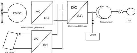
The Environmental friendly renewable energy technologies such as solar energy and wind energy based systems are among the fleet of new generating technologies driving the demand for distributed generation of electricity. Power Electronics has igni ted the next technical revolution and enables the connection of distributed generation (DG) systems to the power system. Hence the increasing power demand will be met by Distributed Generation (DG) system which is founded on renewable energy sources such as wind power, solar power and small hydro power etc. [1] -[3].In parliamentary law to ensure sinusoidal current injection into the grid, these organizations need to be checked. Simply, their intermittent characteristics give them poor controllability [4].Grid connected inverter plays a vital role in maintaining voltage at the degree of common coupling (PCC) constant. The grid code requirements such as grid stability, fault ride through, force control and grid synchronization, and so forth should be met b y the power plant operator for the reliable operation of utility grid based on DG system. The synchronization with utility voltage vector is the major event associated with the DG system [5].The information about the phase angle of utility voltage is tracked accurately to control the flow of active and reactive power and to move around on and off power devices.
With the exhaustion of natural resources and accelerated demand of conventional energy, the problems of energy famine and environmental pollution in the world have become of much importance that forced the planners and policy makers to look for alternative resources.
United wind-PV hybrid generation system utilizes the solar and wind resources for electric power generation hidden data and solar renewable sources individually have very uncertain behaviour. Solar energy is present throughout the day, but because of the sun intensity and uncertain shadows of the clouds, trees, birds attach the solar irradiation a level varies. Due to this cause solar energy is unreliable and less practiced.
A form of solar energy is wind. The wind flow patterns are changed due to the bodies of water and vegetation, uneven heating of the air by the sunlight, wind flow, the earth terrains. Wind turbine converts the kinetic energy in the wind into mechanical then to electrical by rotating the generator which is connected internally [1]. Twist is very irregular in nature, but large amount of power can be pulled away from it because of this drawback of wind energy it is an unreliable and less used.
Hence the use of the hybrid generation system is better than individual wind or individual PV generation system [6]. It overcomes the demerits of individual system. The system reliability can be increased by the grid interface of the hybrid generation system.
Load
AC DC
DC DC
PMSG
DC AC
Transformer Grid Common DC-Link
Direct-drive generator
PV Array
Inverter Converter
IJEDR1504179
International Journal of Engineering Development and Research (www.ijedr.org)1039
Small Signal Model of 1-Φ Inverter:-The primary aim of studying small signal model is to predict low frequency component present in the output voltage [6].The magnitude and form of this component depend not merely on the duty cycle variation, but besides the frequency response of the convertor. It is held by employing a deliberate perturbation around the operating point and then linearzing it at that point. The 1-Φ full bridge VSI system is illustrated in Fig.1.1.L O A D
C
SUPPLY
+
-S3
S2 S1
S4
L
Vc
Rc
Vdc
Fig.1.1 Schematic diagram of 1-Φ inverter to be modeled
The inverter in the above figure is being modeled and analyzed with an LC filter on the load side which considers R as load. Let us consider L is filter inductance𝑅𝐶Is damping resistor, C is filtered capacitor, or is loaded resistance, 𝑆1, 𝑆2, 𝑆3, 𝑆4Are switches
and 𝑉𝑑𝑐
The main purpose of using the damping resistor is to damp out the oscillations occurring due to the use of LC filter resonance.
Control Strategy for 1-Φ Inverter A control strategy is to be used to produce the output potential of the inverter being sinusoidal and hence to reduce THD in it. In this work an ACC [7] has been enforced to control the inductor current and PI controller or Resonant controller for controlling output voltage.
Current Control Scheme
An ACC is having an advantage over a peak current controller of adding a high increase in the forward control path and thus reduces the steady state error [7].Here the inductor current has been averaged over a shift point. And digital implementation of the current controller introduces a sampling delay. This delay yields 1 0 phase lag at the half of switching frequency. So, digital delay of one switching period is introduced in the current loop.
Gc(s)
RD(s)
F(s)
GiLd(
s)
Ri
Vref
+
-Current controller
Current loop
iL
ˆ
dˆ
iLˆ
Fig 1.2 Control loop for ACC strategy
The reference value of inductor current is generated from the output of voltage control loop discussed in the next section. A current sensor is being used to sense inductor current and its gain Ri is considered for controller design. In this research work its value is taken as 0.2. The transfer function of the design of the current loop is the ratio between duty cycle to output current 𝐺𝑖𝐿𝑑(𝑠)and is given by equation (1) which has been deduced from small signal model of inverter (Fig.2.4) by keeping 𝜐̂𝑑𝑐 = 0.
𝐺𝑖𝐿𝑑 (= 2𝑉𝑑𝑐
Z+sL𝑠) (1)
Where Z= load impedance is given by equation (4.16) Z = (𝑅𝑐𝐶.𝑠+1) 𝑅
𝐶.𝑠(𝑅𝑐+𝑅)+ 1 (2)
Fig.1.3 Bode plot of 𝑮𝒊𝑳𝒅(𝒔)
As shown in the bode plot of GiLd(s)phase cross over frequency is 10kHz which gives flatter response to inductor current which
IJEDR1504179
International Journal of Engineering Development and Research (www.ijedr.org)1040
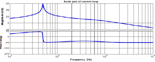
Fig.1.4 Bode plot of the current loopFor the current loop a proportional and resonant controller has been selected. An ideal resonant controller adds an infinity gain to the control loop so as to reduce the steady state error. But, practically it is not viable. In this work it adds a finite but high gain value to the current loop which can be clearly noticed from a bode plot of current loop as depicted in Fig.1.4
The transfer function of choosing proportional and resonant control is given by equation (3) Gc(s) =𝐾𝑝+
𝐾1B1𝑠
𝑠2+B1𝑠+ω𝑠2 (3)
For this application gain K1=100, bandwidth B1=2.π radian and the resonant angular frequency ω1=2.π.50 rad/sec. It can be observed from Fig.4.9 that at resonant frequency (i.e. 50Hz) a high gain is being added to loop and there is a phase drop simultaneously. The current loop is having a phase margin of 0 and gain crossover frequency is 1.9 kHz. The value of Kp has been chosen as 0.3859.
Voltage Control Scheme
The voltage controller is meant for controlling the output voltage of the inverter and it generates a reference current for the current controller (ACC). In this research work with two types of controllers for voltage control have been implemented and compared. The bode plot of the voltage control loop is given in Fig.1.5.
Gυ0−υc= 𝛖𝟎̂
𝛖𝐜̂ (4)
The values of the gains of odd harmonics and their bandwidths have been given in the Table 1.1 [11]. Harmonic Order Gains Bandwidth
1 28 Π
3 12 3 π
5 8 5 π
7 6 7 π
9 4 9 π
From the bode plot, the gain crossover frequency is found to be 10 kHz and the phase margin is 80°. The system parameters of the concerned 1-Φ inverter are given in Table.1.2.
S. No Parameter Value
1 DC link voltage (Vdc) 400 V 2 Inverter Output Voltage (V0) 230 Vrms 3 Inverter Output Frequency (f) 50 Hz 4 Filter Inductance (L) 5.46 mH 5 Filter Capacitance (C) 4.7 μF 6 Damping Resistance (RC) 5 Ω 7 Inverter Switching Frequency (fs) 16 kHz 8 Load Resistance (Rload) 17.16 Ω Fuzzy Controller Overview
The general structure of a complete fuzzy control system is given in Figure 9. The plant control ‘you’ is inferred from the two state variables, error (e) and change in error (Äe) The actual crisp input are approximated to the closer values of the respective worlds of its class. Hence, the fuzzyfied inputs are described by singleton fuzzy sets. The expansion of this controller is based along the phase plan. The control rule base is designed to put a fuzzy circle of the control input u for each combination of fuzzy sets of me and the fuzzy Methods are firmly grounded in the mathematics of Fuzzy Logic developed by LoftiZadeh (1965).
Evaluate error and change in error
Defuzzific
ation Plant fuzzificati
on
Interferenc e
Data Base
Rule Base
Yref
U
_
+ e
de
IJEDR1504179
International Journal of Engineering Development and Research (www.ijedr.org)1041
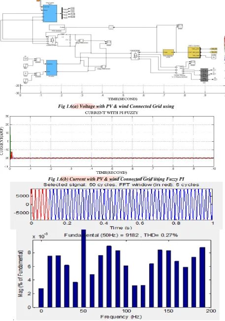
II.RESULT AND CONCLUSIONPV Wind Energy:-
Fig 1.6(a) Voltage with PV & wind Connected Grid using
Fig 1.6(b) Current with PV & wind Connected Grid using Fuzzy PI
.
IJEDR1504179
International Journal of Engineering Development and Research (www.ijedr.org)1042
Three-phase grid-connected rectifier/inverters are used widely in renewable, micro grid and electric po system-connected converters and evaluates the restrictions related through conventional vector control systems and thus, a Fuzzy –based PI vector control scheme This story analyses the restrictions associated with conventional vector control systems for the grid connected converters. These include adding integrals of error signals to the network inputs and introducing a grid disturbance voltage to the outputs of a well-trained network rather than to the inputs of the network. We have demonstrated that these systems are effective. In equally power converter nested loop control and switching environments conditions, the fuzzy-PI vector controller demonstrates strong capability in tracking reference command while holding a high power quality. Under a fault in the grid system, the fuzzy controller exhibits a physically powerful short-circuit ride-through potential. Current and voltage with harmonics at DC connected side using PI value in case of THD values are .27% and 2.16%.when a PV wind PI and PV wind PI Fuzzy are results implemented in the Matlab software. In the PV wind Fuzzy PI controller result are more effective and good as compare to PV wind PI.III.CONCLUSION
In this thesis, we have measured system of wind energy and photovoltaic linked to grid controlled through VSC. For reducing the harmonics in current and potential difference, VSC is connected with PI and PI-Fuzzy.
IV.FURTHER SCOPE OF WORK
Further, ANFIS can be used for more rectification.
Nowadays, the hybrid wind-solar generation system connected in grid is used for the burning research fields. The challenge to implement the project and the new research area of study were the motivations of the project.
V.ACKNOLWDEMENT
The authors would like to thank the reviewers for their helpful comments which contributed to an improve the paper. VI.REFERENCES
[1] Artificial Neural Networks for Control of a Grid-Connected Rectifier/Inverter Under Disturbance, Dynamic and Power Converter Switching Conditions Shuhui Li, Senior Member, IEEE, Michael Fairbank, Student Member, IEEE, Cameron Johnson, Donald C. Wunsch, Fellow, IEEE, Eduardo Alonso, and Julio L. Proaño IEEE TRANSACTIONS ON NEURAL NETWORKS AND LEARNING SYSTEMS, VOL. 25, NO. 4, APRIL 2014.
[2] Vector Control of a Grid-Connected Rectifier/Inverter Using an ArtificialNeural Network Shuhui Li Department of Electrical & Computer Engineering The University of Alabama Tuscaloosa, AL 35487, USA email: [email protected] WCCI 2012 IEEE World Congress on Computational Intelligence June, 10-15, 2012 - Brisbane, Australia.
[3]N.Pandiarajan, RanganathMuthu, “Mathematical Modeling of Photovoltaic Module withSimulink”, First International Conference on Electrical energy system(ICEES),3-5january 2011,pp.258-263.
[4] Soul-KI, Kim, Eung-Sang Kim, Jong-Bo Ahn“Modeling and control of a Grid Connected Wind/PV Hybrid Generation System”.
[5] Ling Lu, Ping Liu,“Research and Simulation on Photovoltaic Power System Maximum Power Control” nternational conference on Electrical and control Engg (ICECE),16-18 sept.2011,pp.1394-1398.
[6] D.Sera,R.Teodorescu,andP.Rodriguez, “PV panel model based on datasheet values” ,IEEE International Symposium on Industrial Electronics,ISIE,PP.2392-2396,2007.
[7] Munish Kumar, “Simulation and Analysis of Grid Connected Photovoltaic System with MPPT” , 2012 IEEE 5th Power India Conference,19-22 dec.2012,pp.1-6.
[8] Andreas Poullikkas, “Implementation of distributed generation technologies in isolatedPower systems,” Renewable and Sustainable Energy Reviews, Volume 11, Issue 1, Pages30-56, January 2007.
[9] N Mohan, TM Underland, WP Robbins. “Power electronics: converters, applications, and design. 3rd ed. John Wiley & sons: 2003.
[10] RW Erickson. “Fundamental of Power Electronics. Norwell, M :Kluwer; 1 ”.
[11] Jinhaeng Jang, Seokjae Choi, Byungcho Choi and Sungsoo Hong, "Average current mode control to improve current distributions in multi-module resonant dc-to-dc converters," Power Electronics and ECCE Asia (ICPE & ECCE), 2011 IEEE 8thInternational Conference, vol., no., pp.2312-2319, May 30 2011-June 3 2011.
[12] Jaime Castelló Moreno, José M. Espí Huerta, Rafael García Gil and Sergio Alejandro González, “ Robust Predictive Current Control for Three-Phase Grid-ConnectedInverters”. IEEE Transactions on Industrial Electronics, vol. 56, no. 6, June 2009. [13] Juan C. Vasquez, Josep M. Guerrero, Alvaro Luna, Pedro Rodríguez and RemusTeodorescu, “ daptive Droop Control pplied to Voltage-Source Inverters Operating inGrid-Connected and Islanded Modes”. IEEE Transactions on Industrial Electronics, vol.56, no. 10, October2009.
[14] Shuhui Li, Timothy A. Haskew, Yang-Ki Hong and Ling Xu, “Direct-current vectorcontrol of three-phase grid-connected rectifier–inverter,” Electric Power SystemsResearch, Volume 81, Issue 2, Pages 357-366, February 2011.